LESSON 3 DC GENERATORS PART I 1 LEARNING


 turn put in magnetic field of two magnetic")

. Rectified e. m. f using the commutator in a DC")


 The geometrical neutral axis (G. N. A. )")

. G. N. A axis")

. Interpoles and compensating windings")


. Compensating windings")


- Slides: 22
LESSON 3: DC GENERATORS PART I 1
LEARNING OBJECTIVES After this presentation you will be able to: Understanding theory of operation for the DC generators. Ø Understanding the role of commutator. Ø Derive the mathematical relationships that describe the dynamics of the DC generator. Ø Understanding the armature reaction phenomenon. Ø 2
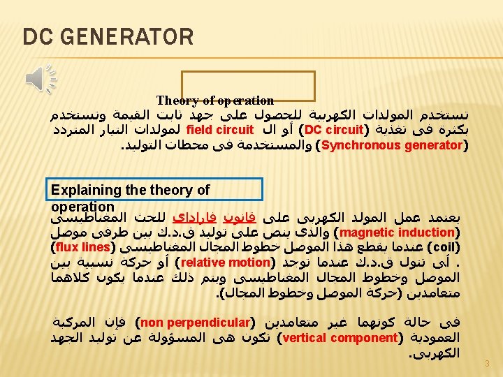
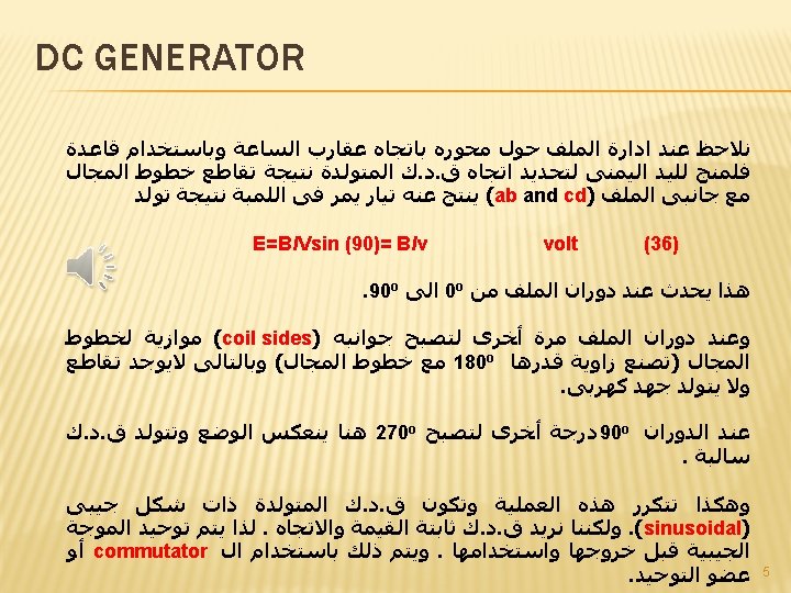
DC GENERATOR Let we have (abcd) turn put in magnetic field of two magnetic poles , suppose that the field from the poles is uniformly distributed and each end of the conductor connected to a slip ring which in terminals connected to an external loads (such as lamps or Analogue Ammeters) as shown in Fig. 40. Fig (40). Stages of generation e. m. f in DC generator 4
DC GENERATOR Commutator ﻋ ﻀﻮ ﺍﻟﺘﻮﺣﻴﺪ A commutator in a DC Machine has alternate bands of Copper and mica. Now when the armature starts to rotate by an external force (in DC Generator), the coils situated in the armature also rotate. The coils are shorted via brush segment with alternate change in influence of poles. This alternate change via the commutator produces unidirectional current flow. Thus, commutation is the positioning of the DC generator brushes so that the commutator segments change brushes at the same time the armature current changes direction. What a commutator does is change the conductor after a half cycle so a single terminal always experiences same EMF. 6
DC GENERATOR Fig (41). Rectified e. m. f using the commutator in a DC machine 7
DC GENERATOR Equation of generated E. M. F 8
Why we use Field winding and Armature winding In a d. c. generator, the purpose of field winding is to produce magnetic field (called main flux) whereas the purpose of armature winding is to carry armature current. Although the armature winding is not provided for the purpose of producing a magnetic field, despite of that the current in the armature winding will also produce magnetic flux (called armature flux). The armature flux distorts and weakens the main flux posing problems for the properation of the d. c. generator. The action of armature flux on the main flux is called armature reaction
Armature reaction If a load is connected to the terminals of the dc machine, a current will flow in its armature windings. This current flow will produce a magnetic field of its own, which will distort the original magnetic field from the machine’s field poles. This distortion of the magnetic flux in a machine as the load is increased is called the armature reaction.
Geometrical and Magnetic Neutral Axes (i) The geometrical neutral axis (G. N. A. ) is the axis that bisects the angle between the centre line of adjacent pole. Fig (42). G. N. A axis (ii) The magnetic neutral axis (M. N. A. ) is the axis drawn perpendicular to the mean direction of the flux passing through the centre of the armature. Clearly, no e. m. f. is produced in the armature conductors along this axis because then they cut no flux. With no current in the armature conductors, the M. N. A. coincides with G, N. A. Fig (43). Alignment of M. N. A with G. N. A axis (ii). In order to achieve sparkles commutation, the brushes must lie along M. N. A.
Explanation The phenomenon of armature reaction in a d. c. generator is shown in Fig. (44). Only one pole is shown for clarity. When the generator is on no-load, a small current flowing in the armature does not appreciably affect the main flux φ1 coming from the pole. When the generator is loaded, the current flowing through armature conductors sets up flux φ2. Fig (ii) shows flux due to armature current alone. By superimposing φ1 and φ2 , we obtain the resulting flux φ3 as shown in Fig. (44) (iii). Referring to Fig (44) (iii), it is clear that flux density at; the trailing pole tip (point B) is increased while at the leading pole tip (point A) it is decreased. This unequal field distribution produces the following two effects: (i) The main flux is distorted.
Fig (44). G. N. A axis
Armature reaction effects the normal operation of DC Generator in many ways. It actually decreases the main flux by 10% which results the generated emf to fall with the increase in load current. Thus as the load increases the armature reaction losses increases and hence the efficiency of the Generator decreases. Three approaches have been developed to partially or completely correct the problems of armature reaction: 1. Brush shifting 2. Compensating windings 3. Commutating poles or inter-poles
Fig (45). Interpoles and compensating windings
BRUSH SHIFTING � Historically, the first attempts to improve the process of commutation in real dc machines started with attempts to stop the sparking at the brushes caused by the neutral -plane shifts. � there are several serious problems associated with it. 1. 2. � the neutral plane moves with every change in load. the shift direction reverses when the machine goes from motor operation to generator operation. therefore, someone had to adjust the brushes every time the load on the machine changed. ,
ANOTHER APPROACH � Sometimes the brushes are fixed in a compromise position (say, one that caused no sparking at two-thirds of full load). � In this case, the motor sparked at no load and somewhat at full load. � If it spent most of its life operating at about two-thirds of full load, then sparking was minimized. APPLICATION OF BRUSH SHIFTING: � � � By about 19 10, the brush-shifting approach to controlling sparking was already obsolete. Today, brush shifting is only used in very small machines that always run as motors. This is done because better solutions to the problem are simply not
Compensating Windings The distorting-magnetizing effect of armature reaction may cause trouble in d. c. machines subjected to large fluctuations in load. In order to neutralize the cross magnetizing effect of armature reaction, a compensating winding is used. A compensating winding is an auxiliary winding embedded in slots in the pole faces as shown in Fig 46. Fig (46). Compensating windings It is connected in series with armature in a manner so that the direction of current through the compensating conductors in any one pole face will be opposite to the direction of the current through the adjacent armature conductor.
Fig (47). Compensating windings
Let us now calculate the number of compensating conductors/ pole face. In calculating the conductors per pole face required for the compensating winding, it should be remembered that the current in the compensating conductors is the armature current Ia whereas the current in armature conductors is Ia/A where A is the number of parallel paths.
Commutating poles or inter-poles The distortion of main field can be prevented by cancelling the effects of the flux produced by the armature current. This can be achieved by installing commutating poles in between two consecutive main poles. The commutating poles are connected in series with the armature winding, but in such a design that they cancel the effect of armature conductor flux and hence we have left only the main field flux.
For large machines, the commutation poles don’t completely neutralize the armature current flux because these high speed machines accept changes in their operation in matter of seconds. Thus in this case compensation windings are installed in slots of the poles faces of main field poles.