LESSON 1 IDENTIFY LABORATORY REFERENCES REVIEW DA FORM

LESSON 1 IDENTIFY LABORATORY REFERENCES, REVIEW DA FORM 1804 AND DA FORM 2077, AND PETROLEUM LABORATORY SIMULATED EXERCISE (SIMPLEX) PROCEDURES

PART A – PETROLEUM LABORATORY REFERENCES Specifications. A specification is a clear, concise, and accurate description of technical requirements. They govern the quality requirements of products used by the military. Specifications are used to purchase petroleum products from the manufacturer and to monitor the product after it has been purchased. Specific ASTM or Federal Test Method Standard (FTMS) test methods are found in Section II and Section IV of the specification �� The military services are responsible for determining the characteristics of a petroleum product. These characteristics are then submitted to an appointed committee that is responsible for developing the specification. The committee normally consists of members from: �� Engine or equipment developers. �� A petrol-chemical company. �� Research and development (R&D) department of the service branch requesting the product.

The first step in developing a specification comes from a company refining the product which it feels meets the requirements for the new piece of equipment. After the sample is developed, it must be isolated and a representative amount sent to the R&D laboratory for processing. Once the product has been tested and all the results are accumulated, the actual writing of the specification is accomplished. It must include the requirements necessary to ensure that the product will perform as intended. It will contain those tests that can be performed under normal field conditions. Once this is completed, the proposed specification is submitted for approval to the Technical Section of the Defense Fuel Supply Center (DFSC) or Defense Logistics Agency (DLA), who is responsible for the standardization of military petroleum specifications. After the specification is approved, it is assigned an alphabetical or numerical designation and is placed on the "Reference List of Specifications and Standards. "

Types of Specifications. �� MIL - A military specification developed and used by military branches of the Department of Defense. �� VV - A federal specification developed by an agency of the government and used by at least two federal agencies, one of which is civilian. It is also used by the Department of Defense. �� JAN - A joint Army and Navy specification. Used only by the Army and Navy.

Numbering System. The numbering system used to identify specifications is in three parts. The first being the types MIL, VV, JAN. The second part consists of a single letter from the first word of the nomenclature of the product as listed in the title of the specification such as: �� F (Fluid or Fuel). �� G (Gasoline or Grease). �� L (Lubricant). �� T (Turbine fuel). �� K (Kerosene). The third part consists of a number of two or more digits assigned upon development. In some cases, the number is followed by a letter indicating revisions, such as: �� MIL-T-5624 (first writing). �� MIL-T-5624 A (first revision). �� MIL-T-5624 B (second revision

Specification Format. The format generally consists of six main sections. Some specifications may have more sections, but the following main sections are always listed. �� Section I. Scope states the type of product. �� Section II. Reference material and applicable documents. �� Section III. Chemical and physical properties. Interpretation of the requirements must be 100 percent accurate. No deviations are allowed. If a requirement is for a minimum degree, or percent, that means the result must be at least what is listed; maximum limits must not be exceeded. �� Section IV. Quality assurance provisions. This area covers sampling, inspections, and other special test procedures. �� Section V. Preparation for delivery. This area covers marking and packaging for shipment. 1 -3 QM 5184 �� Section VI. Notes. This area covers the intended use, how to order, who the custodian of the product is, and other pertinent and miscellaneous information.

Use of ASTM/FTMS. ASTM Standards 05. 01, 05. 02, 05. 03, and 05. 04. The ASTM contains the majority of test procedures used by petroleum laboratory technicians. It is published annually in March. The ASTM may be purchased from the American Society for Testing Materials. Federal test methods (FTMs) cover those methods adopted for use by federal agencies. Usually, only the federal test methods without adopted ASTM test standards are included in the publication. �� These publications tell you what test must be performed and what test method is to be used (for example, American Society for Testing and Materials (ASTM)(FTMS). �� The ASTM/FTMS gives exact procedures to be used when performing testing on all petroleum products and lists specified equipment and materials needed to perform the test.

Use of MIL-HDBK-200. This handbook provides general instructions and procedures to be used worldwide by the military services in quality surveillance of government-owned fuels, lubricants, and related products. Frequently used special test procedures are found in the appendices. In the event laboratory test results have been evaluated, and the product did not meet specification requirements, it is quite possible that the product may still be used according to MIL-HDBK-200 (Quality Surveillance Guidebooks for Fuels, Lubricants, and Related Products) chapter three deterioration/use limits.

Evaluating a Laboratory Analysis Report. Use the following references: �� The applicable specifications and amendments. �� ASTM/FTMS �� MIL-HDBK-200.

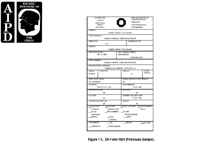
PART B - REVIEW DA FORM 1804 AND DA FORM 2077 FOR COMPLETENESS AND ACCURACY When a sample is turned into the petroleum laboratory for analysis, the senior petroleum laboratory technician transfers the information from the DA Form 1804 (Figure 1 -1) to the heading of the DA Form 2077 (Figure 1 -2). �� Product Nomenclature. �� Specification No. �� Sample Submitted By. �� Amount Product Sample Represents. �� Manufacturer or Supplier of Product. �� Source of Sample. �� Sample Taken By. �� National stock number (NSN). �� Date Sample Taken

Once this information has been transferred to the DA Form 2077, the senior technician then enters the following information: �� Sample No. �� Lab Report No. �� Type of Test(s) to Be Performed According to Specification Requirements. �� Date Sample Received. �� Date Test Started. �� Date Test Completed.
, the laboratory technician forwards the results to the")
Upon completion of the specified test(s), the laboratory technician forwards the results to the senior laboratory technician for review. The senior laboratory technician reviews the results for accuracy and enters the results and a recommendation for disposition on the DA Form 2077 “work copy” and forwards it to the laboratory NCOIC for review approval. Once the petroleum laboratory NCOIC has approved the results and disposition recommendation, a typed DA Form 2077 is prepared from the approved work copy. The original is kept in a permanent file and enough copies to satisfy all interested parties are forwarded to the requesting agency.

The proper completion of DA Form 2077 cannot be stressed enough; as you know, there are many factors involved with the recommended disposition of petroleum products. Some of these factors are as follows: �� Large amounts of product. �� Mission-essential requirements. �� Safety. �� Environmental concerns. As a senior laboratory NCO you must make every effort to ensure that DA Form 2077 is completed as we have discussed and reviewed for accuracy at the required intervals

 PROCEDURES Recommendations. The recommendation for use")
PART C - SIMULATED PETROLEUM LABORATORY EXERCISE (SIMPLEX) PROCEDURES Recommendations. The recommendation for use of a petroleum product is the prime responsibility of the noncommissioned officer in charge (NCOIC) of a laboratory. The use of a petroleum product is based on the results of tests performed by technicians assigned to the laboratory. Therefore, it is important to ensure the correct test method is utilized and all test procedures are strictly followed. Evaluation of a new technician’s laboratory techniques and knowledge of appropriate procedures is essential during the first 90 days on the job, as well as periodically thereafter. During the initial 90 -day period, correct techniques can be implemented and deficiencies eliminated. In addition, periodic checking thereafter will serve as reinforcement.

Testing Errors. It is impossible to list all the errors that may occur when performing various tests since test methods differ greatly. However, the following list contains the general areas you should watch: Procedures. �� Is the correct ASTM or FTM standard being used as outlined in the specification? �� Are all safety procedures being observed? �� Is the correct sequence being followed? Glassware. �� Is the glassware correct for the test method? �� Is it clean and serviceable? Sample preparation. �� Was the sample can shaken? �� Was the correct amount used? �� Was the sample prepared according to the test method? - Was the sample cooled to a specific temperature range? - Was the sample heated to a specific temperature range? - Was the sample filtered? - Was the sample dehydrated?

Chemicals. �� Were the correct chemicals and/or indicators used? �� Was the correct amount used? �� Was the chemical outdated/standardized? �� Was it cloudy? If so, was it filtered or was supernatant used? �� If a substitute was used, is it acceptable according to ASTM procedures? Equipment. �� Bath and oven temperatures must be checked before, during, and upon completion of a test. �� Correctly calibrated thermometers must be used. �� Thermometers must be checked for liquid separation. �� Heating rates and times must be as stated in the text. �� Apparatus must be cooled to room temperature prior to performing another test.
![Other. �� Ensure correct size of flame (flash point, Conradson carbon residue [CCR]). ��](http://slidetodoc.com/presentation_image_h2/3c6332f1794caad5c9178ff5c63ee94f/image-20.jpg "Other. �� Ensure correct size of flame (flash point, Conradson carbon residue [CCR]). ��")
Other. �� Ensure correct size of flame (flash point, Conradson carbon residue [CCR]). �� Ensure correct size of filter (millipore). �� Ensure removal of air bubbles (API gravity, penetration). �� Ensure correct relative centrifugal force (RCF)/revolutions per minute (RPM) (bottom sediment and water [BS&W], precipitation number). �� Ensure correct amount of pressure (gum, foam, oxidation stability). �� Ensure the use of one of the following to determine the correction factor, if needed. - Manometer. - Barometer. - Thermometer. �� Ensure procedure is correctly reported.
. 1 -7 QM 5184 As NCOIC, you must always")
Test Evaluation Process (Procedural Example). 1 -7 QM 5184 As NCOIC, you must always ensure the following steps are taken to perform the test evaluation: �� Given a petroleum sample, complete with sample tag, DA Form 1804 (Petroleum Sample). �� Determine the military specification number. This number is found on the sample tag and on the sample container. �� Determine the product properties. These are found in the military specification. �� Determine the test procedure. Look up the Carbon residue test in the specification. �� Perform the test in conjunction with the applicable ASTM test. You must ensure that all tests are performed in the proper sequence. Observe the test being performed and ensure each step is done "by the book. "

Instruct the Technician in the Correct Procedure When Deficiencies Are Observed. Many times corrective action makes rerunning the test necessary. You must ensure the procedure must be done "by the book" for the result to have meaning. The following actions are taken: �� Look at sample can or tag to find the specification number. If it is not on the tag, call the submitting unit or look in the 9100 Identification List (IL) microfiche for the correct specification number. �� Check the specification to find the test to be run and the correct method. �� Check the appropriate test book (ASTM or FTMS) to find the correct test method to be used. �� Observe the technician to ensure he uses the method correctly. �� Perform corrective action if needed. �� Take the following steps if incorrect test procedures are discovered: - Stop the test. - Identify all errors. - Explain the effect the errors may have on the outcome of the test. - Have the technician review the test procedures. - Have the test rerun by the technician while you observe the procedures.

LESSON 2 CONDUCT A QUALITY SURVEILLANCE PROGRAM

PART A - QUALITY SURVEILLANCE PROGRAM The following responsibilities, at minimum, will be included as part of any quality surveillance program: �� Ensure the quality of product supplied from commercial sources used by the US Army, ARNG, and USAR units. �� Maintain the quality of Army-owned petroleum product and containers. �� Provide support to DLA on a nonreimbursable basis limited to testing and reporting test results on samples submitted by DLA. �� Inspect all bulk petroleum, packaged products, and containers at the frequencies established in MILHDBK 200 or more frequently, if desired, for closer surveillance or when directed by USAPC. �� All packaged products in storage will be inspected every 90 days to determine if product is within shelf life usability and to determine container condition. �� Products identified for shelf life update testing will be reported to USAPC before submitting any samples to designated labs. When products are identified for shelf life update, those products will not be used until laboratory analysis indicates the product meets use limits. USAPC Product Deficiency Investigation (PDI) message, which identify deficient items, will be kept on file for 1 year from date of release. New receipts of products will be screened for items reported in these messages and if received, will be reported to USAPC.

PART B - WORLDWIDE QUALITY SURVEILLANCE PROGRAM As the NCOIC, you must ensure that this program applies to all bulk and packaged petroleum supplied by commercial sources under DLA regional type contracts, procured locally, or received from Army, other military services, or DLA depot stocks. CONUS, USAPC, will establish a CONUS sampling schedule. In addition, USAPC will provide to the submitting activity detailed sampling instructions upon request and advise the submitting activity of the test results and determine if additional quality surveillance samples need be requested for testing.

and determine if additional quality surveillance samples need be requested for testing. �� The commander of the activity required to submit samples under this program will ensure that a petroleum supply specialist is assigned to take product samples and maintain a sample log for all samples submitted indicating assigned sample number, sample history, and test results. A sample taken from the delivery conveyance for the first three separate delivery dates under each new contract, including local purchases, for all types of bulk petroleum product is forwarded to the supporting laboratory. Sample tags will reflect first, second, or third delivery. �� The fuel sample containers will be procured by the submitting activity. Care must be taken to ensure containers are maintained in a usable condition. �� A petroleum sample tag is completed and attached to each sample submitted for laboratory testing. �� Samples of products are forwarded to the laboratory designated within 72 hours after the sample is taken. �� Stocks of motor and aviation fuels at using activities are usually consumed in relatively short periods of time. The unstable character of these products warrants special precautions to prevent damage to equipment. Motor, aviation fuels, and heating fuel will be tested according to MIL-HDBK-200. More information on testing, performance requirements, and instructions of a general nature are given in MILHDBK 114 (Fuels, Mobility, User Handbook). Fuel samples will be forwarded to the supporting laboratory unless otherwise directed. �� All dormant stocks of Army-owned bulk petroleum will be rotated before deterioration occurs beyond acceptable use limits. This guidance and procedures apply worldwide. When test results indicate deterioration trends, stocks will be rotated and consumed while the product is still within specification limits. A report indicating fuel type and problems experienced will be sent to: USAPC ATTN: STRGP-FT, New Cumberland, PA. 17070 -5008.

Overseas commands will establish a sampling schedule at the frequencies established in MILHDBK 200 or more frequently, if desired. �� The joint petroleum office is the area coordinator for the quality surveillance program within its command area. 2 -3 QM 5184 �� The military service within each command is responsible for establishing and maintaining a quality surveillance program, as well as for maintaining and operating laboratories required to perform their tests. �� AR 700 -36 (Overseas Laboratory for Support of Quality Surveillance on Petroleum Products) assigns responsibility for test facilities and for quality surveillance programs for the Army overseas.

Types of Operations. �� Storage operations--for minimum procedures refer to FM 10 -70, FM 10 -67 -1 (Concepts of Petroleum Operations) and Section II, Quality Surveillance. �� Tanker and barge loading & unloading operations refer to FM 10 -70, AR 715 -27 (Petroleum Contract Quality Assurance Manual), Section II, Quality Surveillance. �� Tank car and tank vehicle loading & unloading operations refer to FM 10 -70, AR 715 -27, Section II, Quality Surveillance. �� Pipeline operations--refer to FM 10 -70, AR 715 -27, Section II, Quality Surveillance.

PART C - INSPECTING TANKERS AND BARGES PRIOR TO LOADING This inspection is in addition to the contractor's inspection, who ultimately has the responsibility to inspect all shipping conveyances prior to loading to determine that they are suitable for intended use. A barge is any vessel with less than 30, 000 -barrel capacity. Any vessel with 30, 000 -barrel capacity or more will be treated as a tanker. As the senior petroleum laboratory technician, you must ensure that the inspection is conducted according to the following: Tankers. �� Verify that tanks are prepared for loading. �� Physically enter and inspect each tank to verify suitability to load. A fresh air pack should be on hand for use. �� WARNING: ENSURE THAT EACH TANK HAS BEEN PROPERLY GAS-FREED, TESTED, AND CERTIFIED BY QUALIFIED PERSONNEL. �� Review vessel loading plans to determine their suitability. Verify that all bulkheads are secure and the vessel has double valve separation or line blanks. �� Request a sample of rust, when considered necessary (and under safe conditions) be taken from selected cargo tanks and tested with the product to be loaded or a similar solvent to determine the effect upon the corrosiveness and gum characteristics. �� Tankers scheduled for multiple port loading will have all cargo tanks inspected at the first loading point, if practicable, to determine their suitability for the scheduled products.

Barges. �� Inspection procedures for handling tankers will be applied to barges with the exception as stated in AR 715 -27. �� Physical entry is not required

Inspecting Loading Procedures for Tankers. Preloading Inspection Procedures for Tanker. �� Verify that sampling, testing, and approval of shore tank is completed prior to loading the vessel. �� Check loading lines to determine if they are properly isolated and contain no product detrimental to the cargo. �� Verify that loading lines are full. Obtain opening and closing shore tank gauges (or meter readings where necessary). �� Determine the position of the swing line in the shore tank (where applicable) and setting to prevent loading any free water or sludge from the tank bottom. �� Verify that sea suction and overboard discharge valves are closed and sealed. In the case of split cargo, those values essential to cargo isolation should be sealed with serially numbered seals and their numbers recorded on shipping documents. �� Check cargo first-in and line samples analysis to verify quality of product moving to the vessel. �� Verify that sampling and testing of vessel's cargo tanks during and after loading are done. Loading Inspection Procedure. �� Verify that the fill, approximately 2, 000 to 5, 000 barrels, is pumped into one cargo tank in the vessel. �� Request the ship's officer to switch from this tank to the other tanks and continue loading.

�� If at any time during loading there is an indication of contamination, the loading shall be stopped until the cause and extent of the contamination has been determined. �� Verify that a sample is drawn from the first tank, after a 30 minute wait, and the tests are performed to determine if the quality of the product being loading is satisfactory. �� Verify that when aviation turbine fuel or kerosene is being loaded, loading and inspection procedures of COMSCINST 3121. 3 (series) of 4 March 1977 and COMSCINST 3121. 3 (series) Change 1 of January 1978, subject: Safe Handling of Jet Fuels and Kerosene, are followed: - Prior to loading, all water will be removed from the vessel pipeline and cargo tank. - Verify that the initial loading rate does exceed 3 feet per second (1, 500 barrels per hour through a 12 inch line) through loading lines into the cargo tanks, until the discharge outlet has been covered by at least 3 feet of the product. Thereafter, the normal loading rate may be resumed. - Verify that the loading rate of 3 feet per second is applied to the flow of each tank. - Verify that ullages, water soundings, temperatures, and samples, including the first-in sample, are not taken of any cargo tank until at least 30 minutes after flow into the tank has ceased. In the meantime, loading of other tanks may proceed.

Inspecting Loading Procedures for Barges. Preloading Inspection Procedures. The QSR will ensure the following actions have been taken prior to approving loading: �� Vessel conditioning. �� Vessel tank inspections. �� Vessel tank/internal rust test. �� Vessel loading plans. �� Multiport inspection. �� Quality and quantity determination. Loading Inspection Procedure for Barges. �� Verify that a sample is drawn from the tank, after a 30 minute wait, and tests are performed to determine if the quality of the product being loaded is satisfactory. �� Verify that samples and tests of the contents of the vessel's cargo tanks during and after loading are performed to determine product quality.

Monitoring Postloading Procedures for Tankers and Barges. �� Witness sampling of vessel cargo tanks. �� Monitor cargo tank gaging, temperature determination, and as time will permit, water cuts. �� If possible, water will be stripped ashore before the tanker is released. �� Determine the quantity of fuel loaded. Quantity of product loaded or shipped will be determined by shore tank gages. - Witness shore tank gaging (opening and closing). - Determine shore and vessel net quantities and ship/shore losses or gains. Tanker and barge quantities will be based upon shore tank gages. Report and investigate any quantity discrepancy in excess of 0. 5 percent prior to release of the vessel. �� Verify that contractor maintains the retained sample for the period designated.

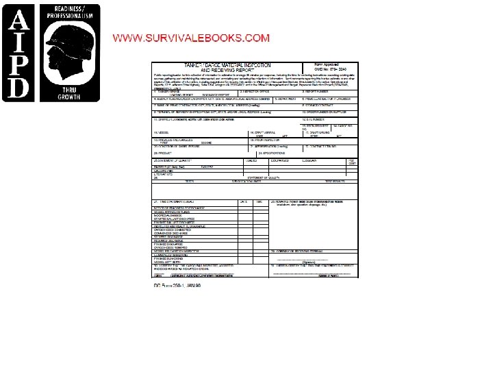
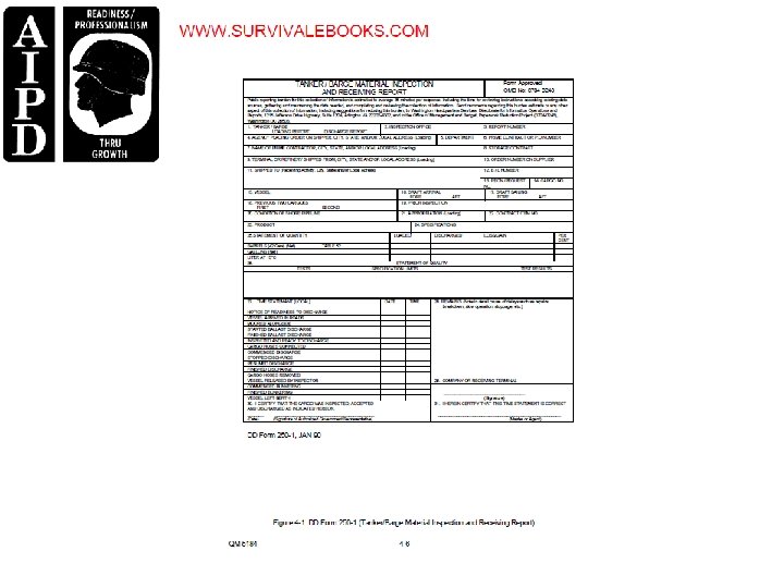
Inspecting Documents Covering Tanker and Barge Loading. �� Verify that DD Form 250 -1 (Tanker/Barge Material Inspection and Receiving Report) (Figure 2 -1), continuation sheet, and ullage or innage report are completed. - If product is loaded from more than one tank, list the test applicable to each tank in separate columns headed by the tank number. - The date the product in each was approved and quantity loaded from each tank will be indicated in the appropriate column. �� Verify that the distribution of documents is made IAW DFARS, Appendix F, Part 7.

Inspecting Discharge Procedures for Tankers and Barges. �� Verify numbers on seals used for split cargo isolations, sea suction valves, and discharge valves before and after discharge. 2 -5 QM 5184 �� Verify that all-levels of samples are taken from each cargo tank. - Perform a visual check on each sample. - In the case of split cargo, different products in adjacent compartments will be tested as necessary to determine if commingling has occurred. - Verify that samples are composited and required retain samples are maintained IAW AR 715 -27. �� Give approval for discharge to proceed if the preliminary examination indicates that the cargo is in order. If the examination indicates that the cargo is not suitable, contact the administrative quality assurance officer for further instructions. �� Verify that gages, and temperature and water soundings have been taken and recorded. These figures will be used to compare with those obtained at the loading point for indications of quality and quantity deficiencies.

�� Maintain close surveillance on products being moved from the vessel to shore tanks. - Check the discharge line. - Witness opening and closing of shore tank gages. �� Verify that quantities received are based on shore tank gages. �� Examine each barge cargo tank to determine if any government-owned product is ROB (Reserve on Board). - If no significant quantity of product remains, sign and retain a copy of the dry tank certification. - Cargo tanks containing appreciable amounts of product will be gaged and the amount present determined, if possible. - Estimates will be made, if it is impossible to obtain accurate figures. - An appreciable amount of product would normally be any quantity estimated at over 15 barrels on a tanker and 5 barrels on a barge. - Verify that all attempts have been made to strip the cargo tanks of product. - Enter the quantities estimated as ROB, the cargo tank number, reason for incomplete discharge and other pertinent information on the discharge report, DD Form 250 -1. For barge discharges, a notation of whether barge or shore pumps were used to discharge the cargo will be annotated

�� Record shipping and handling losses/gains over 0. 5 percent, at discharge destination, on DD Form 250 -1 and indicate the cause for the loss/gain to fullest extent possible. �� Verify that required inspection documents are available. - Completed DD Form 250 -1. - Ullage or innage report. - Other documents that may be required IAW DOD 4140. 25 M (DOD Management of Bulk Petroleum Products, Natuaral Gas and Coal Volumes I-IV). . �� Distribute inspection documents IAW DESC directives or local instructions.

PART D - INSPECTING TANK CARS AND TANK TRUCKS PRIOR TO LOADING Preloading Inspection Procedures. Ensure that personnel perform the following: �� Inspect tank car or truck for cleanliness. The interior, including domes, must be free from loose rust, scales, or dirt, and must be dry (water-free). �� Inspect tank car or truck suitability to receive product. Make sure the product last carried is the same as the product to be loaded. If the product is different, the tank car or truck should be processed IAW Table V, MIL-HDBK-200. �� Look for any foreign objects such as tools, bolts, or old seals that may have fallen into the tank. Objects should only be removed by authorized persons, �� Verify that outlet and safety valves are properly sealed and in operable condition. �� Verify that dome covers and bottom outlet valves are opened and bottom outlet caps on tank cars are removed to allow residue from previous cargoes to drain. Do not allow residue to drain on the ground. Use an approved container. �� Inspect outlet valves. If found to be defective, ensure they are replaced or repaired prior to loading.

Monitoring the Loading of Tank Cars and Tank Trucks. Ensure that personnel perform the following: �� Verify that all outlet valves and caps are replaced prior to filling. �� Verify that all safety precautions are adhered to and observed during loading. �� Verify that preventative measures are taken at top-loading facilities to prevent free falling or splashing during loading operations. - Verify that discharge hoses and loading arm fill pipes are inserted so that they reach the bottom of the tank. - Verify that the fill rate is slow until the hose or fill pipe is covered by at least 6 inches of product. �� Verify that domes and/or unloading valves in the case of tank cars, and all openings in the case of tank trucks, are secured and sealed with serially numbered seals immediately after filling.

Inspecting Loaded Tank Cars and Tank Trucks. Ensure that personnel perform the following: �� Verify that each tank car and tank truck is sampled and tested IAW MIL-HDBK-200, Table III, upon completion of loading to verify product quality. �� Verify that all products that can be visually examined are checked for water and sediment. �� Verify that the contractor maintains a record of test results. �� Verify quantity of products loaded. - Quantities shipped by tank car will be determined IAW contract provisions. - Quantities shipped by tank truck will be determined from the truck calibration table, the net weight of product loaded, or by use of a properly calibrated meter. �� Verify that contractor maintains the retained samples for the period designated in AR 715 -27, Section 6. Inspecting Documents. �� Verify that the corrected API gravity, provided by the contractor, is annotated on the loading documents. �� Inspect prepared documentation for accuracy and completeness.

PART E - PERFORM QUALITY SURVEILLANCE ON PIPELINE MOVEMENTS These procedures apply to movement of product belonging to or to be accepted by the government, except movement of contractor-owned product where quality is verified after receipt at a terminal and prior to delivery to the government. �� Witness the sampling and full specification into the FOB origin and destination contracts to assure the product tendered conforms to the applicable requirements. �� Verify that only heart cuts are transferred into the FOB acceptance tanks, unless specific exception is authorized, for FOB destination deliveries

- Witness sampling and testing of the receipt tanks prior to issue. - Verify that sampling and testing is performed IAW AR 715 -27, Table VI. �� Verify that the cutting of batches into pipeline receiving tanks is IAW the provisions of tariffs and operating agreements. �� Maintain surveillance over the pipeline operations during the transfer to another carrier and at key points in the system during movement. Examine records of pumping rates, progress of tenders, extent of transmit, gravity, and color determination. �� Witness the cutting of tenders or batches into pipeline receiving tanks. �� Verify the quality of product in pipeline receiving tanks after receipt of the tender or batch. - Check calculation of net quantity. - Investigate and report any quantity discrepancy in excess of 0. 3 percent.

�� Maintain familiarity with the procedures used by the carrier to protect or condition the pipeline interior. �� Verify that corrosion inhibitors added to products intended for military use are those approved for the product. �� Evaluate transmixtures, when required. The procedure for this evaluation, including a suitable form for recording data, and a sample of the calculations involved are contained in AR 71527, Tables IV and V. �� Maintain liaison with activities receiving product by pipeline, and render technical assistance as required. �� Verify quantities moved by use of approved meters or from gages at the FOB point.

LESSON 3 SUPERVISE QUALITY SURVEILLANCE TESTING

PART A – QUALITY SURVEILLANCE TESTING Quality surveillance for you as a senior laboratory NCO, will involve having thorough knowledge of all visual and analytical testing methods, as well as the causes and indications of contamination. Fibrous Material. When looking at a clear quart glass container, fibrous material will appear as pieces of thread-like material, similar to fiberglass threads, suspended in the product or lying at the bottom of the container.

Sediment. This will appear as dust, powder, flakes, and/or granular material. Total sediment includes both organic and inorganic material. You may categorize sediment either as coarse or fine. �� Coarse sediment. Sediment which easily settles out of the product or can be removed by filtration. Ordinarily, "coarse sediment" refers to particles of 10 mn (micron) size or larger. This type of sediment is quite visible in a clear glass container. �� Fine sediment. Sediment that is smaller than 10 microns. To a limited degree, this type of sediment can be removed by settling or filtration. Fine particles are not visible to the naked eye as separate or distinct particles. However, the particles will scatter light and may appear as pinpoint flashes of light (like the shimmer of a diamond) or as a slight haze in a sample.

Microbiological Growth. This growth consists of living organisms that grow at the fuel-water interface. These organisms include protozoa, fungus, and bacteria, and they normally have a brown, black, or gray color in addition to a stringy, fibrous-like appearance when observed in a clear glass container. Removal of water bottoms will prevent this problem.

Water in fuels may be either fresh or salty and may be present as either dissolved, entrained, or free water. �� Dissolved water. This is water that has been absorbed by the fuel and is not visible during sample inspections at ambient temperature. When the fuel is cooled, dissolved water becomes entrained and appears as a cloud. Dissolved water is only fresh water and cannot be removed except by freezing. Fuel system icing inhibitor (FSII) is added to jet fuels to prevent dissolved water from freezing. �� Entrained water. This is an emulsion of water in fuel and is visible as a cloud. Entrained water can be removed by filtration. �� Free water. This is water that may appear in the form of a cloud, emulsion droplets, or in larger amounts in the bottom of a tank or other container. Free water is normally readily detectable during visual sample inspections and settles out in storage within 24 hours.

Commingling is the accidental mixing of products that usually occurs when too much interface mixture is pumped into the storage tanks. Upon settling, the contaminants will usually stratify into layers in the tank.
. Scope. This test method")
PART B – TESTING PROCEDURES API Gravity Test (ASTM D-287). Scope. This test method covers the determination by means of a glass hydrometer of the API gravity of crude petroleum and petroleum products normally handled as liquids and having a Reid vapor pressure of 26 psi or less. Summary of Test. The API gravity is read by observing the freely floating API hydrometer and noting the graduation nearest to the apparent intersection of the horizontal plane surface of the liquid with the vertical scale of the hydrometer and observing the temperature of the sample. Significance of Test. Accurate determination of gravity of petroleum and its products is necessary for the conversion of measured volumes to volumes at the standard temperature of 60 degrees Fahrenheit. Also gravity is a factor governing the quality of crude oils. However, the gravity of a petroleum product is an uncertain indication of its quality.

Visual Color. Scope. This test method covers the visual determination of the color of a wide variety of petroleum products such as lubricating oils, heating oils, diesel fuels oils, automotive gasoline and aviation gasoline. Summary of Test. A liquid sample is placed in a clear glass container and the visual color observed. Significance of Test. Visual color of a petroleum product is used for quick identification of a product. A change in product color may indicate contamination or deterioration.
. Scope. This method covers a pass/fail procedure for determining")
Clear and Bright Test (Visual). Scope. This method covers a pass/fail procedure for determining the presence of free water and solid particulate contamination in distillate fuels. Summary of Test. A sample of fuel is swirled in a clean glass jar and examined for visual sediment or water drops below the vortex formed by swirling. A visual inspection for clarity is also performed. Significance. The procedure provides a rapid but nonquantitative method to check for contamination in distillate fuels.
. Scope. This method covers the distillation of motor gasoline, aviation turbine")
Distillation (ASTM D-86). Scope. This method covers the distillation of motor gasoline, aviation turbine fuels, special boiling point spirits, naphtha, white spirit, kerosene, gas oils, distillate fuel oils, and similar petroleum products. Summary of Method. A 100 milliliter (ml) sample is distilled under prescribed conditions which are appropriate to its nature. Systematic observations of thermometer readings and volumes of condensate are made, and from these data, the results of the test are calculated and reported. Significance of Test. Distillation (volatility) characteristics of petroleum products are indicative of performance in their intended applications. Petroleum product specifications generally include distillation limits to assure products of suitable volatility performance. The empirical results obtained by use of this distillation method have been found to correlate with automotive equipment performance factors and with other characteristics of petroleum products related to volatility.

Definitions. �� Initial Boiling Point. The thermometer reading that is observed at the instant that the first drop of condensate falls from the lower end of the condenser tube. �� End Point or Final Boiling Point. The maximum thermometer reading obtained during the test. This usually occurs after the evaporation of all liquid from the bottom of the flask. �� Percent Recovered. The volume in milliliters of condensate observed in the receiving graduate, in connection with a simultaneous thermometer reading. �� Percent Recovery. The maximum percent recovered. �� Percent Loss. 100 minus the total percent recovery. �� Percent Residue. The volume in milliliters of residue. �� Procedure. IAW with American Society for Testing and Materials (ASTM) method D-86, Distillation of Petroleum Products
. Scope. This test method covers a determination of vapor")
Reid Vapor Pressure (ASTM D-323). Scope. This test method covers a determination of vapor pressure of gasoline. It is also applicable to other volatile petroleum products except liquefied petroleum gases and oxygenated fuels. Summary of Method. The gasoline chamber of the vapor pressure apparatus is filled with the chilled sample and connected to the air bath at 100 degrees Fahrenheit. The apparatus is immersed in a bath at 100 degrees Fahrenheit and is shaken periodically until a constant pressure is observed on the gage attached to the apparatus. The gage reading, suitably corrected, is reported as the Reid Vapor Pressure. Significance of Test. RVP is used to predict the vapor locking tendencies of the fuel in a vehicle’s fuel system. Controlled in some areas to limit air pollution by evaporating hydrocarbons while dispensing.
. Scope. These methods cover flash point")
Flash and Fire Point (ASTM D-93, D-92 ). Scope. These methods cover flash point of petroleum products at all ranges. Summary of Method. The test cup is filled to a specified level with the sample. The temperature of the sample is increased rapidly at first and then at a slow constant rate as the flash point is approached. At specified intervals a small test flame is passed across the cup. The lowest temperature at which application of the flame causes the vapors above to ignite, but not burn continuously, is taken as the flash point. Significance of Test. Flash point measures the tendency of the sample to form a flammable mixture with air under controlled laboratory conditions. Flash point is used in shipping and safety regulations to determine QM 5184 3 -4 flammable and combustible materials. Flash point can indicate the possible presence of highly volatile materials in a relatively nonvolatile material. Fire point measures the characteristics of the sample to support combustion. Difference. D-92 (Cleveland open cup) is used to determine flash and fire points of all POL products except fuel oils and products having an open cup flash below 175 degrees Fahrenheit, D-93 (Pensky-Marten) is used mainly to test flash for fuel oils, D-56 (Tag Closed) is used for liquids that flash below 220 degrees Fahrenheit.
. Scope. This test method covers only petroleum oils which are")
Cloud Point (ASTM D-2500). Scope. This test method covers only petroleum oils which are transparent in layers of 38 mm (1 1/2 in) in thickness, and with a cloud point below 49 degrees Celsius (120 degrees Fahrenheit). Summary of Method. The sample is cooled at a specified rate and examined periodically. The temperature at which haziness is first observed at the bottom of the test jar is recorded as the cloud point. Significance of Test. The cloud and pour point of petroleum oil is an index of the lowest temperature of its utility for certain application.
. Scope. This test method is intended for use on any")
Pour Point (ASTM D-97). Scope. This test method is intended for use on any petroleum oil. Summary of Method. After preliminary heating, the sample is cooled at a specified rate and examined at intervals of 3 degrees Celsius for flow. The lowest temperature at which movement of the oil is observed is recorded as the pour point. Significance of Test. The pour point of a petroleum oil is an index of the lowest temperature of its utility for certain applications.
. Scope. This test method covers the determination of the temperature")
Freezing Point (ASTM D-2386). Scope. This test method covers the determination of the temperature below which solid hydrocarbon crystals may form in turbine and reciprocating engine fuels. Summary of Method. A sample of aviation fuel is cooled until crystals of hydrocarbon are formed. The temperature at which these crystals disappear when the fuel temperature is allowed to rise is recorded as the freezing point. Significance of Test. Freezing point of aviation fuels provides guidance as to the lowest temperature of its utility for certain applications.
. Scope. This test method covers the determination of the Kinematic")
Kinematic Viscosity (ASTM D-445). Scope. This test method covers the determination of the Kinematic viscosity of liquid petroleum products, both transparent and opaque, by measuring the time for a volume of liquid to flow under gravity through a calibrated glass capillary viscometer. Summary of Method. The time is measured in seconds for a fixed volume of liquid to flow under gravity through the capillary of a calibrated viscometer under a reproducible driving head and at a closely controlled temperature. Significance. Many petroleum products, as well as nonpetroleum materials, are used as lubricants for such things as bearings, gears, compressor cylinders, and hydraulic equipment. The properation of the equipment depends upon the proper viscosity of the liquid. Thus, the accurate measurement of viscosity is essential to many product specifications
. Scope. This method covers the detection of the corrosiveness to")
Copper Corrosion (ASTM D-130). Scope. This method covers the detection of the corrosiveness to copper of aviation gasoline, aviation turbine fuel, automotive gasoline, natural gasoline, or any other hydrocarbons having a Reid vapor pressure no greater than 18 psi. Summary of Test. A polished copper strip is immersed in a given quantity of sample and heated at a temperature and for a time characteristic of the material being tested. At the end of this period the copper strip is removed, washed, and compared with the ASTM copper strip corrosion standard. Significance. Crude petroleum contains sulfur compounds, most of which are removed during refining. However, of the sulfur compounds remaining in the petroleum product, some can have a corroding action on various metals and this corrosive is not necessarily related directly to the total sulfur content.
. Scope. This test method covers the determination")
Water Reaction of Aviation Fuels (ASTM D-1094). Scope. This test method covers the determination of the presence of water-miscible components in aviation gasoline and turbine fuels, and the effect of these components on the fuel-water interface. 3 -5 QM 5184 Summary. A sample of fuel is shaken, using standardized technique, at room temperature with a phosphate buffer solution. The change in volume of the aqueous layer, the appearance of the interface, and the degree of separation of the two phases are taken as the water reaction of the fuel. Significance. Water extraction of aviation fuels using this technique reveals the presence of relatively large quantities of partially water soluble contaminants such as surfactants. Contamination that affect the interface or create emulsions in the water or fuel layers are apt to disarm filter separators quickly and allow free water and particulates to pass. A change in volume of the aqueous layer indicates that water soluble materials such as alcohol or ethers are present.
. Scope. This test method describes a")
Particulate Contaminant in Aviation Turbine Fuels (ASTM D-2276). Scope. This test method describes a procedure for the evaluation of particulate contaminant in aviation turbine fuels. Summary. A known volume of fuel is filtered through a preweighed test membrane filter and the increase in membrane filter weight determined after washing and drying. The total contaminant is determined from the increase in weight of the test membrane filter relative to the control membrane filter. Significance. This test method provides gravimetric measurements of the particulate matter present in aviation turbine fuels, which must be minimized to avoid filter plugging and other operational problems
. Scope. This test method covers")
Existent Gum in Fuels by Jet Evaporation (ASTM D-381). Scope. This test method covers the determination of the existent gum in motor gasoline and aircraft fuels at the time of the test. Summary. A measured quantity of fuel is evaporated under controlled conditions of temperature and flow of air or steam. For aviation gasoline and aircraft turbine fuel, the resulting residue is weighed and reported as milligrams per 100 ml. for motor gasoline. The residue is weighed before and after extracting with nheptane, and the results are reported as milligrams per 100 ml. Significance. The true significance of this test method for determining gum in motor gasoline is not firmly established
. Scope. This method provides a rapid portable")
Water-Separation Characteristics - MICRO WSIM (ASTM D-3948). Scope. This method provides a rapid portable means for field and laboratory use to rate the ability of aviation turbine fuels to release entrained or emulsified water when passed through fiberglass coalescing material. It is intended to measure the water-separation characteristics of fuel as produced, after it has been blended with additives or delivered to the point of use. Summary. The fuel sample is emulsified with water in a syringe using a high-speed mixer. The emulsion is then expelled from the syringe at a programmed rate through a standard fiberglass coalescer, and the effluent is analyzed for uncoalesced water by light transmission measurement. High ratings indicate the water is easily coalesced and, therefore, that the fuel is relatively free of surfactant materials. Significance. The test provides a measure of the presence of surface active substances in aviation turbine fuels. It can detect carry-over of traces of refinery treating residues in fuel as produced. It can also detect surface active substances added to or picked up by fuel during handling from point of production to point of use.
. Scope. This")
Fuel System Icing Inhibitor in Hydrocarbon Fuels - FSII (FTM 5327. 4). Scope. This method is used for determination of 0. 05 to 0. 20 volume percent ethylene glycol monomethyl ether (EGME) and diethylene glycol monomethyl ether (Di. GME) in hydrocarbon fuels. Summary. Two compounds are approved as fuel system icing inhibitors (FSII) in hydrocarbon fuels. In this method, FSII will denote EGME or Di. GME. The test consists of removing the FSII from the hydrocarbon fuel by extraction with water. The water solution is allowed to react with an excess of standard potassium dichromate solution in the presence of sulfuric acid, and the excess dichromate is determined iodometrically. Significance. FSII is an additive in aviation turbine fuel that prevents dissolved water from freezing at high altitudes (above 8, 500 feet). If the FSII % by volume is too low: DETERIORATION (loss of additive) due to CONTAMINATION with water.

PART C - CARE AND USE OF BALANCES Weighing is a task that is constantly performed by laboratory technicians. Therefore, you must ensure that the technicians know the correct balance to use and how to use it. Erroneous weighing or the improper balance can QM 5184 3 -6 result in false results when performing laboratory tests. As a senior petroleum laboratory NCO, it is your responsibility to ensure that all balances are serviceable and properly calibrated at all times. Significance -- Weighing is a necessary part of running a test to obtain results and making solutions.
 of")
Types of Balances: �� Analytical Balance-- Used for precision weighing (0. 0001 gram) of small quantities. Some features on a single-pan analytical balance include: easy-to-read display, separate sealed keys, and automatic calibration. �� Harvard Trip Balance -- Precision balance used for weighing substances in the petroleum laboratory. It should be used on a reasonably flat and level surface. In this setting a very near balance should be attained with the beam and tare poises all the way to the left. �� Torsion and Triple Beam Balances -- Used when precise weighing is not required. For instance, it would be used when determining the appropriate weight of tubes to be centrifuged. Use of Balances. Use of the Analytical Balance. �� Press the TARE on the balance to zero the display. Place a sheet of quantitative filter paper on the pan of the balance. �� Use a clean, dry spatula to carefully measure the required quantity of solute calculated. �� Read the display weight after the display is stable, indicated by the no-motion symbol switches on or off. �� Record the weight of the solute for reference.

Use of the Harvard Trip Balance. �� Zero the balance. Adjust the knurled zero knob at the right end of the beam, if the scale is not balanced at zero when set upon the working surface. �� Weigh substance. Place the substance to be weighed on the left platform of the balance. Move the poises to a position that will restore the scale to balance. The lower poise is moved to the right until the first notch is reached which causes the right platform of the scale to drop. The lower poise is then moved back one notch, which will cause the right platform to rise again. The upper poise is then moved to the right until the scale is brought into balance. �� Read the results directly from the beams by adding the amount indicated on the lower and upper beams. �� Record the weight of the solute for reference
. �� Level")
Use of the Triple Beam Balance (when precise weighing is not required). �� Level and zero the balance. Select a reasonably flat and level surface on which to use the balance. Adjust the knob at the left end of the beam to obtain zero balance. �� Weigh substance. Place substance to be weighed on the load receiving platform. Move the center poise to the first notch where it causes the beam pointer to drop, then move it back one notch and the pointer will rise. �� Read the results as the weight of the substance by adding the values indicated by the poises.

Care of Balances. �� Balances should be used on reasonably flat and level surfaces. �� When transporting balances, take care that they do not receive any sharp blows or unnecessarily rough treatment. Cleaning of Balances – �� Balances should be kept clean at all times. �� Dirt and moisture should not be allowed to accumulate in the vicinity of these balances. �� Analytical Balance. Refer to manufacturer's manual for specific cleaning procedures. �� Harvard Trip and Triple Beam Balances. Scale bearings should never be lubricated or oiled. Should the bearings become dirty, attempt to clean them by blowing out with dry air blast. Occasionally, the magnet face will need to be dusted. This is best done by inserting a piece of adhesive tape in the magnet slot and pressing it against the magnet face to pick up attracted material and prevent it from interfering with movement of the damper vane

LESSON 4 CONDUCT QUALITY ASSURANCE

PART A- CONTAMINATION Types of Contamination. A contaminated product is one that contains some material not normally present, such as water, solids, or other grades of petroleum products. Such a mixture may modify the quality of the product permanently or add undesirable characteristics. Contamination usually results through carelessness, accident, inability or neglect to follow procedures or through sabotage. Water may be fresh or salt. Saltwater will be present as free water, where freshwater can be present as either free or dissolved water.

�� Examples of water contamination in bulk storage tanks. Conical, flat, and dome roof tanks can become contaminated by rain, snow, moisture in the atmosphere, water bottoms present in the tanks, or line flush. Floating roof tanks are usually contaminated when the roof seal becomes unserviceable and leaks or if the roof drain lines that allow collected water on the roof of the tank to drain off become clogged. Water contamination of pipeline can occur when the line flush is pumped into the line or if water collects in low spots along the line. Tankers can become contaminated if the hatches are left open and rain or waves get into the tank. �� Effects of water contamination. If a product is contaminated with water, sludge will form, the fuel will not burn efficiently, the water in the fuel can freeze or cause rusting in the storage container, and it will support microbiological growth. �� Indications of water contamination. The appearance of lube oils will be milky, and light distillates will appear hazy or cloudy. The water by distillation and the bottom sediment and water tests will show the presence of water, and a product will start foaming at approximately 200 degrees Fahrenheit when being tested for flash or fire points. �� Recommendations for use. The product should be passed through a filter/separator to remove water. It can be dehydrated by heating. In the case of lube oil it is usually sent to the Defense Reutilization and Marketing Office (DRMO).

Solid Contamination. Course sediment is sediment which is larger than 10 microns in size. Fine sediment is sediment which is smaller than 10 microns in size. �� Definition: Any form of sediment may clog filters or injector nozzles of aircraft fuel systems. The abrasive action of this sediment may cause damage to finely tooled fuel system components. Large particles usually indicate a failure somewhere in the fuel system. �� Examples: Rust: A product of corrosion. It is brittle and powders readily. It is insoluble in water. It is usually caused by water present in the system or from empty containers once they are put into service. Rust can usually be removed by passing the fuel through a filter separator. Millscale: Is a magnetic product formed on iron and steel during the manufacturing process. It is blue black in color and is brittle. It is usually found when new tanks or pipes are first placed into service, can be removed by filtering and usually will not settle out of fuel. Bronze: If present in fuel it is usually caused by worn impellers in the fuel pumps. Lint-fibers: Caused by paper type filter cartridges, cloth, and cotton waste. Some fibers cannot be detected without microscopic examination. Can usually be corrected by changing the filter elements. However it is sometimes caused when new filters are placed in service. �� Effects of solids contamination include clogged fuel filters and lines, increased wear of parts caused by abrasion, and increased maintenance. Recommendations for use: Allow fuel to settle, pass product through a filter/separator, and, if solids are removed, use for intended purpose.

Commingling is the accidental mixing of two or more products and can be a serious or minor problem depending on the product that was contaminated, type of contaminating product, or degree of contamination. �� The effects of commingling varies with each product; however, usually there is a change in product color and specification. Critical tests that are normally affected include Reid vapor pressure, flash point, and distillation. �� Indication of commingling can be detected by a color change in the product and the API gravity. Both the visual color and the gravity of the fuel should be checked on a regular basis at the storage location. 4 -3 QM 5184 �� Recommendation for use: After two products have been commingled and the laboratory has tested the fuels, the commingled product is blended with as an on-grade product to either return the properties to the use limits of the original product or to downgrade the product. Most products can usually be recovered assuming there is enough storage space within the tanks for the required blending. Blending should only be done to meet use limits, and the product should be used as soon as possible after it has been certified as meeting use limits by the laboratory.

Deterioration refers to changes occurring in a product while the product lies in storage. Deterioration becomes more marked as the product ages, such as darkening of a product. It may be initiated or hastened by the storage conditions. It is not normally noticed by personnel handling the product, as deterioration of the product may not visibly affect the color or appearance. Discovery of deterioration is dependent upon an adequate quality surveillance program. Most common forms of deterioration are weathering, gum formation, and loss of additives.

Weathering is due to evaporation of the more volatile components, referred to as "lights ends" of a product. It is most noticeable in light products such as gasoline. Rate of evaporation increases markedly with rises in temperature. �� Storage tanks are vented to the air. Increase in evaporation produces pressures which force excessive vapors to escape to the atmosphere through tank vents, thus allowing vapor loss. Lowering of the temperature decreases vaporization, thus lowering tank pressures, and causing fresh outside air to be drawn in to the tank through the vents. This operation is referred to as “breathing. ” Breathing may be partially controlled by pressure-vacuum release valves on the tank. �� Indication of deterioration by weathering: loss of volatile components, low RVP, high IBP. Effects: poor starting of engines in cold weather. Recommendations for use: Blend with on-grade product at a predetermined ratio, and use as soon as possible.

Gum. Gum formation is the most common and troublesome result of deterioration suffered by internal combustion engine fuels. It is caused by the presence of unsaturated hydrocarbons in the presence of oxygen undergoing chemical changes (polymerization of unsaturated hydrocarbons, the process of uniting light olefins to form hydrocarbons of a higher molecular weight). Chemical changes produce a gummy material. �� Gum materials are insoluble, are difficult to vaporize, clog jet and fuel lines, form deposits on valves, cause incomplete combustion, and cause increased maintenance. After gummy material forms, a resinous material forms which settles out on walls and bottoms of containers and is difficult to remove. �� Oxidation inhibitors do not offer permanent protection. Indications of gum formations are darkening of JP 4, haze, or a gray cast in fuel. Oily gum is indication of contamination with heavier product. Dry gum is indication of deterioration. Recommendation for use: Blend with ongrade product and use as soon as possible.
, color, fuel system")
Loss of Additives: Loss of additives such as tetraethyl lead (TEL), color, fuel system icing inhibitor (FSII), or oxidation inhibitor means a loss in the performance of or in the management of the fuel. �� Tetraethyl lead (TEL) loss is caused by long term storage or exposure to light. Effect on performance is reduced power and engine knock. Indications of loss are a haze due to formation of lead and a low octane rating or performance number. Recommendation for use: If precipitate will not settle, pass through a filter/ separator. If it meets engine tests and all other use limits, use as soon as possible. If filtering fails, blend with on-grade product, or downgrade to meet TEL requirements and use as soon as possible. �� Loss of color is caused by long-term storage/exposure to light. Effect: psychological effect on consumer about the quality of the fuel and the management of the fuel during interfaces. Recommendation for use: Use as soon as possible if product meets other test requirements. �� Fuel system icing inhibitor (FSII) loss is caused by extraction by water while the fuel is in storage. This loss effects the freezing point of water in the fuel. Ice can form in the fuel causing fuel line clogging which causes engine flameout or stalling. Loss of additive is indicated by low FSII content and can be corrected by blending with on-grade product or by reinjecting FSII. �� Oxidation inhibitors found in light distillates. The additive is lost usually due to manufacturer's mistakes or incompatibility of additives. Effect of the loss of this additive is gum formations in the fuel which will be indicated by the gum test. Corrected by blending and using as soon as possible.

PART B - RECLAMATION/DISPOSITION PROCEDURES QM 5184 4 -4 Reclamation/disposition procedures include the identification of the problem (product contaminated or deteriorated), the cause of the problem, and the procedure to correct it. �� Downgraded. Assigned for use where a lower grade of product would normally be employed, provided it meets the requirements for the lower grade of product. This operation can result in the serious shortage of a product at a time of great need, may necessitate segregation and careful planning and supervision of the issue, and may cause increased maintenance. �� Blended. Mixing with a larger quantity of the same product of higher quality. This involves equipment and storage facilities not always readily available. This may cause a decrease in the proper storage capacity of a depot, and, therefore the efficiency of the operation will be reduced. �� Recirculating. Cleaning the product by passing it through filter/separators. �� Dehydration. Removing water by a filtering or settling process. �� Inhibiting. Adding or restoring additives that are missing. �� Disposition Procedures: When a DLA-owned product does not meet specification limits at immediate storage points, the activity having physical possession of the product will contact the following activity for a decision on the disposition or use:

The Defense Fuel Supply Center ATTN: DFSC-TB Cameron Station, Alexandria, Virginia 22314 When an Army-owned product does not meet use limits at the location of use, the following activity will be contacted for disposition instructions: US Army General Materiel and Petroleum Activity ATTN: STSGP-FT New Cumberland, Pennsylvania 17070.

The request for disposition instructions should include the following information: �� Specification and grade. �� Quantity. �� Location. �� Date of receipt. �� Name of manufacturer, contract number, batch number, qualification number, date of manufacture. �� Type of container or storage. �� Accountable military department. �� Need for replacement product. �� Detail laboratory test results. �� Recommended alternate use, disposition, or recovery measures. As a last resort turn into the Defense Reutilization and Marketing Office (DRMO).

PART C - TANKER/BARGE OPERATIONS QUALITY ASSURANCE DFSC furnishes advance information on impending lifting of petroleum products in tankers and barges, to include any changes that may occur. The QAR will maintain liaison with the refinery, terminal, MSC, and the vessel’s agent or barging company to determine more definitive ETAs. The QAR will promptly report any delays encountered during tanker/barge operations to DFSC.
. �� The QAR at the first")
Inspection of Tankers With Inert Gas Systems (IGS). �� The QAR at the first loading port shall inspect the entire gas-free IGS tanker for suitability to load. For IGS tankers, this inspection is final. For safety reasons, QARs at subsequent loading ports cannot enter any cargo tanks. �� Cargo tank preparation cleaning requirements in Table II, DLAM 4155. 1 must be met for all loading. �� Tanker will arrive at first loading port gasfree to permit the QAR entry and inspection of all product tanks. �� Prior to discharge, product ullage is to be found using the sonic probe and water is to be checked using the tape and bob. �� After discharge, dry tank inspection must be performed using tape and bob with product paste as visual examination of tanks is not possible

Inspection Procedures for Loading Tankers and Barges. Preloading Inspection. Ensure that the subsequent procedures are followed: �� Assure product quality in shore tanks and all lines used in loading. �� QAR will witness appropriate verification test of product to be loaded. �� Prior to loading, all lines will be dropped and water removed form cargo tanks. �� Check the cargo layout and loading plans. The QAR and the master of the vessel (or representative) must concur on the cargo layout and loading plan. �� Check ship’s log on nature of previous cargoes and leaks. �� Check loading lines to ensure they are properly isolated and do not contain product detrimental to the cargo. �� Witness opening and closing of shore tank gages. The QAR will independently compute the quantity of product loaded on vessels using shore tank gages. �� Close and seal the sea suction and overboard discharge valves prior to loading. �� Ensure vessel is grounded to dock. �� All lines will be full/empty before and after loading/discharge operations. �� Preparation of cargo tanks has been performed in accordance with Table II, DLAM 4155. 1. �� The QAR will ensure that necessary safety precautions have been taken and that each cargo tank has been properly gas-freed, tested, and certified by qualified personnel.

�� The QAR will personally enter and inspect each tank to verify suitability to load. �� When tanks have been partially filled at a previous lifting point and are to be topped-off, the product should be sampled and tested as deemed necessary by the QAR prior to topping off. �� Cargo tanks which have been loaded at a previous port and which are adjacent to the tanks to be loaded should be sampled. The samples should then be held for testing in the event of loading difficulty that indicates possible cargo commingling. �� All product aboard the vessel, including bunker tanks, shall be gaged before and after loading, unless otherwise directed. �� When considered necessary, the QAR will require a rust test IAW paragraph 4. 4. 3, DLAM 4155. 1. �� In the case of split cargoes, the QAR will ensure that: - The vessel is structurally suitable for handling two or more grades of product simultaneously without contamination. - Bulkheads are secured. - If valves are used, such valves will be lashed and sealed in proper position to ensure against misuse. �� Vessel movements will not be expedited at the expense of quality or quantity determinations. �� Any conditions contributing to delays in port which increase loading or discharge time will be recorded on the DD Form 250 -1 (Figure 4 -1).

During-Loading Inspection. �� Initial loading will be at a rate not in excess of three feet per second through loading lines into cargo tanks until the discharge outlet has been covered by three feet of product. Then, normal loading may be resumed. �� At the start of loading, displace a sufficient amount of product through pipeline system into one cargo tank in the vessel. Then, switch to other tanks and continue loading. The first tank will be sampled and tested to assure the quality of product is satisfactory. �� If at any time there is an indication of contamination, the operation will be stopped until the cause and extent has been determined. �� Check and analyze line and dock header samples to verify quality of product moving to the vessel. Samples will be taken under line flow conditions. �� Sampling and testing of vessel cargo during and after loading will be done IAW Table VI, DLAM 4155. 1.

After-Loading Inspection. �� The QAR will personally witness the sampling, gaging, temperature determination, and water cuts on the vessel’s tanks after loading when it is safe (minimum of 30 minutes after loading to the tank has stopped). �� Calculate cargo quantity from vessel calibration tables for comparison with shore tank quantity figures. �� Differences between ship and shore figures which are in excess of 0. 5 percent will be investigated by the QAR prior to release of the vessel and entered on DD Form 250 -1. �� The QAR will provide information to the contractor for completion of DD Form 250 -1. �� The QAR will verify the numbers on all seals before and after discharge. �� Before unloading of the vessel is started, all-levels samples will be taken from each cargo tank and will be examined. �� Gages, temperature, and water soundings on cargo tanks of the vessel will be taken and made a matter for record. Figures will be compared with those obtained at the loading point. �� The QAR will participate in key operations as specified for loading operations as applied to cargo discharging. �� The QAR will examine each cargo tank of the vessel to determine if any product remains therein before issuing a dry tank certificate.
- Slides: 92