LED Infrared 850 nm Description This is a


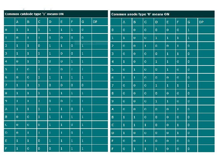
 – In the common cathode display, all the cathode")
 – In the common anode display, all the anode")


- Slides: 12
LED - Infrared 850 nm Description: This is a very simple, clear infrared LED. These devices operate between 840 -850 nm and work well for generic IR systems including remote control and touch-less object sensing. Pair them with any of our IR receivers. 1. 5 VDC forward voltage and 50 m. A max forward current. Documents: https: //www. sparkfun. com/datasheets/Components/LE D/YSL-R 531 FR 2 C-F 1. pdf
LED – Ultraviolet Description: This is a simple 5 mm LED with an interesting array of applications. This UVLED can be used for counterfeit detection (bills, credit cards, documents, etc), sterilization, pesticide, black lights, sun burns, the list goes on. Please wear eye protection when using these LEDs. Features: T 1 ¾ 5 mm clear lens 395 -400 nm 100 -180 mcd 3 -3. 6 V forward drop Documents: https: //www. sparkfun. com/datasheets/Components/ LED/YSL-R 547 P 4 C-E 3. pdf
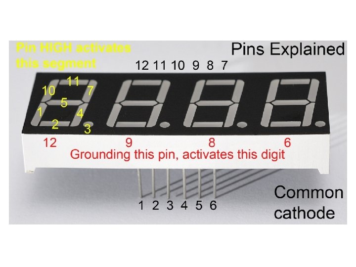
• The 7 -segment display, also written as “seven segment display”, consists of seven LEDs (hence its name) arranged in a rectangular fashion as shown. • Each of the seven LEDs is called a segment because when illuminated the segment forms part of a numerical digit (both Decimal and Hex) to be displayed. • An additional 8 th LED is sometimes used within the same package thus allowing the indication of a decimal point, (DP) when two or more 7 -segment displays are connected together to display numbers greater than ten.
The displays common pin is generally used to identify which type of 7 -segment display it is. As each LED has two connecting pins, one called the “Anode” and the other called the “Cathode”, there are therefore two types of LED 7 segment display called: Common Cathode (CC) and Common Anode (CA). The difference between the two displays, as their name suggests, is that the common cathode has all the cathodes of the 7 -segments connected directly together and the common anode has all the anodes of the 7 -segments connected together and is illuminated as follows. 7 -Segment Display Segments for all Numbers.
1. The Common Cathode (CC) – In the common cathode display, all the cathode connections of the LED segments are joined together to logic “ 0” or ground. The individual segments are illuminated by application of a “HIGH”, or logic “ 1” signal via a current limiting resistor to forward bias the individual Anode terminals (a-g). Common Cathode 7 -segment Display
2. The Common Anode (CA) – In the common anode display, all the anode connections of the LED segments are joined together to logic “ 1”. The individual segments are illuminated by applying a ground, logic “ 0” or “LOW” signal via a suitable current limiting resistor to the Cathode of the particular segment (a-g). Common Anode 7 -segment Display
Although a 7 -segment display can be thought of as a single display, it is still seven individual LEDs within a single package and as such these LEDs need protection from over current. LEDs produce light only when it is forward biased with the amount of light emitted being proportional to the forward current. This means then that an LEDs light intensity increases in an approximately linear manner with an increasing current. So this forward current must be controlled and limited to a safe value by an external resistor to prevent damage to the LED segments. The forward voltage drop across a red LED segment is very low at about 2 -to-2. 2 volts, (blue and white LEDs can be as high as 3. 6 volts) so to illuminate correctly, the LED segments should be connected to a voltage source in excess of this forward voltage value with a series resistance used to limit the forward current to a desirable value. Typically for a standard red colored 7 -segment display, each LED segment can draw about 15 m. A to illuminated correctly, so on a 5 volt digital logic circuit, the value of the current limiting resistor would be about 200Ω (5 v – 2 v)/15 m. A, or 220Ω to the nearest higher preferred value
Driving a 7 -segment Display using a 4511
Each LED segment of the common cathode display has its own anode terminal connected directly to the 4511 driver with its cathodes connected to ground. The current from each output passes through a 1 kΩ resistor that limits it to a safe amount. The binary input to the 4511 is via the four switches.