
Lectures 21 22 FPGA and TopDown Design Flow
- Slides: 24
Lectures 21, 22 FPGA and Top-Down Design Flow Mar. 3 and 5, 2003 Modern VLSI Design 3 e: Chapter 3 1 Partly from 2002 Prentice Hall PTR
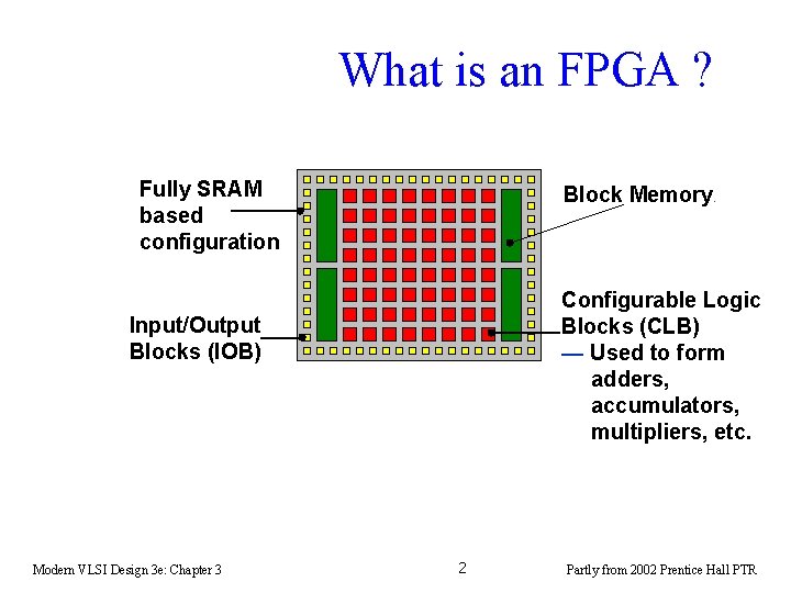
What is an FPGA ? Fully SRAM based configuration Block Memory. Configurable Logic Blocks (CLB) — Used to form adders, accumulators, multipliers, etc. Input/Output Blocks (IOB) Modern VLSI Design 3 e: Chapter 3 2 Partly from 2002 Prentice Hall PTR
What a Range of Devices: Which One? w The lowest cost devices for DSP applications ($5 to $10) — 96 to 864 CLBs with up to 48 k-bits RAM w The father device from which all Virtex devices have been derived — Rarely used for new designs — 384 to 6144 CLBs with up to 128 k-bits RAM Cont’d on next slide Modern VLSI Design 3 e: Chapter 3 3 Partly from 2002 Prentice Hall PTR
What a Range of Devices: Which One? w 384 to 16224 CLBs with up to 832 k-bits RAM w For those particularly memory intensive algorithms — 2400 to 4704 CLBs with up to 1120 k-bits RAM w 128 to 23, 296 CLBs* with up to 3024 k -bits RAM — Latest family and most DSP-focused FPGA architecture ever to be released *scaled to enable comparison Modern VLSI Design 3 e: Chapter 3 4 Partly from 2002 Prentice Hall PTR
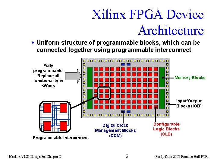
Xilinx FPGA Device Architecture w Uniform structure of programmable blocks, which can be connected together using programmable interconnect Fully programmable. Replace all functionality in <50 ms Memory Blocks Input/Output Blocks (IOB) Programmable Interconnect Modern VLSI Design 3 e: Chapter 3 Digital Clock Management Blocks (DCM) 5 Configurable Logic Blocks (CLB) Partly from 2002 Prentice Hall PTR
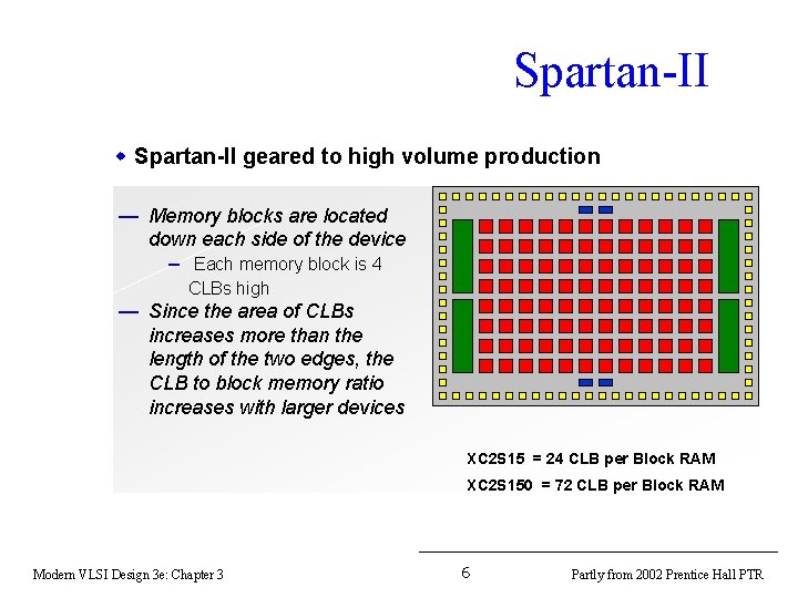
Spartan-II w Spartan-II geared to high volume production — Memory blocks are located down each side of the device – Each memory block is 4 CLBs high — Since the area of CLBs increases more than the length of the two edges, the CLB to block memory ratio increases with larger devices XC 2 S 15 = 24 CLB per Block RAM XC 2 S 150 = 72 CLB per Block RAM Modern VLSI Design 3 e: Chapter 3 6 Partly from 2002 Prentice Hall PTR
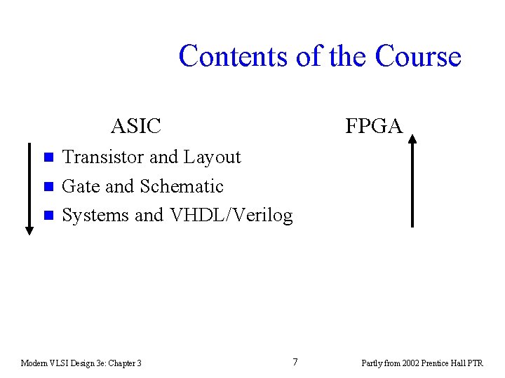
Contents of the Course ASIC n n n FPGA Transistor and Layout Gate and Schematic Systems and VHDL/Verilog Modern VLSI Design 3 e: Chapter 3 7 Partly from 2002 Prentice Hall PTR
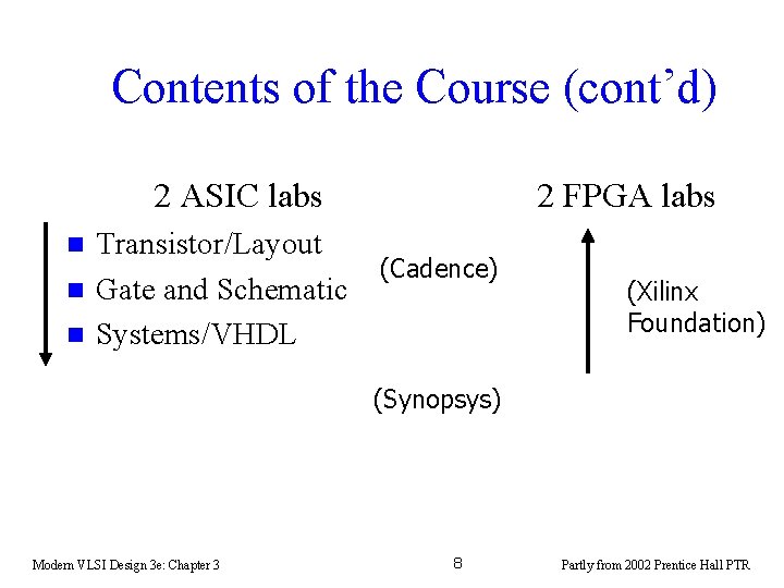
Contents of the Course (cont’d) 2 ASIC labs n n n Transistor/Layout Gate and Schematic Systems/VHDL 2 FPGA labs (Cadence) (Xilinx Foundation) (Synopsys) Modern VLSI Design 3 e: Chapter 3 8 Partly from 2002 Prentice Hall PTR
Xilinx Foundation Tutorial Lab 3: Top-down design Lab 4: Download to FPGA development board Modern VLSI Design 3 e: Chapter 3 9 Partly from 2002 Prentice Hall PTR
Lecture 23 Driving Large Load Pass Logic Mar. 7, 2003 Modern VLSI Design 3 e: Chapter 3 10 Partly from 2002 Prentice Hall PTR
Driving large loads n Sometimes, large loads must be driven: – off-chip; – long wires on-chip. n Sizing up the driver transistors only pushes back the problem—driver now presents larger capacitance to earlier stage. Modern VLSI Design 3 e: Chapter 3 11 Partly from 2002 Prentice Hall PTR
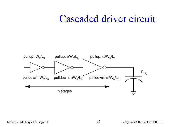
Cascaded driver circuit Modern VLSI Design 3 e: Chapter 3 12 Partly from 2002 Prentice Hall PTR
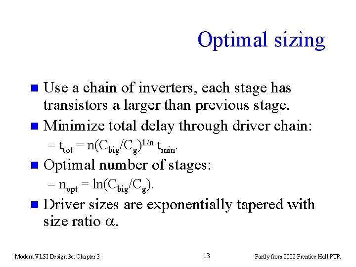
Optimal sizing Use a chain of inverters, each stage has transistors a larger than previous stage. n Minimize total delay through driver chain: n – ttot = n(Cbig/Cg)1/n tmin. n Optimal number of stages: – nopt = ln(Cbig/Cg). n Driver sizes are exponentially tapered with size ratio a. Modern VLSI Design 3 e: Chapter 3 13 Partly from 2002 Prentice Hall PTR
Example 1 Modern VLSI Design 3 e: Chapter 3 14 Partly from 2002 Prentice Hall PTR
Topics n Swtich logic. Modern VLSI Design 3 e: Chapter 3 15 Partly from 2002 Prentice Hall PTR
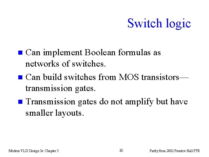
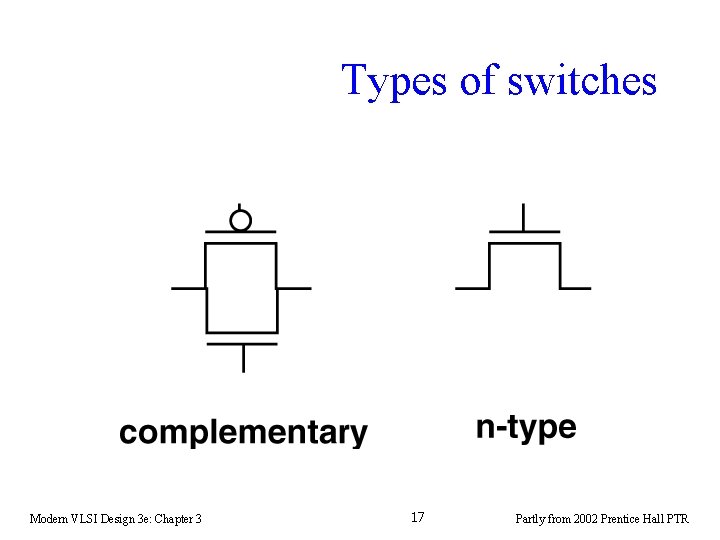
Switch logic Can implement Boolean formulas as networks of switches. n Can build switches from MOS transistors— transmission gates. n Transmission gates do not amplify but have smaller layouts. n Modern VLSI Design 3 e: Chapter 3 16 Partly from 2002 Prentice Hall PTR
Types of switches Modern VLSI Design 3 e: Chapter 3 17 Partly from 2002 Prentice Hall PTR
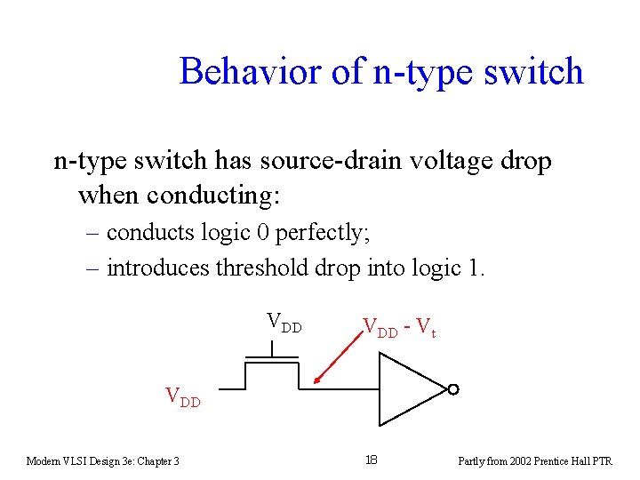
Behavior of n-type switch has source-drain voltage drop when conducting: – conducts logic 0 perfectly; – introduces threshold drop into logic 1. VDD - Vt VDD Modern VLSI Design 3 e: Chapter 3 18 Partly from 2002 Prentice Hall PTR
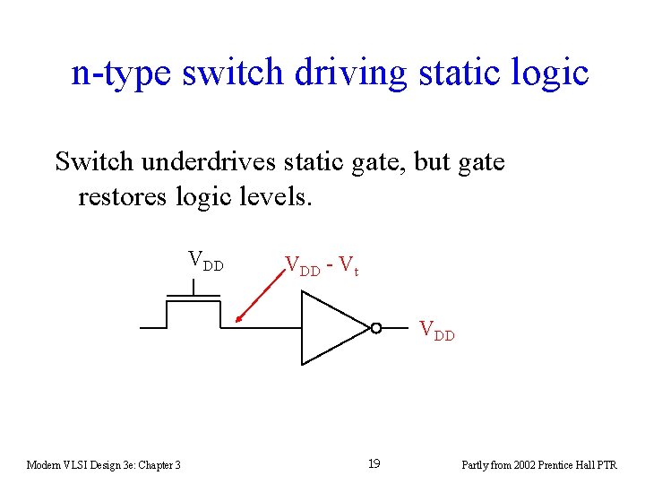
n-type switch driving static logic Switch underdrives static gate, but gate restores logic levels. VDD - Vt VDD Modern VLSI Design 3 e: Chapter 3 19 Partly from 2002 Prentice Hall PTR
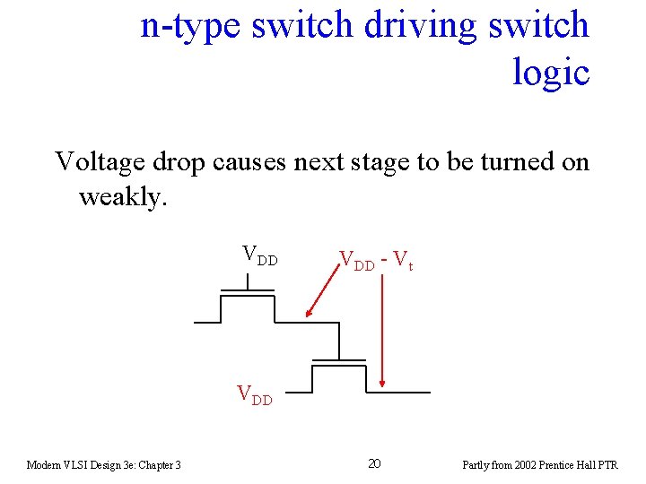
n-type switch driving switch logic Voltage drop causes next stage to be turned on weakly. VDD - Vt VDD Modern VLSI Design 3 e: Chapter 3 20 Partly from 2002 Prentice Hall PTR
Behavior of complementary switch n Complementary switch products full-supply voltages for both logic 0 and logic 1: – n-type transistor conducts logic 0; – p-type transistor conducts logic 1. Modern VLSI Design 3 e: Chapter 3 21 Partly from 2002 Prentice Hall PTR
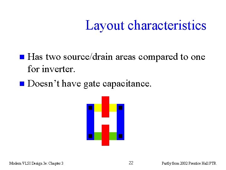
Layout characteristics Has two source/drain areas compared to one for inverter. n Doesn’t have gate capacitance. n Modern VLSI Design 3 e: Chapter 3 22 Partly from 2002 Prentice Hall PTR
Example 2 Modern VLSI Design 3 e: Chapter 3 23 Partly from 2002 Prentice Hall PTR
Modern VLSI Design 3 e: Chapter 3 24 Partly from 2002 Prentice Hall PTR