
Lecture planning Week 1 Briefing Chapter 1 Introduction

Lecture planning • • • Week 1 - Briefing Chapter 1 - Introduction Chapter 2 - Symbols Chapter 3 - Datums Chapter 4 - Concentricity symetricity Chapter 5 - Position Chapter 6 - Form, orientation, profile, runout Chapter 7 - Fit and tolerances Chapter 8 - Strategy for tolerancing part

Lecture planning • • Week 11 - Fit and tolerances Week 12 - Public Holiday Week 13 - Strategy for tolerancing part Week 14 - Project presentation + recap Week 15 - Project presentation + recap ----------------------------------Week 16 - Study week Week 17 - Final exam

GD & T Chapter 7 Strategy for tolerancing part
Rule #1 • The simplest meaning of rule #1 is at MMC the feature is on perfect form. For example consider a shaft with diameter Ø 5. 000 -Ø 5. 040. Then its MMC is Ø 5. 040. Now assume we have this part produced at Ø 5. 040 then according to rule #1 the part should be in perfect form. That is it should have perfect straightness, circularity and cylindricity.
Rule #2 • Rule #2 states that RFS automatically applies, in a feature control frame, to individual tolerances of size features and to datum features of size. MMC and LMC must be specified when these conditions are required. • Now examine rule #2, here also lets assume a stepped shaft with Ø 5. 000 and Ø 3. 000 -Ø 3. 004. The bigger diameter is assigned as datum (Say C) and the smaller diameter Ø 3. 000 is controlled by a concentric geometric tolerance and this tolerance is applied without any dimensional size constraints ie regardless of feature size (RFS)
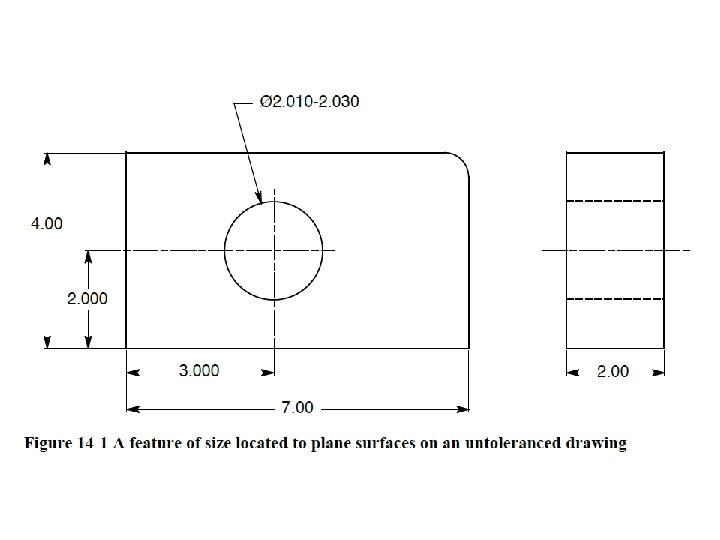
• The size tolerance of a feature not only controls its size but also controls its form, Rule #1. • According to the drawing in Figure 14 -1, the size of the 2. 000 -inch diameter hole can be made anywhere between 2. 010 and 2. 030 which means that the size tolerance is. 020. • However, if the machinist actually produces the hole at a diameter of 2. 020, according to Rule #1, the form tolerance for the hole is. 010, that is 2. 020 minus 2. 010. The hole must be straight and round within. 010. The hole size can be produced even larger up to a diameter of 2. 030, in which case the form tolerance is even larger. • If the form tolerance, automatically implied by Rule #1, does not satisfy the design requirements, an appropriate straightness and/or circularity tolerance must be specified.
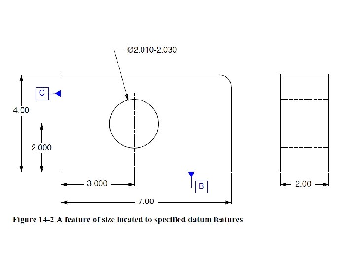
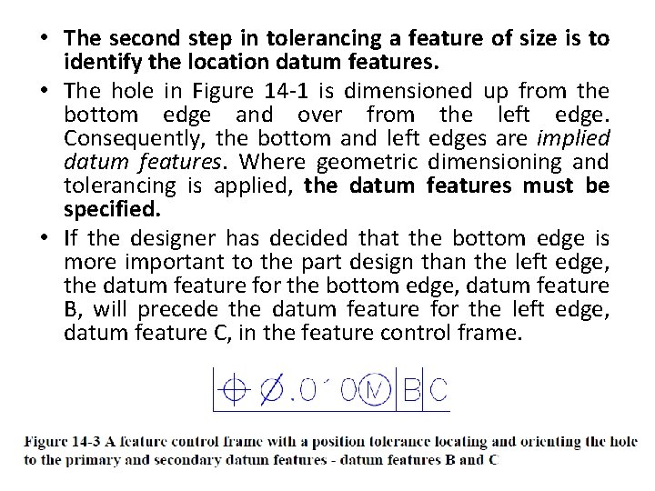
• The second step in tolerancing a feature of size is to identify the location datum features. • The hole in Figure 14 -1 is dimensioned up from the bottom edge and over from the left edge. Consequently, the bottom and left edges are implied datum features. Where geometric dimensioning and tolerancing is applied, the datum features must be specified. • If the designer has decided that the bottom edge is more important to the part design than the left edge, the datum feature for the bottom edge, datum feature B, will precede the datum feature for the left edge, datum feature C, in the feature control frame.
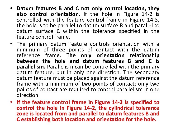
• Datum features B and C not only control location, they also control orientation. If the hole in Figure 14 -2 is controlled with the feature control frame in Figure 14 -3, the hole is to be parallel to datum surface B and parallel to datum surface C within the tolerance specified in the feature control frame. • The primary datum feature controls orientation with a minimum of three points of contact with the datum reference frame. The only orientation relationship between the hole and datum features B and C is parallelism. Parallelism can be controlled with the primary datum feature, but in only one direction. The secondary datum feature must be placed against the datum reference frame with a minimum of two points of contact; only two points of contact are required to control parallelism in one direction. • If the feature control frame in Figure 14 -3 is specified to control the hole in Figure 14 -2, the cylindrical tolerance zone is located from and parallel to datum features B and C establishing both location and orientation for the hole.
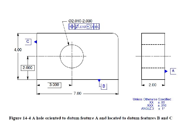
• The location tolerance between mating features comes from the difference between their size dimensions at MMC. • If a mating shaft 2. 000 inches in diameter at its MMC must fit through the hole in Figure 14 -4, the location tolerance can be as large as the difference between the 2. 010 diameter hole and the 2. 000 -inch diameter shaft for a positional tolerance of. 010. • A positional tolerance for locating and orienting features of size is always specified with a material condition modifier. The maximum material condition modifier (circle M) has been specified for the hole in Figure 14 -4. • The MMC modifier is typically specified for features in static assemblies. • The RFS modifier is typically used for high speed, dynamic assemblies. • The LMC modifier is used where a specific minimum edge distance must be maintained.
• Very often, the front or back surface, or both are mating features, and the hole is required to be perpendicular to one of these features. • If that is the case, a third datum feature symbol is attached to the more important of the two surfaces, front or back. • In Figure 14 -4, the back surface has been identified as datum feature A. Since datum feature A is specified as the primary datum feature in the feature control frame and the primary datum feature controls orientation, the cylindrical tolerance zone of the hole is perpendicular to datum feature A. • Where applying geometric dimensioning and tolerancing, all datum features must be identified, basic location dimensions must be specified, and a feature control frame is assigned.
• The primary datum feature is the most important datum feature and is independent of all other features. That is, other features are controlled to the primary datum feature, but the primary datum feature is not controlled to any other feature. • The only appropriate geometric tolerance for a primary datum feature is a form control. All other geometric tolerances control features to other features. • On complicated parts, it is possible to have a primary datum feature positioned to another datum reference frame. However, in most cases, it is best to establish only one datum reference frame per part.
• The primary datum feature is often a large flat surface that mates with another part, but many parts do not have flat surfaces. A large, functional, cylindrical surface may be selected as a primary datum feature. • Other surfaces configurations are also selected as primary datum features even if they require datum targets to support them. • In the final analysis, the key points in selecting a primary datum feature are: • Select a functional surface • Select a mating surface • Select a sufficiently large, accessible surface that will provide repeatable positioning
• Rule #1 controls the flatness of datum feature A in Figure 14 -4, since no other control is specified. • The size tolerance, a title block tolerance of ±. 030, a total of. 060, controls the form of the feature of size of which datum feature A is one side. • If Rule #1 doesn’t sufficiently control flatness, a flatness tolerance must be specified, and if the side opposite datum feature A must be parallel within a tolerance smaller than the tolerance allowed by Rule #1, a parallelism control must be specified as shown in Figure 14 -5. • If required, a parallelism control can also be specified for the sides opposite datum features B and C. Perpendicularity and parallelism specified for flat surfaces also control flatness within the same tolerance.
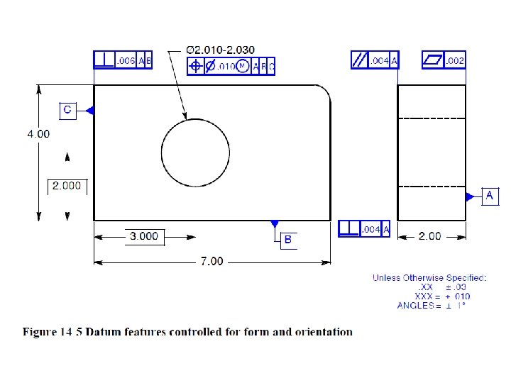
• In Figure 14 -5, datum feature B is specified as the secondary datum feature, that is the more important of the two location datum features. It may be more important because it is larger than datum feature C or because it is a mating surface. • When producing or inspecting the hole, datum feature B must contact the datum reference frame with a minimum of two points of contact. • The perpendicularly of datum features B and C to datum feature A and to each other is controlled by the ± 1° angularity tolerance in the title block if not otherwise toleranced. However, as shown in Figure 14 -5, datum feature B is controlled to datum feature A with a perpendicularity tolerance of. 004. • Datum feature C is specified as the tertiary (third) datum feature; it is the least important datum feature. When producing or inspecting the hole, datum feature C must contact the datum reference frame with a minimum of one point of contact. • The orientation of datum feature C may be controlled to both datum features A and B. For the 2. 000 -inch diameter hole in Figure 14 -5, datum feature A is the reference for orientation (perpendicularity) and datum features B and C are the references for location.
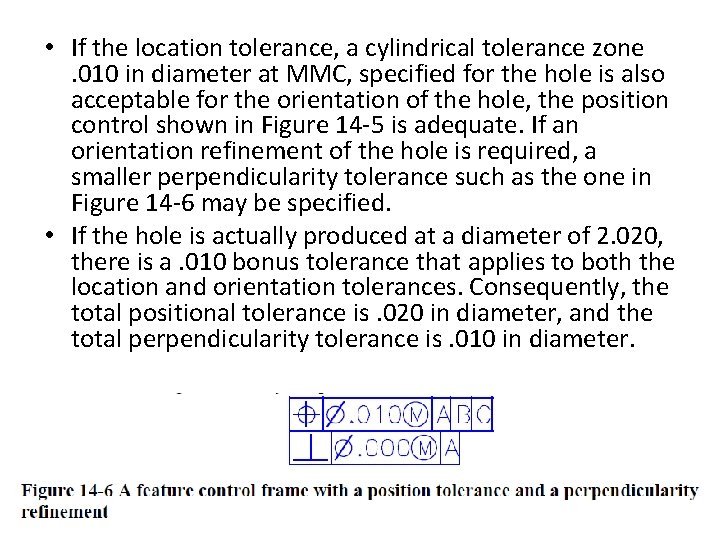
• If the location tolerance, a cylindrical tolerance zone . 010 in diameter at MMC, specified for the hole is also acceptable for the orientation of the hole, the position control shown in Figure 14 -5 is adequate. If an orientation refinement of the hole is required, a smaller perpendicularity tolerance such as the one in Figure 14 -6 may be specified. • If the hole is actually produced at a diameter of 2. 020, there is a. 010 bonus tolerance that applies to both the location and orientation tolerances. Consequently, the total positional tolerance is. 020 in diameter, and the total perpendicularity tolerance is. 010 in diameter.
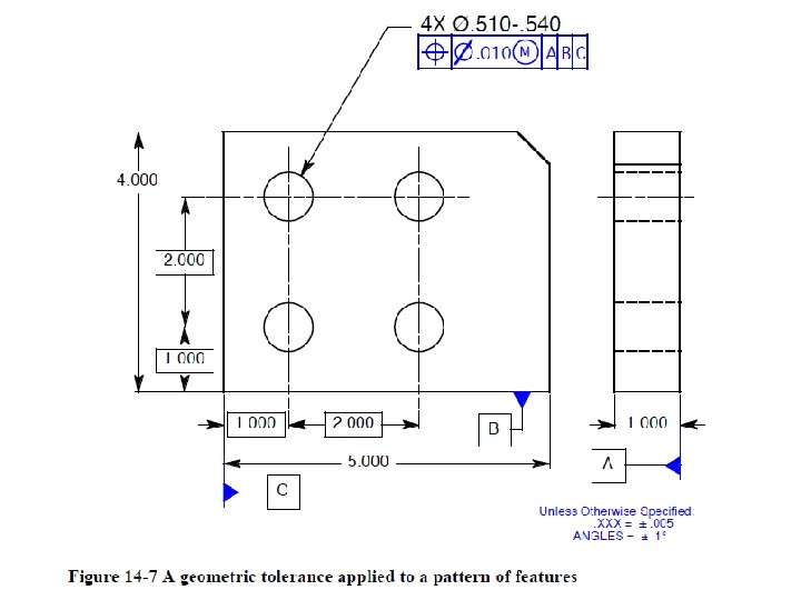
• The same tolerancing techniques specified for the single hole in the drawings above also apply to a pattern of holes shown in Figure 14 -7. • These holes are located and oriented to datum reference frame A, B, and C and to each other with basic dimensions. • The note, “ 4 X Ø. 510 -. 540” and the geometric tolerance apply to all four holes. The pattern of four cylindrical tolerance zones, . 010 in diameter at MMC, are located and oriented with basic dimensions to each other and to datum reference frame A, B, and C. The axis of each hole must fall completely inside its respective tolerance zone.

END

• Final • Saturday, 11 june (9 am-12 pm) • BK 7 and BK 9
- Slides: 23