Lecture planning Week 1 Briefing Chapter 1 Introduction

Lecture planning • • • Week 1 - Briefing Chapter 1 - Introduction Chapter 2 - Symbols Chapter 3 - Datums Chapter 4 - Concentricity symetricity Chapter 5 - Position Chapter 6 - Form, orientation, profile, runout Chapter 7 - Fit and tolerances Chapter 8 - Strategy for tolerancing part

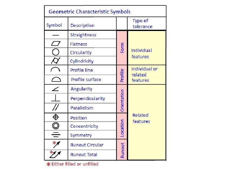
G D & T Chapter 4 Concentricity & symetricity

Chapter objectives • 4. 1 Define concentricity and symmetry • 4. 2 Describe the inspection process of concentricity and symmetry • 4. 3 Explain applications of concentricity and symmetry

Concentricity

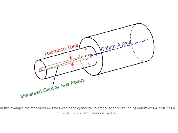
Concentricity, sometimes called coaxially, is a tolerance that controls the central axis of the referenced feature, to a datum axis. Concentricity is considered one of the most difficult GD&T symbols to measure for due to its difficulty in establishing the mid points of the feature. First you must establish a datum axis which to measure, Once the datum axis is established you must now take measure many a series of cross sections

An intermediate shaft in a transmission is composed of two different diameter sections which are coaxial. Datum A is the drive side and relatively fixed with bearings to the housing, The referenced surface B is desired to be concentric with Datum A to avoid oscillations at high speed.

What is concentricity • Concentricity is that condition where the median points of all diametrically opposed points of a surface of revolution are congruent with the axis (or center point) of a datum feature. • Concentricity applies to correspondingly located points of two or more radically disposed features, such as the flats on a regular hexagon, or opposing lobes on features such as an ellipse. • Verifying concentricity is a time-consuming process, and in many cases it is recommended to use runout or position tolerance.
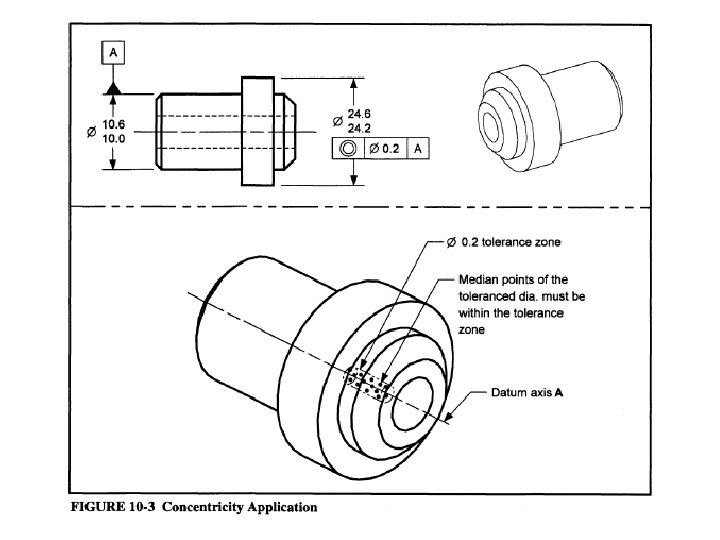

Interpretation • Concentricity controls all median points of all diametrically opposed points on the surface of the toleranced feature. • The aggregate of all median points, sometimes described as a “cloud of median points, ” must lie within a cylindrical tolerance zone whose axis is coincident with the axis of the datum feature. • The concentricity tolerance is independent of both size and form. • Differential measurement excludes size, shape, and form while controlling the median points of the feature.

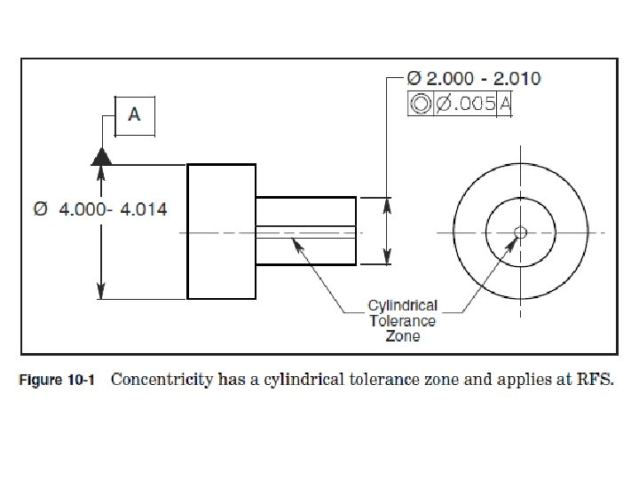
The feature control frame in Fig. 10 -2 specifies a cylindrical tolerance zone. 005 in diameter and coaxial with the datum axis. Differential measurements are taken along and around the toleranced feature to determine the location of its median points. If all median points fall inside the tolerance zone, the feature is in tolerance.

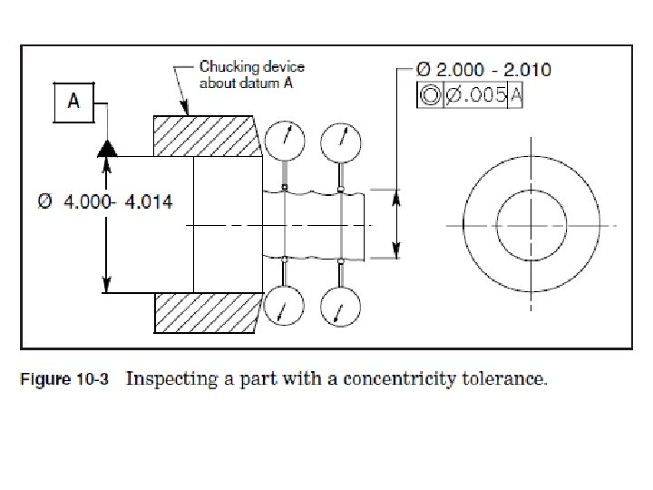
Inspection • Concentricity can be inspected, for acceptance only, by placing a dial indicator on the toleranced surface of revolution and rotating the part about the datum axis. • If the full indicator movement (FIM) on the dial indicator does not exceed the specified tolerance, the feature is acceptable. • This technique is a simple first check that will accept parts but will not reject them, and it can be used only on surfaces of revolution.

• If the measurement does exceed the FIM, the part is not necessarily out of tolerance. To reject a part with a concentricity tolerance, the datum is placed in a chucking device that will rotate the part about its datum axis. • A point on the surface of the toleranced feature is measured with a dial indicator. The part is then rotated 180◦ so the diametrically opposed point can be measured. • The difference between the measurements of the two points determines the location of the median point. This process is repeated a predetermined number of times. • If all median points fall within the tolerance zone, the feature is in tolerance.

• Concentricity is considered one of the most difficult GD&T symbols to measure for due to its difficulty in establishing the mid points of the feature. First you must establish a datum axis which to measure, Once the datum axis is established you must now take measure many a series of cross sections.

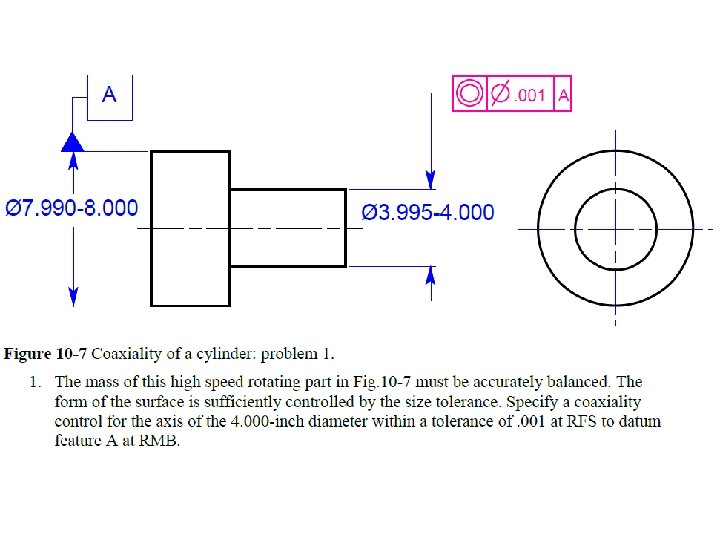
Application of Concentricity • Concentricity is normally specified for high-speed rotating parts, rotating mass, axis-to-axis precision, or any other feature critical to function. • Concentricity is considered when critical axis-to-axis control is required for dynamically balanced features. • Runout also control balance, but it controls form and surface imperfections at the same time. It easy and in expensive to inspect, but manufacturing is more difficult and costly. • Concentricity is time-consuming and expensive to inspect but less expensive to manufacture.

Symmetry

What is symmetry • Symmetry is the condition where a feature or part has the same profile on either side of the center plane (median plane) of a datum feature. • Symmetry is specified for features to be located (location control) symmetrically with respect to the median plane of a datum feature. It may also be specified for a feature in a common plane with a datum plane. Symmetrical parts are usually easier to assemble, look better and help maintain balance in a design.

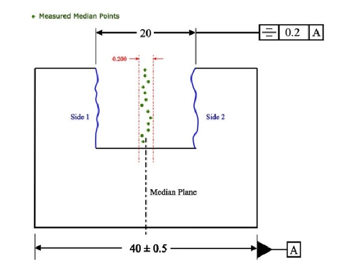
Symmetry GD&T Symmetry is a 3 -Dimensional tolerance that is used to ensure that two features on a part are uniform across a datum plane. An established “true” central plane is established from the datum and for the symmetry to be in tolerance, the median distance between the every point on the two surface features need to fall near that central plane.

Features shown symmetrical must be controlled to avoid incomplete drawing requirements.

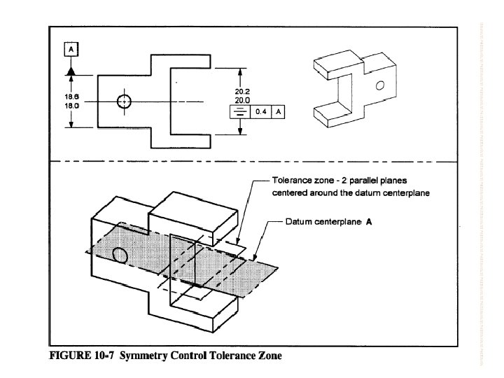
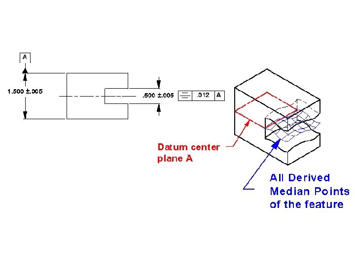
Interpretation • Symmetry controls the median points of all opposed or correspondingly located points of two or more surfaces. • The aggregate of all median points, sometimes described as a “cloud of median points, ” must lie within a tolerance zone defined by two parallel planes equally disposed about the center plane of the datum feature, i. e. , half of the tolerance is on one side of the center plane, and half is on the other side. • The symmetry tolerance is independent of both size and form. • Differential measurement excludes size, shape, and form while controlling the median points of the feature.

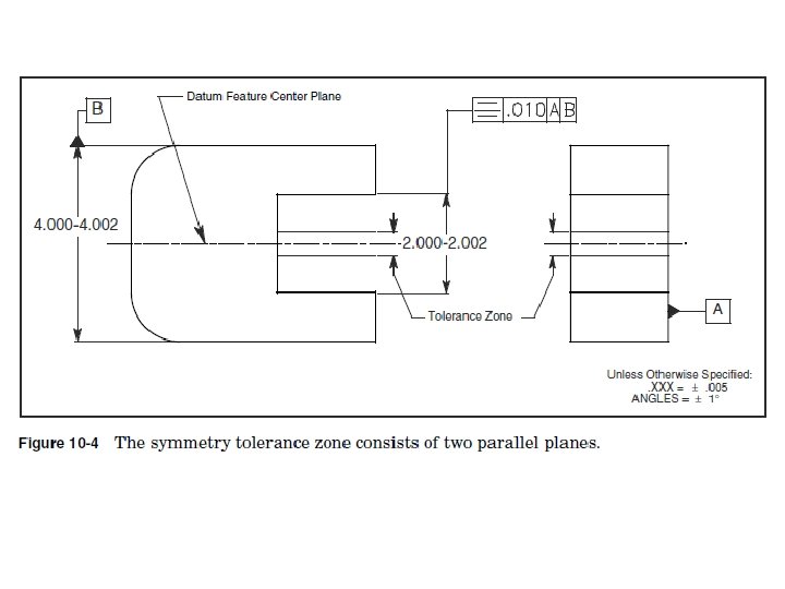
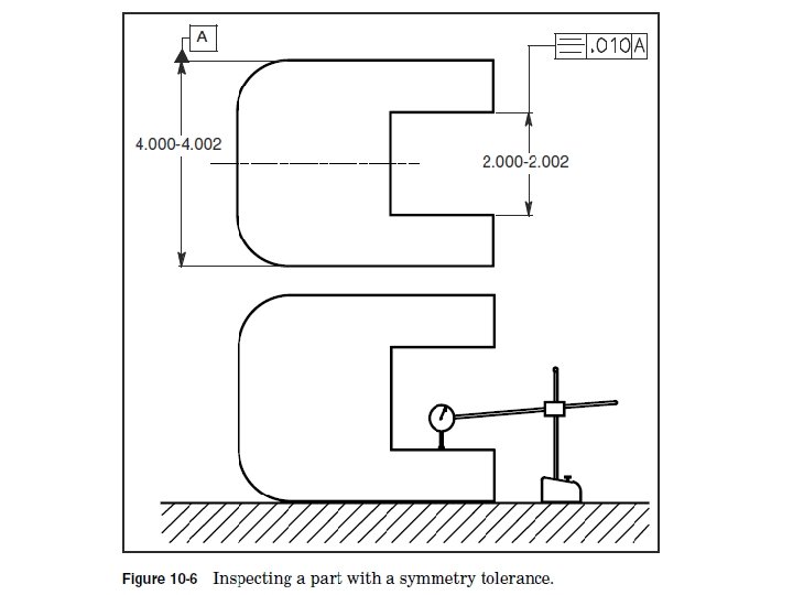
The feature control frame in Fig. 10 -5 specifies a tolerance zone consisting of two parallel planes. 010 apart, perpendicular to datum plane A, and equally disposed about datum plane B. Differential measurements are taken between the two surfaces to determine the location of the median points. If all median points fall inside the tolerance zone, the feature is in tolerance.

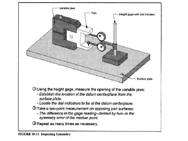
Inspection • This method can be used only if the datum surfaces are parallel compared to the symmetry tolerance. • In this example, one of the datum surfaces is placed on the surface plate. • A dial indicator is used to measure a number of points on the surface of the slot. These measurements are recorded. • The part is turned over, and the process is repeated. The measurements are compared to determine the location of the median points and whether or not the feature is in tolerance.

Application • The symmetry tolerance is often used to accurately control balance for rotating parts or to insure equal wall thickness. Specify symmetry only when it is necessary because it is time-consuming and expensive to manufacture and inspect. • The symmetry control is appropriately used for large, expensive parts that require a small symmetry tolerance to balance mass. If the restrictive symmetry control is not required, a more versatile position tolerance may be used to control a symmetrical relationship.

END
 • Staple")
Assignment • Must be hand written. • Due date: 24/3/16 (week 6) • Staple with the given front page.
- Slides: 36