LECTURE NINE WIRE DRAWING PROCESS Introduction In drawing


 Process variables in wire drawing. The die angle, the reduction in")


; μ = die-work coefficient of friction;")
- Slides: 8
LECTURE NINE WIRE DRAWING PROCESS
Introduction In drawing, the cross section of a long rod or wire is reduced or changed by pulling (hence the term drawing) it through a die called a draw die (Fig. 9. 1). Thus, the difference between drawing and extrusion is that in extrusion the material is pushed through a die, whereas in drawing it is pulled through it. Drawing is a term also used in sheet metalworking. The term wire and bar drawing is used to distinguish the drawing process discussed here from the sheet metal process of the same name. Rod and wire products cover a very wide range of applications, including shafts for power transmission, machine and structural components, blanks for bolts and rivets, electrical wiring, cables, . . Etc.
Fig (9. 1) Process variables in wire drawing. The die angle, the reduction in cross sectional area per pass, the speed of drawing, the temperature and the lubrication all affect the drawing force, F
The major processing variables in drawing are similar to those in extrusion that is, reduction in cross-sectional area, die angle, friction along the die-workpiece interface, and drawing speed. The die angle influences the drawing force and the quality of the drawn product. The basic difference between bar drawing and wire drawing is the stock size that is processed. Bar drawing is the term used for large diameter bar and rod stock, while wire drawing applies to small diameter stock. Wire sizes down to 0. 03 mm (0. 001 in) are possible in wire drawing. Bar drawing is generally accomplished as a single-draft operation—the stock is pulled through one die opening. Because the beginning stock has a large diameter, it is in the form of a straight cylindrical piece rather than coiled. This limits the length of the work that can be drawn. By contrast, wire is drawn from coils consisting of several hundred (or even several thousand) feet of wire and is passed through a series of draw dies. The number of dies varies typically between 4 and 12.
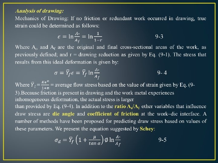
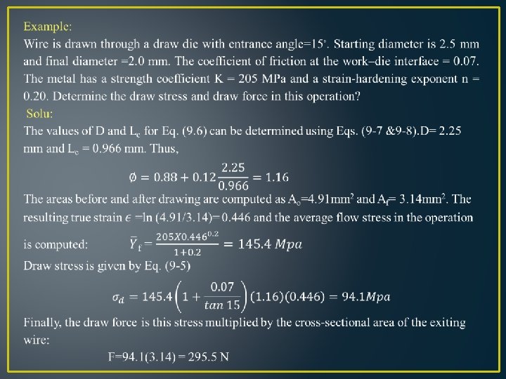
Where σ_d = draw stress, MPa (lb/in 2); μ = die-work coefficient of friction; α = die angle (approach angle) (half-angle) as defined in Figure (9. 1); and ∅ is a factor that accounts for inhomogeneous deformation which is determined as follows for a round cross section: ∅=0. 88+0. 12 D/L_c 9 -6 Where D= average diameter of work during drawing, mm(in); and Lc = contact length of the work with the draw die in Figure (9. 1), mm(in). Values of D and Lc can be determined from the following: D=(D_°+D_f)/2 9 -7 L_c=(D_°-D_f)/2 sinα 9 -8 The corresponding draw force is then the area of the drawn cross section multiplied by the draw stress: 9 -9 Where F = draw force, N (lb); and the other terms are defined above. The power required in a drawing operation is the draw force multiplied by exit velocity of the work.