Lecture 9 Dimitar Stefanov Recapping DC and AC


 The")
 üElectrode part (Ag/Ag. Cl electrodes)")

 • There are")
 (All electrodes")


 socket design Ultrasonic and computer tomography – future aspects")

- Slides: 27
Lecture 9 Dimitar Stefanov
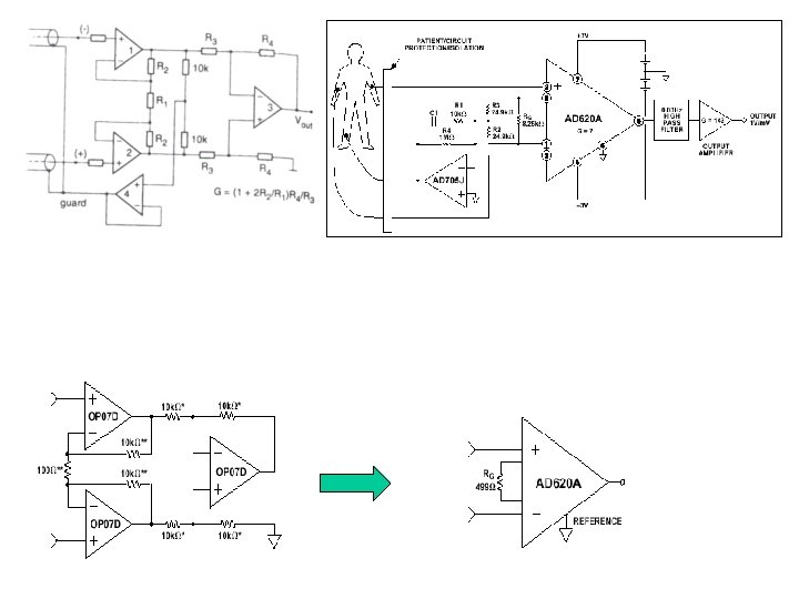
Recapping DC and AC instrumentation amplifiers: • Errors due to the capacitance of the shielded wires that connect electrodes with the amplifier • The capacitors between the electrodes and the input stage of the amplifier cause charging effects from the input bias current. • Solution of the problem: Input guarding
Differential Shield Driver Common-Mode Shield Driver 5 mm X 4 mm X 1. 75 mm !
Techniques which eliminate` the influence of the capacitance of the connective electrode wires
Best elimination of the capacitance – if no wires are used. Bipolar Concentric ring sensor for surface Laplacian ECG (University of Miami) Double-sided 13 x 13 mm PC board The contact area of the outer ring and the inner dot are equal. More information: M. Talero, C. C. Lu, Active Bipolar Concentric Ring Sensor for surface Laplacian ECG, in the Proc. First BMES/EMBS conference on Serving Humanity, Advancing Technology, Oct. 13 -16, 1999, Atlanta, GA, USA
Tripolar electrode sensor for Laplacian cardiograms (University of Miami, Department of Biomedical Engineering) The sensor contains three closely spaced rings. The width of each ring is 1. 0 mm. The diameters of the outer ring and the middle ring are 36 mm and 18 mm respectively. The ring/dot in the center is 2. 0 mm in diameter. An instrumentation amplifier with an input impedance of 10 Gohms is used. Further information: http: //sbec. abe. msstate. edu/abstracts/lu. htm
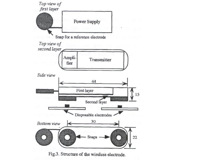
Wireless electrodes for surface electromyography (Keio University – Japan) üElectrode part (Ag/Ag. Cl electrodes) + amplifier + high-pass filter + built-in transmitter + battery üInstrumentation amplifier AD 620 BR üFM transmitter üfive button battery cells ü 20 m distance between the electrodes and the receiver ü 15 hours operation with one set batteries.
Before transmission After transmission More information: M. Ohyama, Y. Tomita, S. Honda, H. Uchida, and N. Matsuo, Active wireless electrodes for surface electromyography, Proc. Of the 18 th Annual International Conference of the IEEE EMBS, Amsterdam, 1996, pp. 295 – 296.
Micro system for sensing of biological parameters (Waseda University – Japan) • There are no wire lines between the sensors and the transmitter. One transmitter, located on the wrist, is used for transmission of the data from all sensors. • Between the detector part and the transmitter, the signals are sent as a AC micro current flow through the tissue of the body.
ECG monitoring system The dipole map for the heart from Waller (1889) (All electrodes are mounted on a common frame. The distance between the electrodes is 5 cm. )
A. / Block diagram of the ECG detector transmitter Sampling frequency – 900 Hz Carrier frequency – 70 k. Hz (sinusoidal signal)
B. / Block diagram of the relay transmitter C. / Transmission of the signals between the ECG transmitter and the relay transmitter (transmission of the signal in the human body): Tissue equivalent circuit
Equivalent circuit of the tissue-electrodes contour
D. / Frequency characteristic The distance between the electrodes RF and T (electrodes where the signals are applied) is 7 cm. The distance between the electrodes B, S and T (electrodes for detection of the signals) is 3 cm. In case of two channels, two carrier frequencies are chosen: 50 k. Hz and 70 k. Hz. More information: T. Handa, S. Shoji, S. Ike, S. Takeda, and T. Sekiguchi, A Very low-power consumption wireless ECG monitoring system using body as a signal transmission medium, Proc. Transducer’ 97 - Int. Conf. On solid-state sensors and actuators, Chicago, June 16 -19, 1997 Eiji Takeda, Takashi Handa, Shuichi Shoji, Akihiko Uchiyama, STUDIES ON BIO-SENSING MICROSYSTEMS FOR HEALTH CARE, XIV International Symposium on Biotelemetry, Marburg, Germany April 6 - 11, 1997, http: //baby. indstate. edu/isb/publications/abstracts/session 3 -6. htm
Prosthetics and Orthotics Amputations Result of: • Decrease in blood supply to the muscles and periphery (diseases of the arteries to the limbs or diabetes). • Automobile and motorcycle accidents • Bone cancers and tumors • Direct trauma (train wheels, power saw) • Osteomyelitus and other infections • War and natural disasters. Prosthesis – device which replaces a part of the functions of a missing limb.
Prosthetics and Orthotics Orthosis – device which is applied to the exterior of the body to stabilize or enhance motion of a limb or joint. Functions of the orthoses : • to reduce the stress on body parts; • to protect of diseased or injured limbs • to prevent or correct skeletal deformities; • to stabilize joints.
- Post-operative treatment for amputations Temporary prostheses – applied after the surgical operation and minimize loss of sensory motor coordination. Prosthesis - example socket (individually fitted component) residual limb (soft tissue and bones)
Orthosis - example Classification of the prostheses: 1. 2. 3. 4. Upper-limb and lower-limb prostheses Functional and cosmetic prostheses Body-driven and external-power-driven prostheses (body-operated, cablecontrolled, electrically operated) External power: electrical power (batteries), pneumatic and hydraulic driven (some old models)
Classification based on the level of amputation : 1. Upper-limb prostheses can be classified as shoulder disarticulation prostheses, above-elbow (AE) prostheses, below-elbow (BE) prostheses 2. Lower-limb prostheses can be classified as above-the-knee (AK) prostheses and below-theknee (BK) prostheses
Functional classification of orthoses: 1. 2. 3. 4. Immobilization or stabilization of joints and limbs (A) Prevention of skeletal and joint deformations (B) Chance of the position of a body part (traction) in case of weak muscle performance (C). tremor-suppression orthosis (D). B A C
Tremor-suppression orthosis Jack Kotovsky and Michael J. Rosen, A wearable tremor-suppression orthosis, in the Journal of Rehabilitation Research and Development, Vol. 35 No. 4, October 1998, pp. 373 -387 The orthosis damps wrist flexion and extension tremor. constrained layer damping (CLD) Fluid damping Pneumatic damping • Active damping orthoses - permits electrically tunable damping. • Piezoelectric or electro-rheological (ER) damping elements - their damping properties may be controlled with an applied voltage.
Prosthesis = functionality + good cosmetic appearance Energy sources: • External power – electric, pneumatic and mechanical • Body power. Actuators: electromotor, piston, “Mc. Kibben” artificial muscle Prosthesis fitting Design of customized components to match to body shape. Socket: • most critical element of the prosthesis: • individually fitted component of the prosthesis • in contract with the residual limb. Fitting: • casting the residual limb – a cast of the residual limb is used to make a socket for the prosthesis. • CAD-CAM methods
Illustration of CAD-CAM above-knee (AK) socket design Ultrasonic and computer tomography – future aspects of the CAD-CAM socket design • Instead of casting, a non-invasive imaging process is applied. • The external shape and the external tissue structure of the residual limb are recorded.
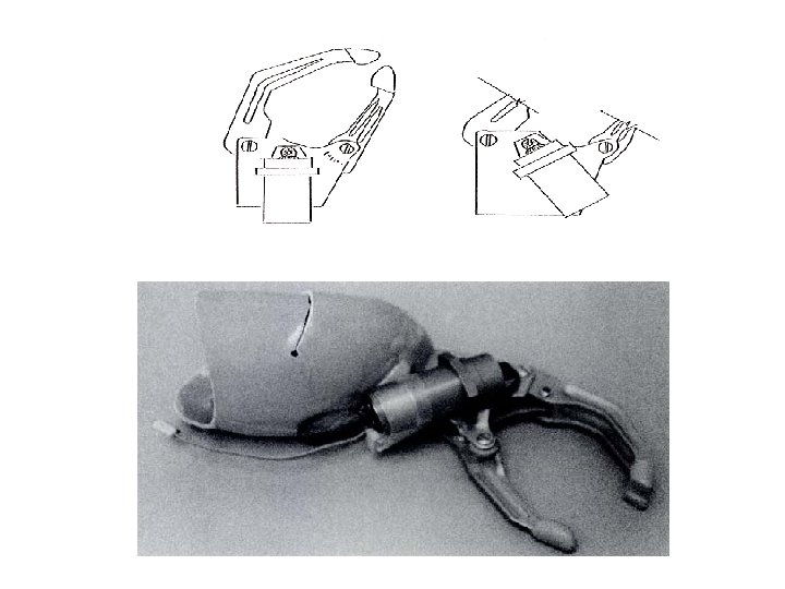
• Prosthesis often can be made lighter than the limb it replaces. • Prosthesis length – near the length of the natural limb. Upper-extremity prostheses Terminal devices allow grasping functions Internally or externally powered Mechanical hook Voluntary opening and closing Cosmetic glove to a hook