Lecture 8 SSR Mode S Uplinkformats in Mark


. The")

 is set by a")
 pulse is used by air traffic controllers to confirm")


 project, later renamed Mode")


 - Interrogation Path Side Lobe")


 Mode S/ES")


")

 • Incorporates mode A/C ability … plus … • Less power")
 • As for mode S plus … • Periodically broadcasts")

 • Automated system which alerts ATC • Requires transponders")
 • • • Is an Airborne Collision Avoidance")


 Recommendations • Strategy for")
 • On 1090 MHz channel – Secondary")
 • Squitters – Aircraft broadcast non-solicited long")


 – Example of Navigation (FMS),")
- Slides: 80
Lecture 8 SSR Mode S
Uplink-formats in Mark X Standard
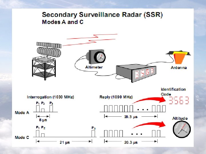
The Reply Message The SSR down link format consists of a number of pulses, nominally 0. 45 µs (± 0. 1 µs). F 1 and F 2 are always present and separated by 20. 3 µs (± 0. 1 µs) – they are often referred to as a bracket or framing pair. Other pulse positions within this framing pair are spaced by 1. 45 µs and are used to convey the required reply information in answer to the specific interrogation (e. g Mode A identity or Mode C flight level values).
The pulses are identified to give the bits of an octal code (ABCD). The X pulse at the centre of the reply is not used. The three blank positions may not be occupied by pulses, otherwise some decoders may reject the entire answer as interference. Note that the reply information itself does not contain any information to indicate which mode it is a reply to. The interrogator will assume that the replies received are in answer to it latest mode of interrogation.
SSR down link format
In the case of Mode A, the octal code (ABCD) is set by a control panel in the cockpit. In the case of mode C, the flight level is encoded in a special way (by a special form of Gray code known as Gillham code - this has the characteristic of only one bit changing for each change in flight level).
The SPI (Special Purpose Identification) pulse is used by air traffic controllers to confirm the identity of certain aircraft. The controller will ask the pilot to squawk ident – the pilot pressing a button on the control panel which adds the SPI pulse to SSR replies for a certain period (18± 1 s).
The display system will then highlight aircraft with SPI. (The SPI pulse may have been appropriate to distinguish aircraft on older display systems before fully plot extracted displays became available). The out of frame position of the SPI pulse is somewhat strange and, as will be seen later, the SPI pulse position chosen introduces rather unfortunate complications for automatic decoding purposes. According to ICAO the SPI-pulse will be added to Mode A reply only.
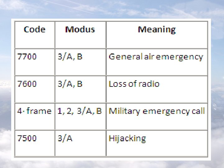
Each answer receives its meaning only in connection with the respective question. For example: - 7700 in Mode 3/A: general air emergency - 7700 in Mode C: 20, 000 ft height
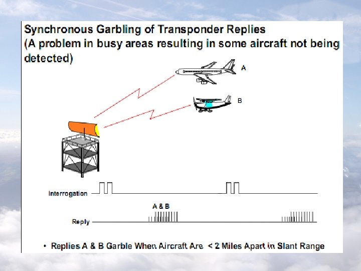
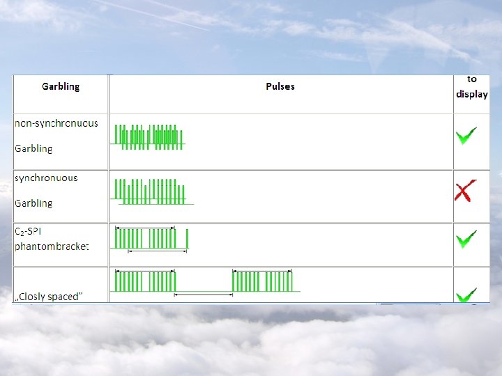
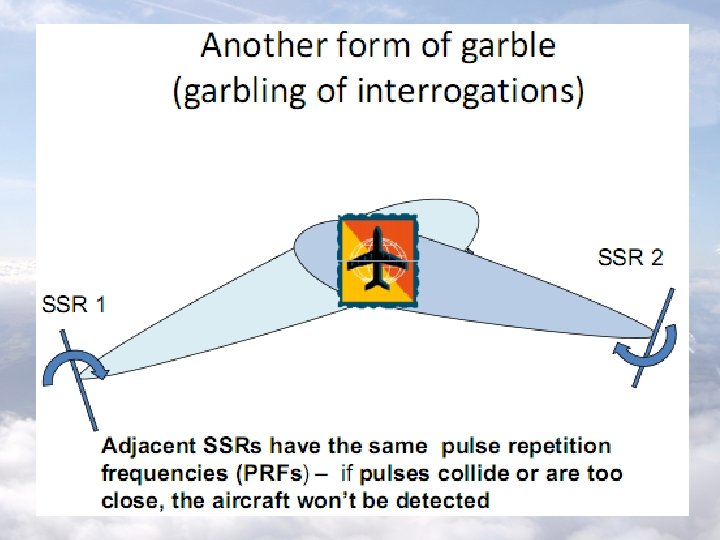
Garbling/Degarbling Garbling is a fundamental problem in the design of the classical SSR system and the situation is made worse by increased traffic. Aircraft are often closely spaced in range and azimuth but at different heights. Replies from two aircraft will overlap if their range separation is within the equivalent of the 20. 3 µs reply length. This is approximately 1. 7 Nm.
The most serious garbling situations occur when the azimuth separation is very small such that replies from both aircraft are received from all interrogations across the beam. With advanced reply processing techniques and algorithms, it may sometimes be possible to extract all some or all of the replies from the received signal.
At this, in principle, one distinguishes two manners of the overlapping: - Non-synchronous Garbling; - Synchronous Garbling Two replies overlaps in time such that its time grids are not congruent, so one speaks about Non-synchronous Garbling. Such answers can be separated and one by one be decoded correctly!
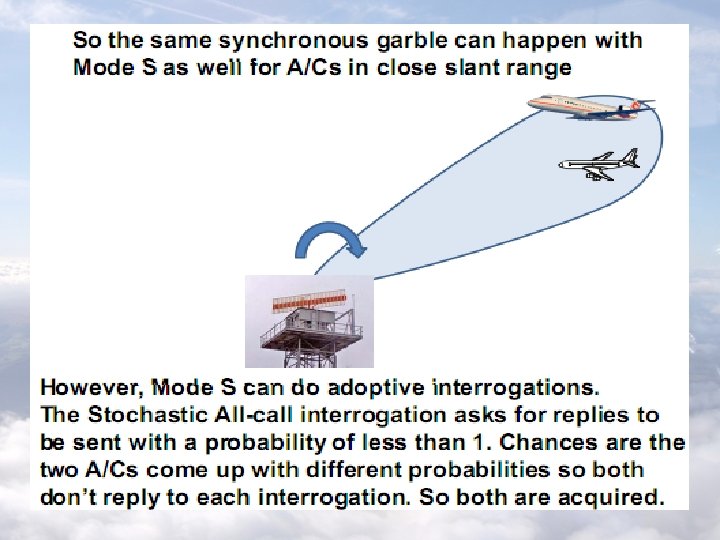
Synchronous garbling
But if two or more replies overlap in time such that its time grids are congruent, so one speaks about Synchronous Garbling. It cannot to state in the decoding any more, whether this single impulse belongs to one or the other ones response telegrams. Through this it would come to the decoding of completely new and wrong replies and difficult from the original replies. These replies must therefore be disabled!
Super Mode S Beacon • Discrete Address Beacon System (DABS) project, later renamed Mode S • Enable two way ground-air data transmission • S = Select: Uses discrete addressing to interrogate just one aircraft
Overview reply interrogation
Mode S
Interoperability Issues • Transparency: Mode S must not break existing systems • Backwards-compatibility: Existing systems must still see Mode S equipped planes other aircraft existing signal existing ground station Mode S equipped new signal Mode S ground station
Frequency • New frequency: difficult to allocate • Same frequency as old system (1030/1090 MHz): interoperable, but may cause interference 300 MHz VHF 1030 MHz 1090 MHz UHF 3000 MHz SHF
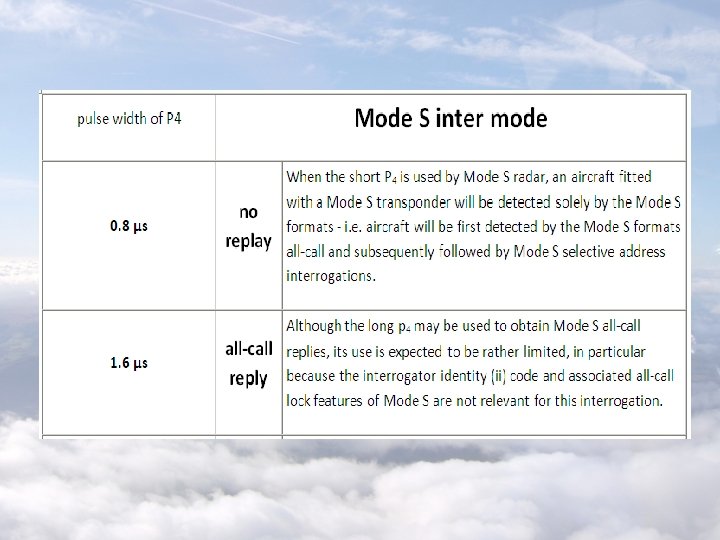
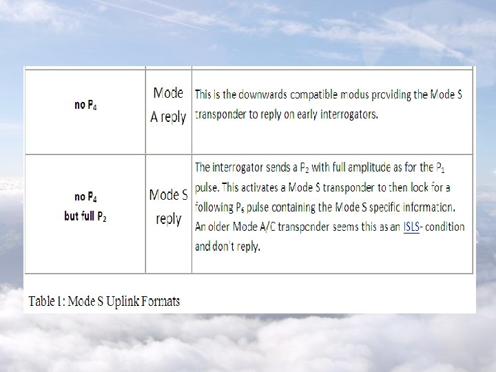
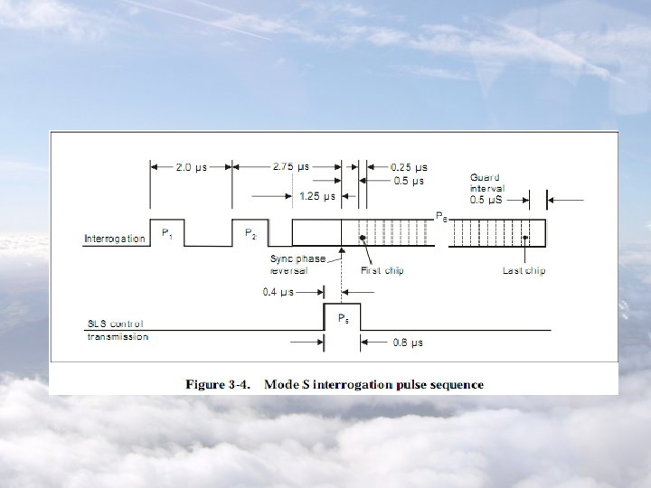
Mode S Uplink Formats A conventional SSR interrogator may have a typical sequence of Mode A interrogation, followed by Mode C interrogation or other modes. This would be repeated continually at a high rate to ensure that a position/identity plot can be produced for all targets in line-of-sight range of the interrogator during each antenna revolution.
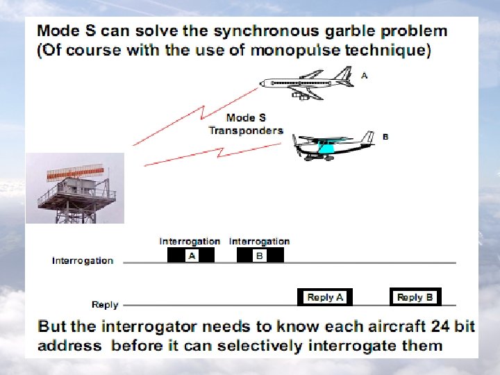
The Mode S ground station produces a larger variety of interrogation types. These types can be roughly classified into two types: - All-call interrogations - Roll-call interrogations
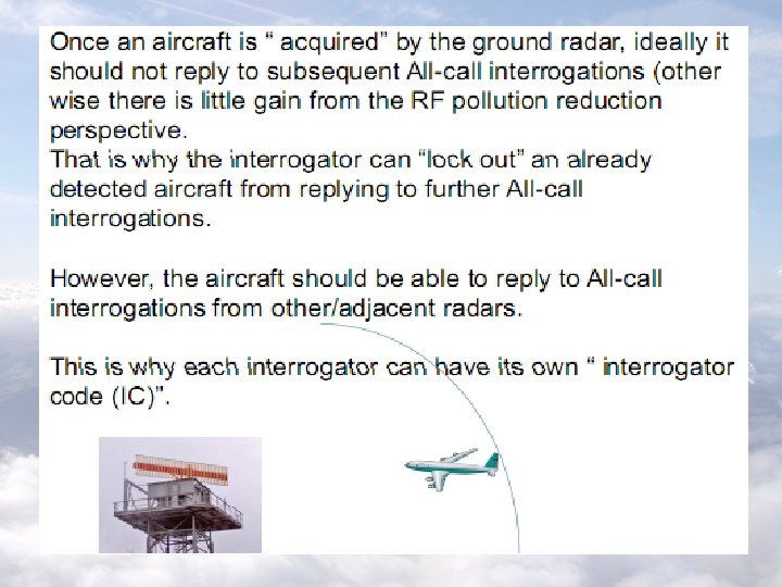
All-call interrogations obtain replays from all aircraft in the beam dwell, although, under certain circumstances, Mode S aircraft can be „locked out” to all interrogations so that they do not reply. Roll-call interrogations are selectively addressed to acquired Mode S equipped aircraft using the unique 24 bit address assigned to each aircraft. Only the addressed aircraft produce replies.
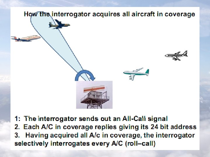
The first problem for the Mode S system is to find the addresses of aircraft that are in radar cover so that selective addressed interactions can be made with them. This is achieved by Mode S all-call interrogator witch are made periodically from the radar.
Transponders • Standard doesn’t specify what ATCRBS transponders should not do: – 549 transponders on the market – Each had unique behavior
Side Lobe Suppression In secondary surveillance radar technology the side lobes of the antennae affect particularly unfavorably. Transponders also can be interrogated over the side lobes and then answer about these, too and a response telegram can be received also over the side lobes. This circumstance results from the fundamentally better transmitting- and reception conditions for secondary radar units.
Such answers cannot be assigned obviously on the radar screen. They rather appear as several targets in the same range but in different directions. In the extreme case an airplane can be interrogated permanently during a turn of the antenna. Such an reply then appears on the PPI-scope as a „ring around”.
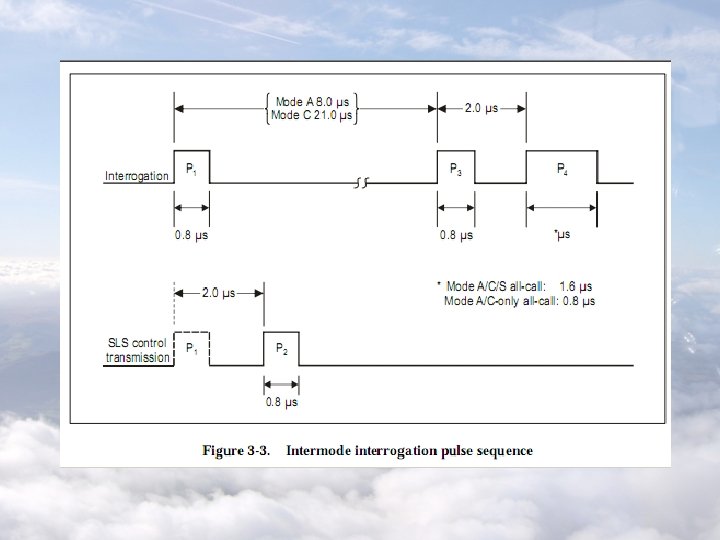
There are two principles of Side Lobe Suppression (SLS) - Interrogation Path Side Lobe Suppression (ISLS), and - Reply Path Side Lobe Suppression (RSLS) The techniques for ISLS are very similar to those for RSLS. A supplementary so called - Improved Interrogation Path Side Lobe Suppression (IISLS) method uses the techniques of ISLS to reduce the influence of false replays caused by reflection.
The Hack aircraft 1 ground station n lo ai P 1 m - Existing ATCRBS transponders used sidelobe suppression be aircraft 3 be lo side INTERFERENCE!!! aircraft 2
The Hack aircraft 1 aircraft 3 A 1 P 2 P 1 m ai n lo be - Existing ATCRBS transponders used sidelobe suppression be lo side ground station P 2 A 2 P 1 P 2 aircraft 2
Hacking the Hack - Purposely send a small P 1 and large P 2 - “Disables” ATCRBS transponders - Use the time to cram in Mode S data blocks - Limited number of bits can be sent in this window P 1 P 2 Mode S data block 35 microseconds
What Changed Things • Mid-air collision in 1986 • Congress passes a law mandating that all commercial aircraft be equipped with a Traffic Collision and Avoidance System (TCAS) by 1993 – TCAS uses Mode S – TCAS is now an international standard • Mode S technology is now commercially available
Mode S Today • 108 of the U. S. ’s busiest airports have Mode S ground stations • Majority of aircraft landing at these airports have Mode S transponders • Without Mode S, the 1030/1090 Mhz band would be completely overloaded • Mode S used in TCAS and many other applications
Transponder Basics
Overview • • • Secondary Surveillance Radar Mode A/C Mode S (selective) Mode S/ES (extended squitter) ADS-B (Automatic Dependent Surveillance Broadcast) • STCA (Short Term Conflict Alert) • TCAS (Traffic alert Collision Avoidance System) • Flarm
Acronyms • • • • ACAS – Airborne Collision Avoidance System ADS-B – Automatic Dependent Surveillance Broadcast CAT – Commercial Air Traffic EHS – (Mode S) Enhanced Surveillance ELS – (Mode S) Elementary Surveillance ES – Extended Squitter GA – General Aviation LAST – Light Aviation SSR Transponder LPST – Low Power SSR Mode-S Transponder SSR – Secondary Surveillance Radar STCA – Short Term Conflict Alert TCAS – Traffic alert Collision Avoidance System TMZ – Transponder Mandatory Zone TRA(G) – Temporary Reserved Areas (Gliders) UAV – Unmanned Aerial Vehicle
Secondary Surveillance Radar • • • Primary radar relies on passive reflection Secondary radar co-located with primary SSR beam interrogates transponders Transponder reply depends on its mode ATC computers use SSR to tag primary echoes with identifier and height
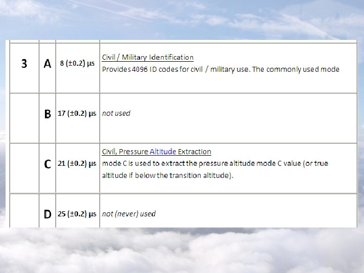
Mode A • Developed from 2 nd World War IFF (Identification Friend or Foe) • Limited number of squawk codes (4096) • Non-selective – all transponders respond to every interrogation broadcast • Typically high power requirements: – Frequent transmissions – Power hungry transmitter
Mode A/C • Incorporates mode A … plus … • Altitude (i. e. Flight Level) as well as identifier • Extra power required to heat the altimeter to a constant temperature
Mode S (selective) • Incorporates mode A/C ability … plus … • Less power required because: – Transmitter is typically more efficient – Altimeter does not need a heater • Can respond selectively: – If the SSR interrogates selectively – Can reduce power even more • Two levels of function (and price!): – ELS: Elementary Surveillance (gliders & light aircraft) – EHS: Enhanced Surveillance (for CAT)
Mode S/ES (extended squitter) • As for mode S plus … • Periodically broadcasts GPS position & velocity • Potentially provides one half of an airborne collision avoidance system • Provides some interoperability with ADS-B
ADS-B • Broadly equivalent to Mode S/ES • 150 mile range • Does not need a ground-based radar system • Already in use in Alaska & Australia • Arguably the system of the future
STCA (Short Term Conflict Alert) • Automated system which alerts ATC • Requires transponders on both aircraft • Requires at least one aircraft to be in contact with ATC
TCAS (Traffic alert Collision Avoidance System) • • • Is an Airborne Collision Avoidance System Receives transponder signals Works with mode A/C, S, or S/ES Mandatory for CAT Useless at detecting non-transponder aircraft
Flarm • • Good value collision avoidance 11, 000 in use High take up in the Alps and Germany Growing take up in UK Short range (a few kilometres) Ideal for gliders and slow speed aircraft May be unsuitable for ATC or CAT Unacceptable as an alternative to mode S
ASAS Enabling technologies Aircraft Sensors ASAS Display TIS-B ADS-B receiver ground station
ASAS Functional description Aircraft A ACAS On-board systems and data sources (FMS, GPS, pilot interface) Airborne data processing, Display Applications processing ADS-B out ADS-B in Ground vehicle ADS-B out Aircraft N ACAS Navigation information - any source including GPS Ground systems On-board systems and data sources (FMS, GPS, pilot interface) Airborne data processing, Display Applications processing ADS-B out ADS-B in Ground ADSB receiver ATC surveillance Controller Working Position
ADS-B Definition • ADS-B: « Automatic Dependent Surveillance – Broadcast » « A function on an aircraft or surface vehicle that broadcasts position, altitude, vector and other information for use by other aircraft, vehicles and by ground facilities » (Draft ICAO ASAS Circular) • The broadcast is independent of any external stimuli • The originating aircraft does not know who receives and uses its broadcast • Users: surrounding aircraft/vehicle and/or ATC • Three candidate data link technologies – Secondary surveillance radar (SSR) Mode S Extended Squitter (SSR Mode S ES) – VHF digital link Mode 4 (VDL Mode 4) – Universal Access Transceiver (UAT)
ADS-B Message content • Data transmit by ADS-B generically defined by RTCA ADS-B MASPS DO-242 A – Horizontal position and related data – Lat/Long, Horizontal velocity, Ground speed, Heading on surface – Integrity (Navigation Integrity Category, Surveillance Integrity Level ) – Optional: Airspeed, Heading while airborne – Altitude and related data – Barometric altitude, Geometric altitude, Vertical rate, NIC baro – Status – ICAO address, Call sign, Emitter category, Length and width – Emergency/priority, Capability class codes – Target State: Target altitude and HDG/TRK – Trajectory Change (Under review) • Arrangement within one or several transmissions according to the data link technology
ADS-B ICAO data link policy • Air Navigation Conference (2003) Recommendations • Strategy for the near-term – ICAO encourages the selection of the SSR Mode S Extended Squitter as the initial data link – Regional implementations • Europe: VDL Mode 4 • US: UAT • In the longer term – The current SSR Mode S extended squitter technology may not be able to fully satisfy all of the requirements for ADS-B services in all airspaces – Continue to develop standards for ADS-B link
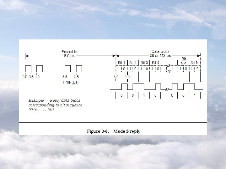
SSR Mode S ES Main characteristics (1) • On 1090 MHz channel – Secondary Surveillance radar (SSR) Mode A and C – Aircraft SSR Mode S responses to interrogations from ground-based radars • Aircraft answers to ACAS interrogations including transmission of non-solicited answers • ADS-B SSR Mode S Extended Squitters • Based on (except Modes A and C) – Multiple Access: pseudo random timing of the transmissions – Pulses modulated at 1 MHz able to convey 56 or 112 -bit messages – Downlink and Uplink predefined formats
SSR Mode S ES Main characteristics (2) • Squitters – Aircraft broadcast non-solicited long squitters (112 bits) – Data to be transmit are prepared in « registers » – Different types of SSR Mode S Extended Squitters • Airborne/Surface Position Squitter Content of registers 05/06 (rate: 0. 5 s) • Airborne Velocity Squitter: register 09 rate: 0. 5 s Aircraft Identification Squitter: register 08 • Event-Driven Squitter: register 0 A => Several Squitters are necessary to transmit data
SSR Mode S ES Standardisation status • ICAO SARPS: Annex 10 Vol III Ch 5 and Vol 4 – The current standard is Amdt 77 – Plans to modify the content of some registers in order to improve the characterisation of the safety level • RTCA MOPS – DO-260: Minimum Operational Performance Standards for 1090 MHz ADS-B – DO-260 A: with proposed improvements on safety level characterisation
SSR Mode S ES Transmitters • On-board current Transponders – Mode S transponders transmit on 1090 MHz aircraft SSR Mode S responses to interrogations from groundbased radars – They are installed on most aircraft (mandatory on all IFR aircraft in Europe as of 31/03/2005) • Evolution towards ADS-B Out Transmitters – Transmission of Extended Squitters is part of the standard (provided Registers are loaded by the avionics)
SSR Mode S ES On-board Receivers • Current TCAS – The TCAS box includes a 1090 MHz reception function of • answers of surrounding aircraft to ACAS interrogations • short squitters • Evolution towards ADS-B receiver – SSR Mode S Extended Squitters can be received and extracted by TCAS – Independency between TCAS and SSR Mode S Extended Squitters reception is required: no common failure
VDL Mode 4 Main characteristics • Frequency Band : 108 -137 MHz (i. e. Nav and Comm bands) • Bandwidth : 25 KHz per channel • Time Division Multiple Access, self organised by the mean of a common clock available to all users : UTC time (GPS) VDL 4 user terminal checks available slots and make reservations in subsequent frames for transmission • The VDL Mode 4 protocol allows to manage several VHF channels – 2 Global Signalling Channels (GSC) – Regional and Local Signalling Channels (LSC) for additional services as required • 4500 slots/minute • Bit rate : 19, 200 bits/s
VDL Mode 4 Standardisation Status • ICAO SARPS: Annex 10 Vol III Ch 6. 9 + Manual on VHF Digital Link (VDL) Mode 4 • Airborne MOPS: ED-108 A in preparation • Ground: on-going ETSI standardisation
UAT Main characteristics • Designed specifically for ADS-B with no constraints from legacy systems • Single common wideband channel 2 -3 MHz 1 Mbps channel rate in 960 -1215 MHz (ARNS band) • Aircraft access the channel autonomously at random • Transmission rate: 1/sec.
UAT Status • Standardisation status – Frequency allocation: need to be co-ordinated on a world-wide basis – SARPs not yet available – MOPS available (DO-282) • Product status – UAT part of Safe. Flight-21 Link Evaluation study – UAT selected by FAA Alaska Region (100 -200 installations in Western Alaska)
TIS-B Definition • TIS-B « A service provided by ground stations, broadcasting information relating to aircraft based on surveillance carried out by ground systems, using ADS-B signals, formats and protocols, compatible with ADS-B receiving equipment » (Draft ICAO ASAS Circular) • Data link technologies identical to ADS-B • Depends on a ground surveillance infrastructure – e. g. SSR, PSR, ADS-B, multilateration, ASDE • Users: surrounding Aircraft/Vehicle
TIS-B Role & Status • Role – Provides aircraft with a complete picture of the traffic – Exact role to be defined (ADS-B gap filler, ADS-B data validation, Bridge between different ADS-B data link technologies, Primary source for some ASAS applications? ) • Status – Elements in ICAO SARPS for SSR Mode S Extended Squitters and VDL Mode 4 technologies – Complete SARPS to be developed – RTCA MASPS DO-280
On-board Sensors • ADS-B requires on-board availability of – Aircraft position • May be based on GPS or FMS multisensor position • Available on all RNAV capable aircraft • Integrity data from GPS (more difficult with FMS) – Altitude and related data – Barometric altitude: always available – Geometric altitude: if GPS – Status • Ident: ICAO address and Call sign may require specific Control Panel
Active Interrog Data Link layer Surveillance layer Applications layer ACAS Logic tracks TA/RA ACAS Surveillance Active reply 1090 MHz Receiver UAT / VDL M 4 Receivers On-board Processing ASAS tracks ADS-B TIS-B Surveillance Data Processing Own position Display Management Display ASAS tracks, Selected target, Guidance data ASAS Applications Other Systems (FMS, MCDU…)
On-board Display • Cockpit Display of Traffic Information (CDTI) – Example of Navigation (FMS), TCAS and ASAS sharing the same display