Lecture 7 1 To determine the displacement of
 To determine the displacement of 2) axially loaded member. 2)")


- Slides: 16
Lecture - 7 1) To determine the displacement of 2) axially loaded member. 2) To find internal forces using 3) compatibility equations. 3) To determine stress within axially 4) loaded members.
The Shear Stress-Strain Diagram G
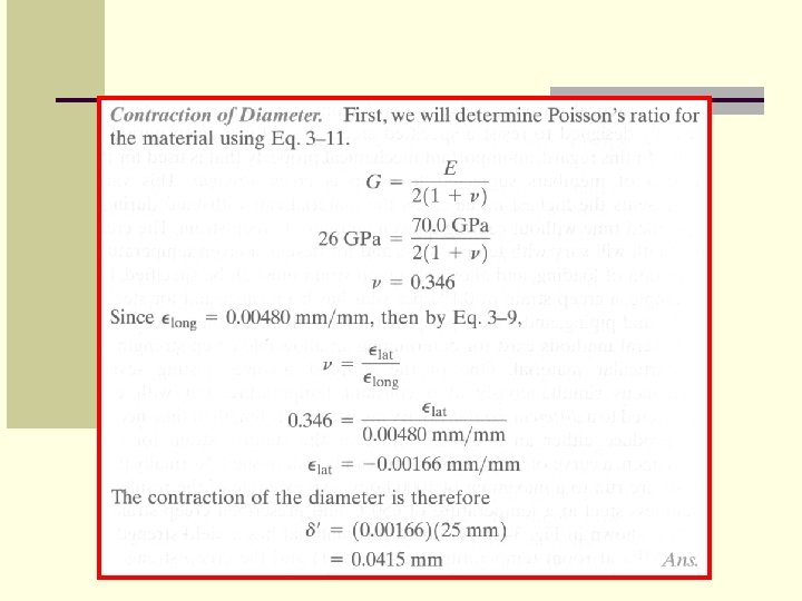
Example: An aluminum specimen shown in figure has a diameter of d 0 = 25 mm and a gauge length of L 0 = 250 mm. If a force of 165 k. N elongates the gauge length of 1. 20 mm, determine the modulus of elasticity. Also, determine by how much the force causes the diameter of the specimen to contact. Take Gal = 26 GPa and = 440 MPa.
Solution:
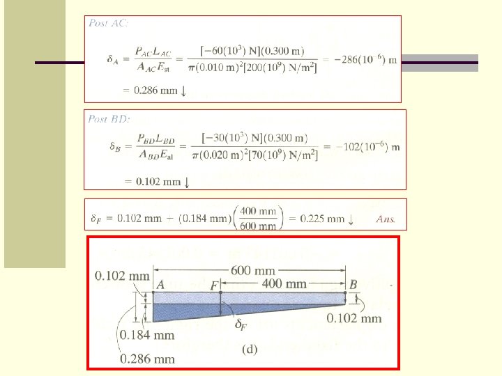
Example: A rigid beam AB rests on the two short posts as shown in figure, AC is made of steel and has a diameter of 20 mm, and BD is made of aluminum and has a diameter of 40 mm. Determine the displacement of point F on AB if a vertical load of 90 k. N is applied over this point. Take Est = 200 GPa, Eal = 70 GPa.
Solution:
Statically Indeterminate Axially Loaded Member FB + F A – P = 0 A/B = 0
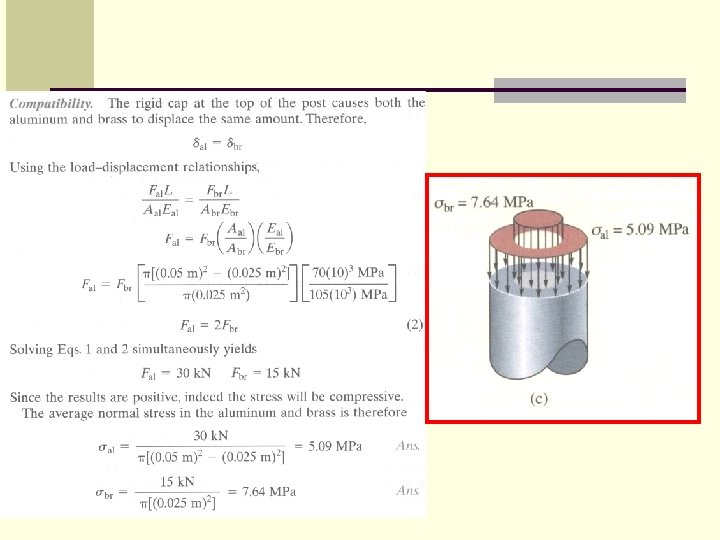
Example: The aluminum post as shown in figure is reinforced with a brass core. If this assembly supports a resultant axial compressive load of P = 45 k. N, applied to the rigid cap, determine the average normal stress in the aluminum and the brass. Take Eal = 70 (103) MPa and Ebr = 105 (103) MPa.
Solution: Equilibrium. - 45 k. N + Fal + Fbr = 0
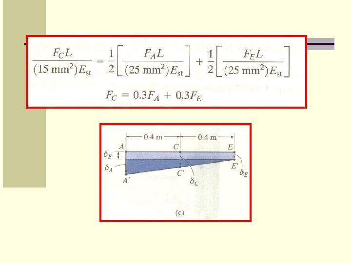
Example: The three A-36 steel bars as shown in figure are pin connected to a rigid member. If the applied load on the member is 15 k. N, determine the force developed in each bar. Bars AB and EF each have a crosssectional area of 25 mm 2, and bar CD has a cross-sectional area of 15 mm 2.
Solution: