
Lecture 5 Transmission Hui Zhang Department of Computer
- Slides: 30
Lecture 5 Transmission Hui Zhang Department of Computer Science Carnegie Mellon University http: //www. cs. cmu. edu/~srini/15 -441/F 07 1
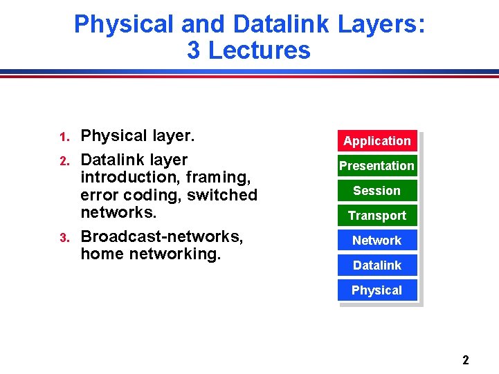
Physical and Datalink Layers: 3 Lectures 1. 2. 3. Physical layer. Datalink layer introduction, framing, error coding, switched networks. Broadcast-networks, home networking. Application Presentation Session Transport Network Datalink Physical 2
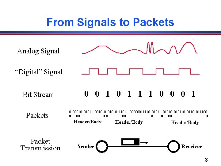
From Signals to Packets Analog Signal “Digital” Signal Bit Stream Packets Packet Transmission 0 0 1 1 1 0 0 0 1 01000101110010101110111000000111101010101011010111001 Header/Body Sender Header/Body Receiver 3
Today’s Lecture l l l l Modulation. Bandwidth limitations. Frequency spectrum and its use. Multiplexing. Media: Copper, Fiber, Optical, Wireless. Coding. Framing. 4
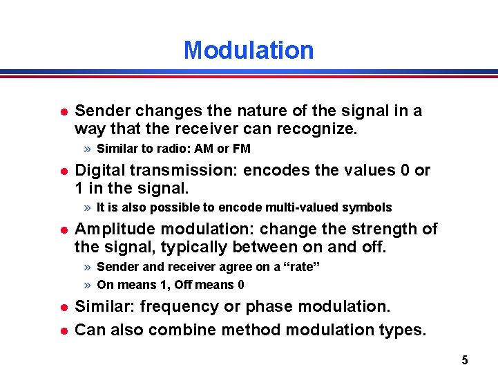
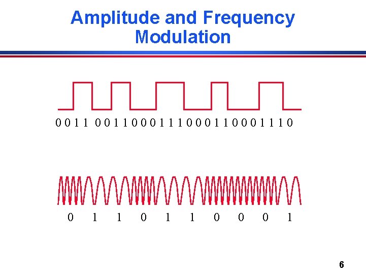
Modulation l Sender changes the nature of the signal in a way that the receiver can recognize. » Similar to radio: AM or FM l Digital transmission: encodes the values 0 or 1 in the signal. » It is also possible to encode multi-valued symbols l Amplitude modulation: change the strength of the signal, typically between on and off. » Sender and receiver agree on a “rate” » On means 1, Off means 0 l l Similar: frequency or phase modulation. Can also combine method modulation types. 5
Amplitude and Frequency Modulation 00110001110001110 0 1 1 0 0 0 1 6
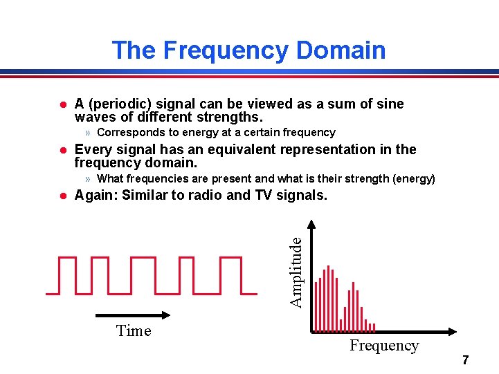
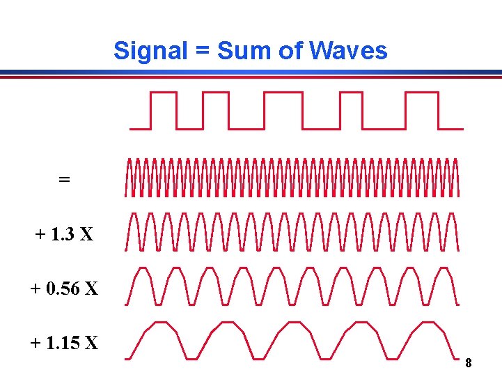
The Frequency Domain l A (periodic) signal can be viewed as a sum of sine waves of different strengths. » Corresponds to energy at a certain frequency l Every signal has an equivalent representation in the frequency domain. » What frequencies are present and what is their strength (energy) Again: Similar to radio and TV signals. Amplitude l Time Frequency 7
Signal = Sum of Waves = + 1. 3 X + 0. 56 X + 1. 15 X 8
Why Do We Care? l l l How much bandwidth can I get out of a specific wire (transmission medium)? What limits the physical size of the network? How can multiple hosts communicate over the same wire at the same time? How can I manage bandwidth on a transmission medium? How do the properties of copper, fiber, and wireless compare? 9
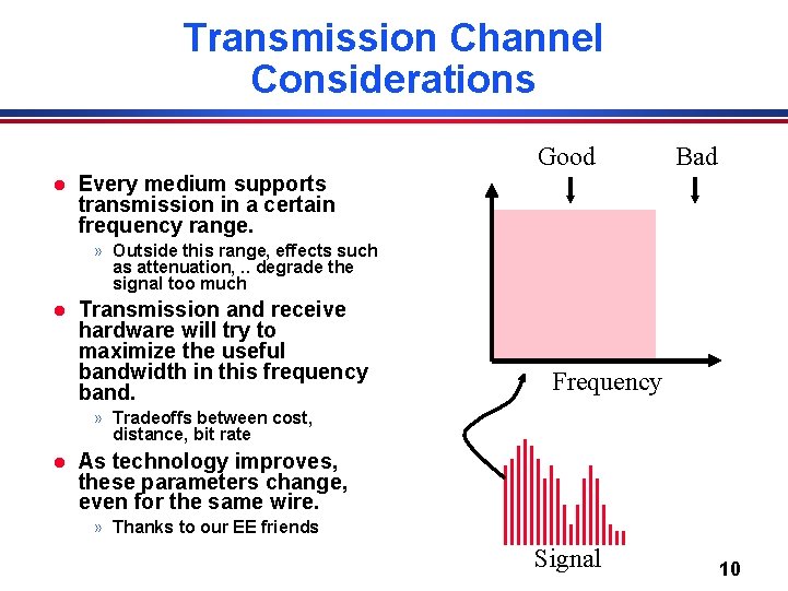
Transmission Channel Considerations Good l Bad Every medium supports transmission in a certain frequency range. » Outside this range, effects such as attenuation, . . degrade the signal too much l Transmission and receive hardware will try to maximize the useful bandwidth in this frequency band. Frequency » Tradeoffs between cost, distance, bit rate l As technology improves, these parameters change, even for the same wire. » Thanks to our EE friends Signal 10
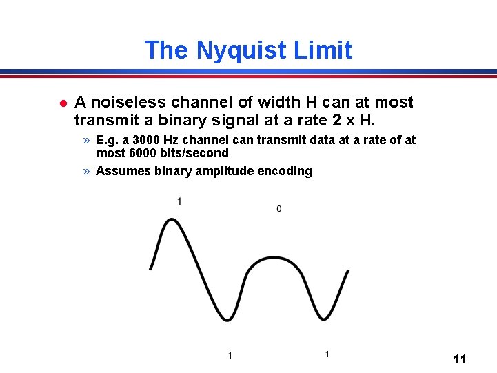
The Nyquist Limit l A noiseless channel of width H can at most transmit a binary signal at a rate 2 x H. » E. g. a 3000 Hz channel can transmit data at a rate of at most 6000 bits/second » Assumes binary amplitude encoding 11
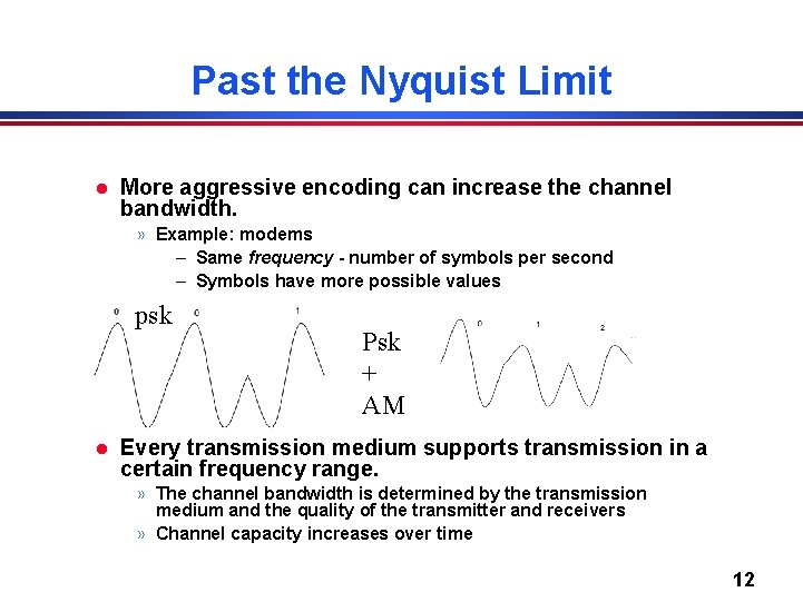
Past the Nyquist Limit l More aggressive encoding can increase the channel bandwidth. » Example: modems – Same frequency - number of symbols per second – Symbols have more possible values psk l Psk + AM Every transmission medium supports transmission in a certain frequency range. » The channel bandwidth is determined by the transmission medium and the quality of the transmitter and receivers » Channel capacity increases over time 12
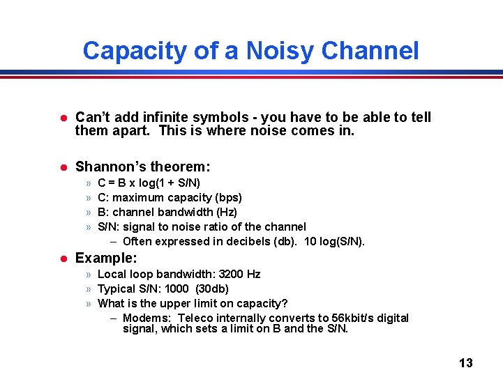
Capacity of a Noisy Channel l Can’t add infinite symbols - you have to be able to tell them apart. This is where noise comes in. l Shannon’s theorem: » » l C = B x log(1 + S/N) C: maximum capacity (bps) B: channel bandwidth (Hz) S/N: signal to noise ratio of the channel – Often expressed in decibels (db). 10 log(S/N). Example: » Local loop bandwidth: 3200 Hz » Typical S/N: 1000 (30 db) » What is the upper limit on capacity? – Modems: Teleco internally converts to 56 kbit/s digital signal, which sets a limit on B and the S/N. 13
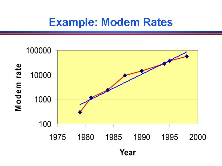
Example: Modem Rates 14
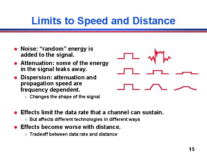
Limits to Speed and Distance l l l Noise: “random” energy is added to the signal. Attenuation: some of the energy in the signal leaks away. Dispersion: attenuation and propagation speed are frequency dependent. » Changes the shape of the signal l Effects limit the data rate that a channel can sustain. » But affects different technologies in different ways l Effects become worse with distance. » Tradeoff between data rate and distance 15
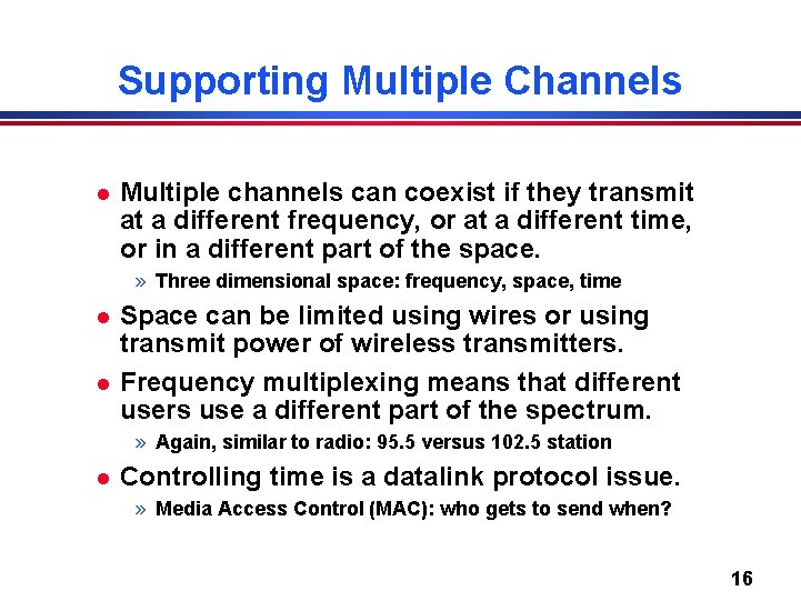
Supporting Multiple Channels l Multiple channels can coexist if they transmit at a different frequency, or at a different time, or in a different part of the space. » Three dimensional space: frequency, space, time l l Space can be limited using wires or using transmit power of wireless transmitters. Frequency multiplexing means that different users use a different part of the spectrum. » Again, similar to radio: 95. 5 versus 102. 5 station l Controlling time is a datalink protocol issue. » Media Access Control (MAC): who gets to send when? 16
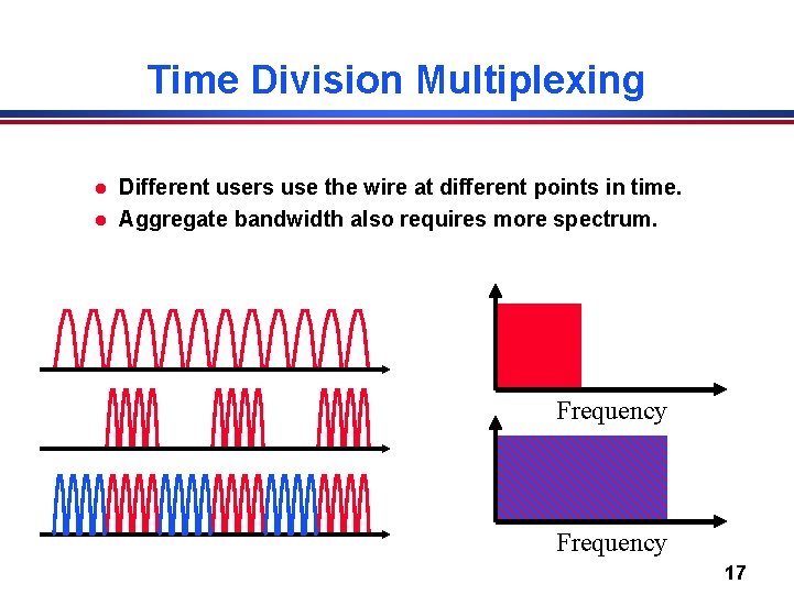
Time Division Multiplexing l l Different users use the wire at different points in time. Aggregate bandwidth also requires more spectrum. Frequency 17
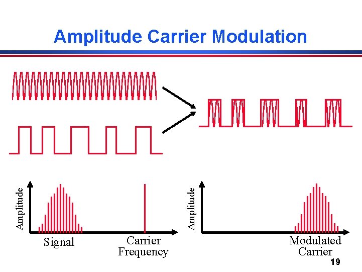
Baseband versus Carrier Modulation l l Baseband modulation: send the “bare” signal. Carrier modulation: use the signal to modulate a higher frequency signal (carrier). » Can be viewed as the product of the two signals » Corresponds to a shift in the frequency domain l Same idea applies to frequency and phase modulation. » E. g. change frequency of the carrier instead of its amplitude 18
Amplitude Carrier Modulation Signal Carrier Frequency Modulated Carrier 19
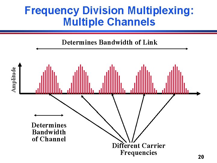
Frequency Division Multiplexing: Multiple Channels Amplitude Determines Bandwidth of Link Determines Bandwidth of Channel Different Carrier Frequencies 20
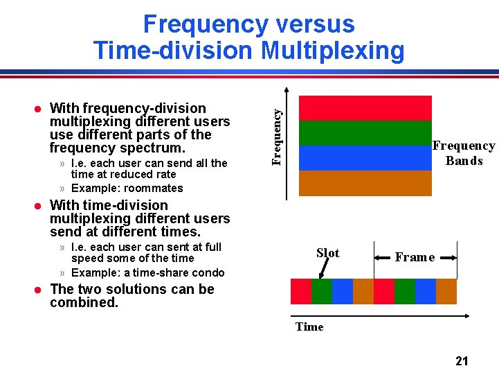
l With frequency-division multiplexing different users use different parts of the frequency spectrum. » I. e. each user can send all the time at reduced rate » Example: roommates l Frequency Bands With time-division multiplexing different users send at different times. » I. e. each user can sent at full speed some of the time » Example: a time-share condo l Frequency versus Time-division Multiplexing Slot Frame The two solutions can be combined. Time 21
Copper Wire l Unshielded twisted pair » » » l Two copper wires twisted - avoid antenna effect Grouped into cables: multiple pairs with common sheath Category 3 (voice grade) versus category 5 100 Mbit/s up to 100 m, 1 Mbit/s up to a few km Cost: ~ 10 cents/foot Coax cables. » One connector is placed inside the other connector » Holds the signal in place and keeps out noise » Gigabit up to a km l Signaling processing research pushes the capabilities of a specific technology. » E. g. modems, use of cat 5 22
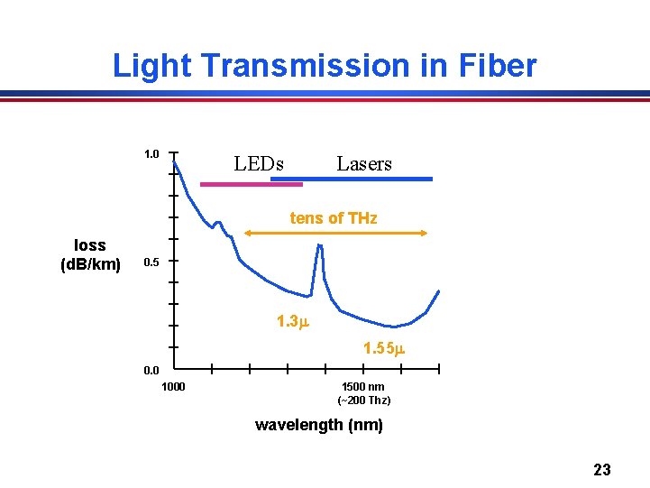
Light Transmission in Fiber 1. 0 LEDs Lasers tens of THz loss (d. B/km) 0. 5 1. 3 1. 55 0. 0 1000 1500 nm (~200 Thz) wavelength (nm) 23
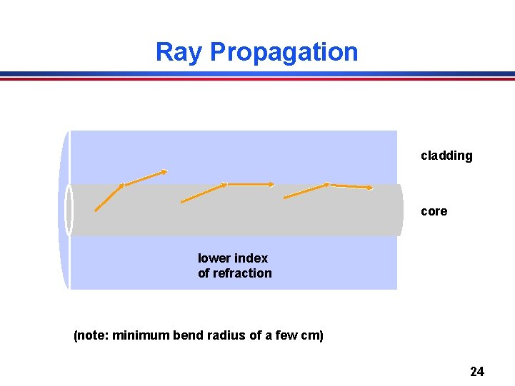
Ray Propagation cladding core lower index of refraction (note: minimum bend radius of a few cm) 24
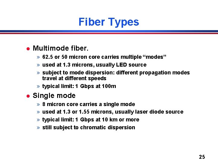
Fiber Types l Multimode fiber. » 62. 5 or 50 micron core carries multiple “modes” » used at 1. 3 microns, usually LED source » subject to mode dispersion: different propagation modes travel at different speeds » typical limit: 1 Gbps at 100 m l Single mode » » 8 micron core carries a single mode used at 1. 3 or 1. 55 microns, usually laser diode source typical limit: 1 Gbps at 10 km or more still subject to chromatic dispersion 25
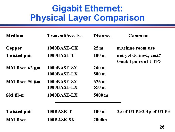
Gigabit Ethernet: Physical Layer Comparison Medium Transmit/receive Distance Comment Copper 1000 BASE-CX 25 m machine room use Twisted pair 1000 BASE-T 100 m not yet defined; cost? Goal: 4 pairs of UTP 5 MM fiber 62 m 1000 BASE-SX 1000 BASE-LX 260 m 500 m MM fiber 50 m 1000 BASE-SX 1000 BASE-LX 525 m 550 m SM fiber 1000 BASE-LX 5000 m Twisted pair 100 BASE-T 100 m MM fiber 100 BASE-SX 2000 m 2 p of UTP 5/2 -4 p of UTP 3 26
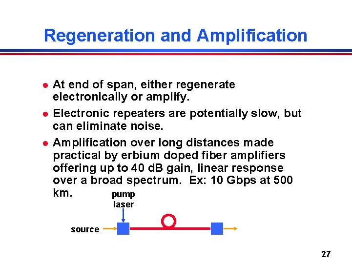
Regeneration and Amplification l l l At end of span, either regenerate electronically or amplify. Electronic repeaters are potentially slow, but can eliminate noise. Amplification over long distances made practical by erbium doped fiber amplifiers offering up to 40 d. B gain, linear response over a broad spectrum. Ex: 10 Gbps at 500 km. pump laser source 27
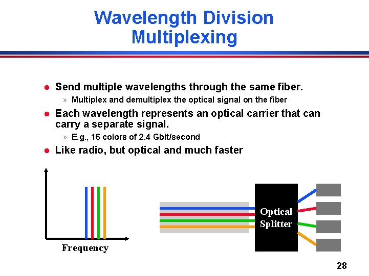
Wavelength Division Multiplexing l Send multiple wavelengths through the same fiber. » Multiplex and demultiplex the optical signal on the fiber l Each wavelength represents an optical carrier that can carry a separate signal. » E. g. , 16 colors of 2. 4 Gbit/second l Like radio, but optical and much faster Optical Splitter Frequency 28
Wireless Technologies l l Great technology: no wires to install, convenient mobility, . . High attenuation limits distances. » Wave propagates out as a sphere » Signal strength reduces quickly (1/distance)3 l High noise due to interference from other transmitters. » Use MAC and other rules to limit interference » Aggressive encoding techniques to make signal less sensitive to noise l l Other effects: multipath fading, security, . . Ether has limited bandwidth. » Try to maximize its use » Government oversight to control use 29
Things to Remember l Bandwidth and distance of networks is limited by physical properties of media. » Attenuation, noise, … l Network properties are determined by transmission medium and transmit/receive hardware. » Nyquist gives a rough idea of idealized throughput » Can do much better with better encoding – Low b/w channels: Sophisticated encoding, multiple bits per wavelength. – High b/w channels: Simpler encoding (FM, PCM, etc. ), many wavelengths per bit. l l Multiple users can be supported using space, time, or frequency division multiplexing. Properties of different transmission media. 30