Lecture 5 Refrigeration Liquefaction Part 2 J G


- Slides: 21

Lecture 5 Refrigeration & Liquefaction (Part 2) J. G. Weisend II

Joule-Thomson Expansion § Isenthalpic (h=constant) expansion § Fluid cools as is it is expanded at constant enthalpy through a valve § However, depending on both the fluid and the temperature, such an expansion can also cause heating. § Define the Joule-Thomson expansion coefficient § mj must be positive for cooling to occur § Cooling by JT expansion has some advantages • No moving parts • Can easily handle two-phase mixtures Slide 2

JT Inversion Curve & Maximum Inversion Temperatures Fluid Max Inversion Temperature (K) Nitrogen 623 Argon 723 Hydrogen 202 He 43 § Maximum inversion temperature for helium is 43 K § Note that below ~ 2 K He again warms on JT expansion Inversion curve for Helium § Many fluids, such as N 2 can be liquefied using JT expansion – JT cycle Slide 3

Joule-Thomson Refrigerator § Simple From Cryogenic Systems R. Barron § Mainly used for cryocoolers (more later) and not for large plants § Also known as a Linde-Hampson Refrigerator Slide 4

Practical Large Scale Helium Refrigerators (at last) § Modern large scale Helium refrigerators/liquefiers use a variation of the Claude cycle known as the Collins cycle § The key difference between these cycles and the JT cycle is the addition of expansion engines (pistons or turbines) that the fluid does work against and thus cools § The process through these expansion engines may be idealized as Isentropic (s = constant) expansion • Cooling occurs at any temperature • DT for a given DP is much larger than for isenthalpic expansion § Claude cycle = 1 expansion engine, Collins cycle = multiple expansion engines • The post WW II development of the Collins liquefier revolutionized laboratory research in cryogenics Slide 5

Claude Cycle From Cryogenic Systems R. Barron Slide 6

CTI 4000 Refrigerator (early 80’s vintage ~ 1. 2 k. W @ 4. 5 K) Slide 7

Accelerator Cryoplant for ESS (Linde) Note: 1) No LN 2 Precooling 2) Last stage of subatmospheric pumping is warm 3) Provides up to 3 k. W @ 2 K Slide 8

Major Components of a Helium Refrigeration Plant § Helium Screw Compressors • Operate at room temperature • Are oil flooded – compress a mixture of He gas and special oil • Require water cooling to remove heat due to compression • Vast majority of power goes here From Dunham Bush Co. ESS ACCP Compressor Slide 9

Schematic of Helium Compressor Combined control venting valve non return valve inlet valve Compressor (screws) bulk oil separator oil filter oil cooler gas cooler Courtesy Linde/Kaeser Slide 10

Major Components of a Helium Refrigeration Plant § Oil Removal Systems • Removes oil down to the ppb level – critical for properation of the plant • Bulk Oil Separators: should reduce level down to < than 250 ppm • Coalescers: two or more in series reduce oil level down to < 10 ppm • Absorbers: » contain activated charcoal » Are redundant » Reduces level down to < 1 ppb » Can be regenerated via warm N 2 gas § Cold Box • Contains cryogenic components » Heat exchangers » Valves » Expansion Turbines » Piping » Vacuum insulated Slide 11

Brazed Plate Fin Heat Exchangers § All aluminum § Vacuum brazed § Very compact § High efficiency § Can handle multiple streams § Standard for cryogenic plants From The Handbook of Cryogenic Engineering Courtesy Linde Slide 12

Expansion Turbines § One of the key technologies for cryogenic plants § Proprietary designs resulting from a significant amount of R&D § Modern ones are quite reliable § Water cooling is generally required to absorb work at room temperature § May operate at speeds up to 120, 000 rpm § Two primary suppliers: Air Liquide and Linde Slide 13

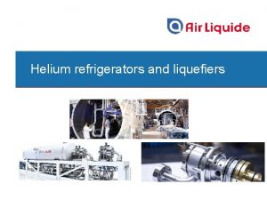
Examples of Expansion Turbines Courtesy Air Liquide Courtesy Linde Slide 14

ACCP Compressors, Heat Exchangers and Oil Removal System 15

ACCP Cold Box - Linde 16

Major Components of a Helium Refrigeration Plant § Main Distribution Box • Connects refrigeration plant with the distribution lines § Storage vessels (LN 2, LHe, GHe) § Purifier: separate system that removes impurities from the helium space of the cryogenic system, including piping and items being cooled • Contamination control is very important to reliable operation § Control System • Generally PLC based with a higher level HMI • Once fully commissioned, modern Helium refrigeration plants can operate autonomously 24/7 Slide 17

Ba. Bar Liquefier Control Screen SLAC Slide 18

Backup Slides Slide 19

Collins Cycle § Cycle consists of : 1) Compression to ~ 16 Bar with cooling back to 300 K + oil removal 2) Cooling of high pressure gas with LN 2 3) Isentropic expansion via 2 or more expansion engines 4) Cooling of high pressure gas by the cold returning low pressure stream 5) Isenthalpic expansion through JT valve 6) Return of gas to compressors at just above 1 Bar Slide 20

Expansion Turbine Bearing Options (Gas bearings are the most common now) Oil Bearing Static Gas Bearing To Compressor Turbine Dynamic Gas Bearing Oil Bearing Gas Sealing Gas Turbine To Compressor Courtesy Linde Slide 21
 01:640:244 lecture notes - lecture 15: plat, idah, farad
 Physical incompatibility with example
 Richter scale range
 Millers liquefaction foci
 Whats the main cause of most earthquakes
 Nécrose de coagulation anapath
 Maji jose
 Helium liquefaction temperature
 Snycline
 Liquefaction foci dentin
 Food preservation principle
 Fridge thanda
 Polair refrigeration
 Hvac slideshare
 What is refrigerant glide
 Cop of refrigerator
 Viroligy
 Difference between refrigerator and heat pump
 Evaporator diagram
 Standard refrigeration heat exchanger
 1 ton of refrigeration
 Magnetic refrigeration
