Lecture 5 2 Impedance Phasor Diagram IMPEDANCE AND


 curve using different hysteresis loops")

,")


- Slides: 47
Lecture 5 -2 Impedance Phasor Diagram
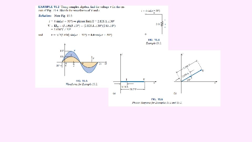
IMPEDANCE AND THE PHASOR DIAGRAM Resistive Elements
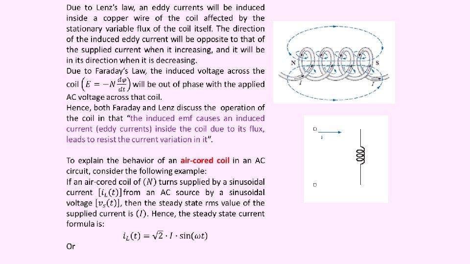
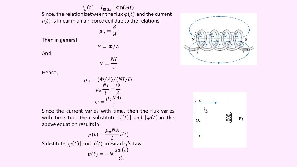
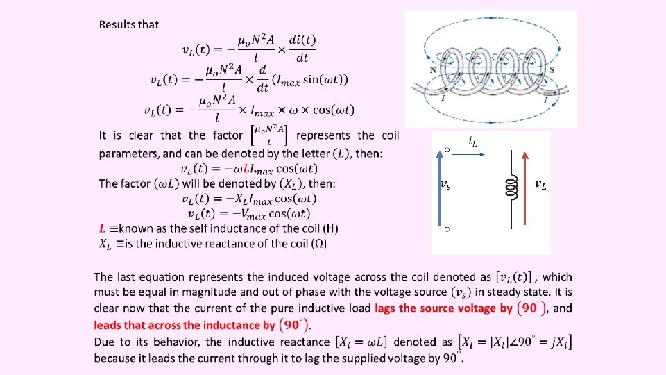
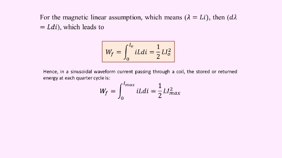
What is the Inductance? When a conducting wire wound in the manner shown in figure beside, it will be a “Coil” and it will be called “an inductor” ( ) because it behaves as “an inductance” ( ﺣﺎﻩ ). The questions arise here are: “What is this winding ( ) do? ” “What it will induce? ” “What happen when it is connected to a DC source? ” “What happen when it is connected to an AC source? ”
DC
Eddy Currents Y x z These induced currents are known as “eddy currents” ( )ﺍﻟﺘﻴﺎﺭﺍﺕ ﺍﻟﺪﻭﺍﻣﺔ. Their motion in a short circuited loops in the conducting medium are the source of a heat and considered as: “eddy current losses”.
S N The diagram and waveforms shown below, describe the behavior of the inductance during a complete cycle of current with its four periods at steady state.
1 0, 5 0 0 90 180 270 360 -0, 5 -1 Flux rate AC Source Load Power Inc. Source Load Dec. Inc. Dec. Load Source S S N N S S
From the above analysis it seems clear the power will Discussion: • This behavior of the inductance means that it will resist the flow of the current during halftime of the cycle (when it considered as a load) and it will assist him to flow during the rest of the time of the cycle (when it considered as a source). Hence, its behavior is not like that of the resistor. • The net power consumed by the inductance is zero.
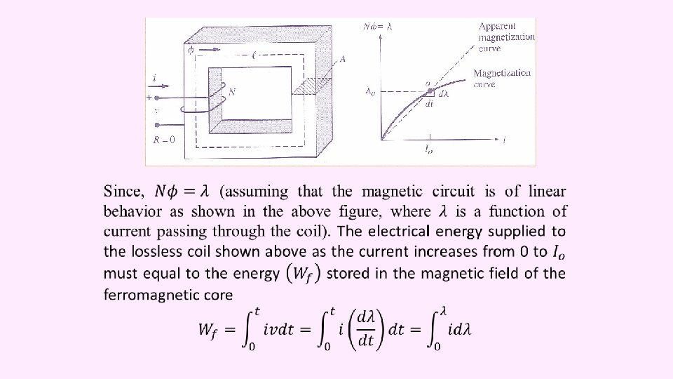
The operation of an Iron-Cored AC Fed Coil Iron Core
Moving domain walls in a grain of silicon steel caused by an increasing external magnetic field in the "downward" direction, observed in a Kerr microscope. White areas are domains with magnetization directed up, dark areas are domains with magnetization directed down.
An animation showing how magnetostriction works. A changing external magnetic field causes the magnetic dipoles to rotate, changing the dimensions of the crystal lattice. This motion leads to a heat and considered as: “Hysteresis Losses”
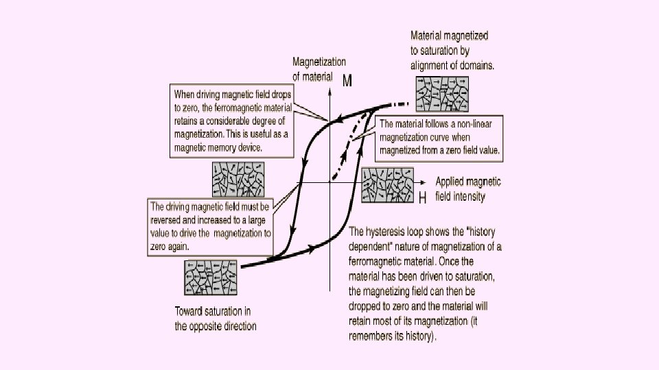
Typical Hysteresis Loop
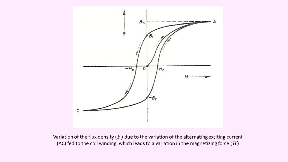
Formation of the (B-H) curve using different hysteresis loops
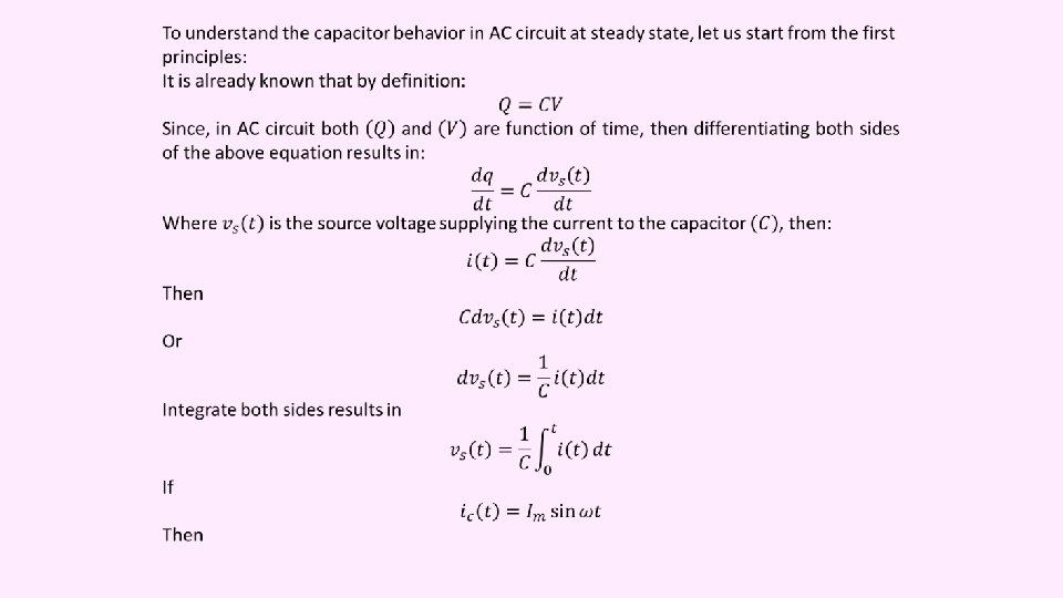
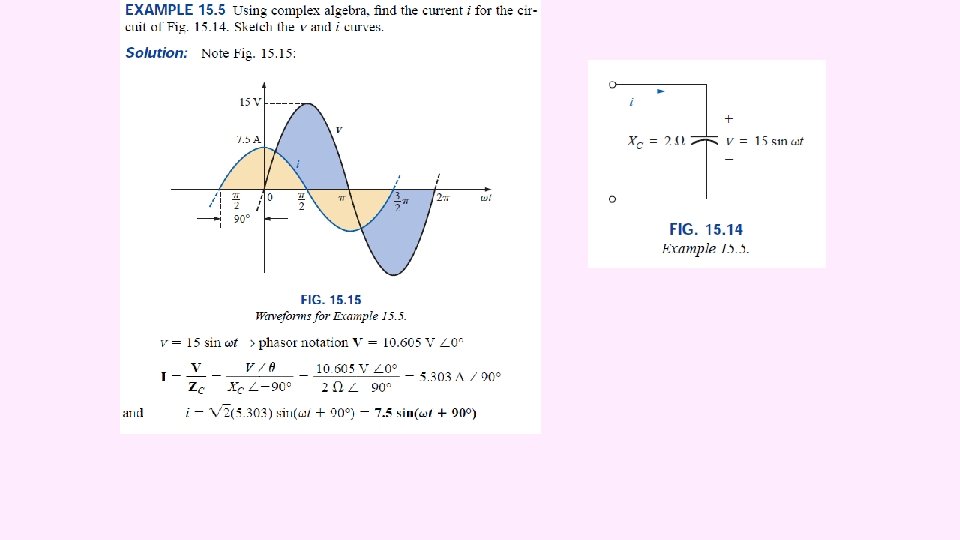
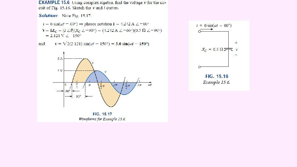
Consider the circuit shown in the figure beside, if the switch is closed (ON), then the current will flow in the capacitor in a random oscillatory behavior for a period known as a “transient state”, until it reaches a “steady state” in which its oscillation damped. The steady state operation of the capacitor in an AC circuit is of our interest in this course of steady. Switch AC source Capacitor
1, 5 1 Y-Axis 0, 5 0 0 5 10 15 20 -0, 5 -1 -1, 5 AC Source Load Capacitor Source Power Time (ms) Source Load
Behavior of the Capacitor in an AC Circuit • In DC circuit the capacitor considered as an open circuit at steady-state condition. Hence, no current will circulate in such circuit, but when it supplied by an AC voltage its behavior will be as follows:
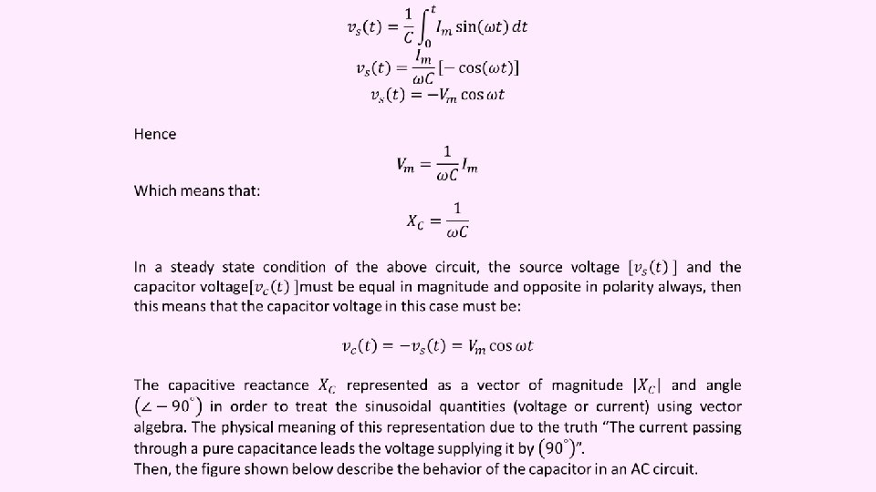
Discussion: • This behavior of the capacitance means that it will resist the flow of the current during halftime of the cycle (when it considered as a load) and it will assist him to flow during the rest of the time of the cycle (when it considered as a source). Hence, its behavior is not like that of the resistor, and it's not like that of the inductance too, in that its action as a source or as a load occurs at the inverse time periods during the cycle w. r. t. that of the inductance. • This means that the steady state current in the capacitor is flowing continuously during the AC cycle and it will never stop as the case in the DC circuit in which the capacitor is considered as an open circuit. • The net transferred power equal to zero in a pure capacitive load.
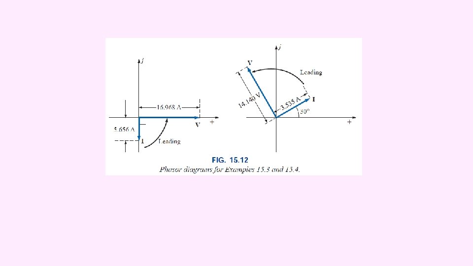
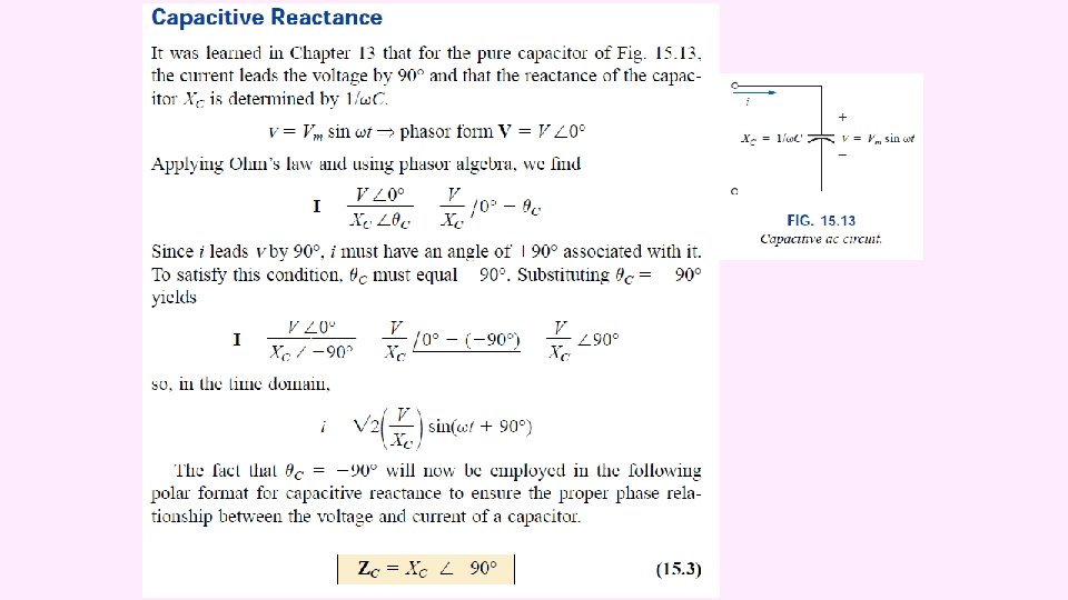
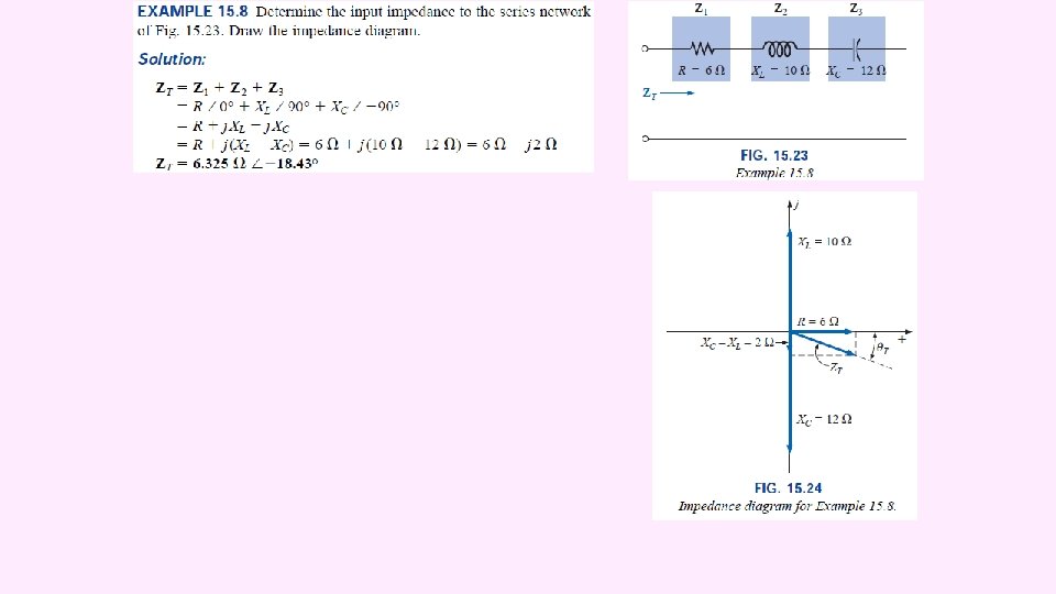
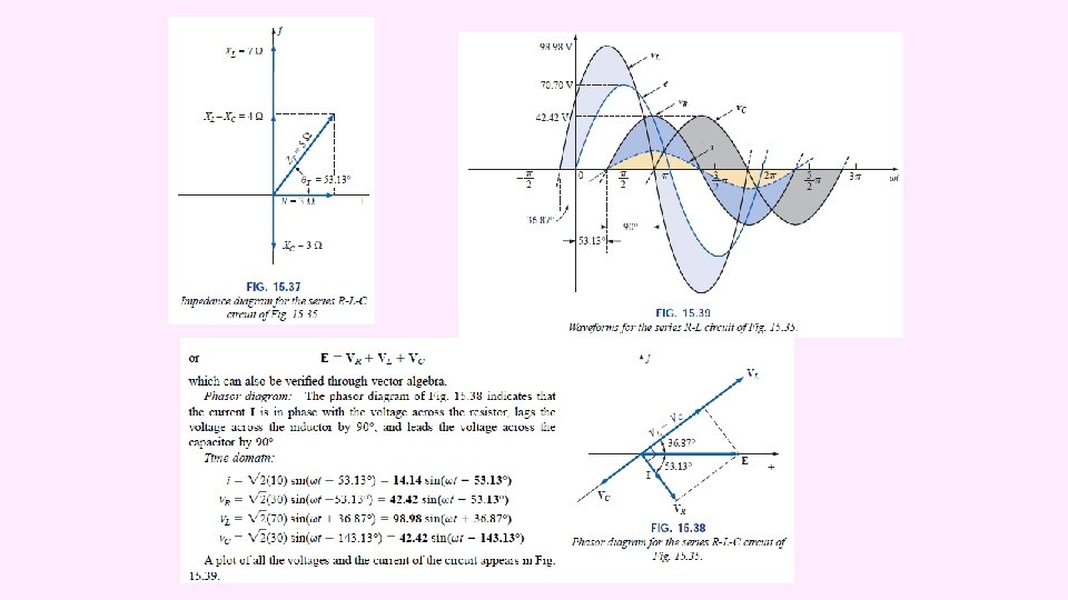
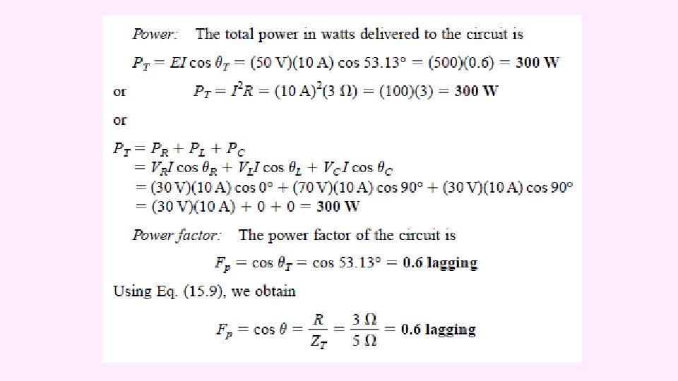
Impedance Diagram