LECTURE 4 PROJECT TIME MANAGEMENT Reference Figure 6


 § Dependency Determination § Leads and")
 • More popular than ADM method and used by project")
 • Also called activity-on-arrow (AOA) network diagrams • Activities are")
 Meaning")


")

 • Activities are represented by boxes. • Arrows show relationships")
 B Activity B (Modify Roof and")


 A Build internal components 2 B Modify")


- Slides: 46
LECTURE 4 PROJECT TIME MANAGEMENT
Reference: Figure 6. 2. PMBOK® Guide, 5 h Ed
PROJECT TIME MANAGEMENT § § § Plan Schedule Management – The process of establishing the policies, procedures, and documentation for planning, developing, managing, executing, and controlling the project schedule. Define Activities – The process of identifying and documenting the specific actions to be performed to produce the project deliverables. Sequence Activities – The process of identifying and documenting relationships among the project activities.
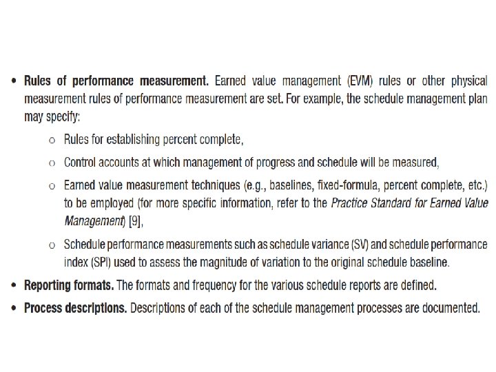
What we Have OUTPUTS Schedule Management Plan
Activity Lists and Attributes • An activity list is a tabulation of activities to be included on a project schedule. The list should include: – The activity name – An activity identifier or number – A brief description of the activity • Activity attributes provide more information about each activity, such as predecessors, successors, logical relationships, leads and lags, resource requirements, constraints, imposed dates, and assumptions related to the activity. 6
Milestones • A Milestone is a significant event that normally has no duration. • It often takes several activities and a lot of work to complete a milestone. • Milestones are useful tools for setting schedule goals and monitoring progress. • Examples include completion and customer signoff on key documents and completion of specific products • High level milestones are given in project charter
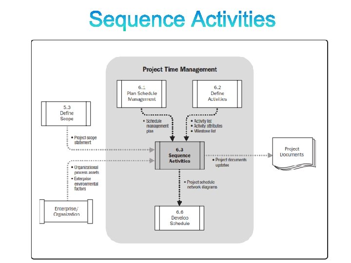
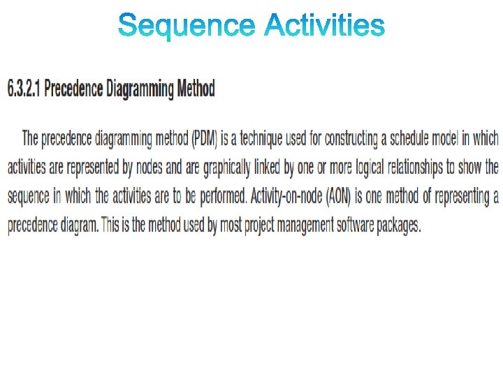
• Sequence Activities is the Process of identifying and documenting relationships among the project activities. • The key benefit of this process is that the logical sequence of work to obtain the greatest efficiency given all project constraints.
• After defining project activities, the next step is activity sequencing – Involves reviewing the activity list and attributes, project scope statement, milestone list and approved change requests to determine the relationships between activities • A dependency or relationship is the sequencing of project activities or tasks • You must determine dependencies in order to use critical path analysis 9
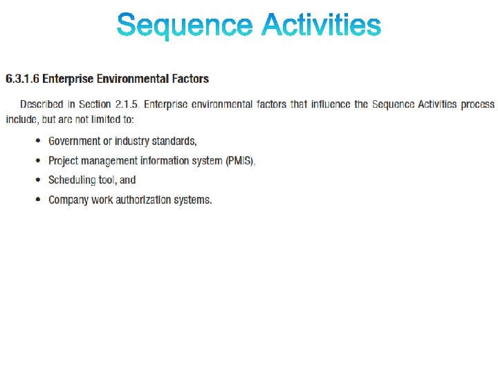
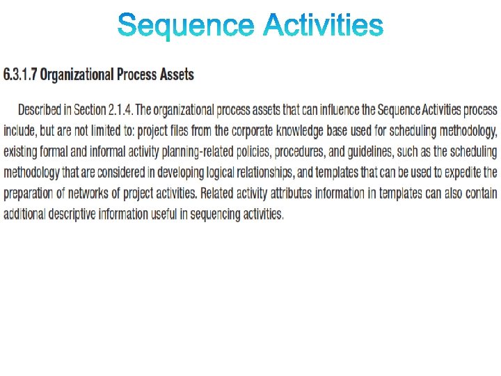
PROCESS OF IDENTIFYING AND DOCUMENTING RELATIONSHIPS AMONG THE PROJECT ACTIVITIES. 1 Inputs 1. Schedule Management Plan 2 Tools and Techniques 3 Outputs 1. Precedence Diagrammin g Method (PDM) 1. Project Schedule Network Diagrams 4. Milestone List 2. Dependency Determinatio n 2. Project Document Updates 5. Project Scope Statement 3. Leads and Lags ______ _ 6. Enterprise Environmental Factors ______ _ 2. Activity List 3. Activity Attributes
INPUTS
INPUTS
INPUTS
INPUTS
INPUTS
TOOLS & TECHNIQUES § Precedence Diagramming Method (PDM) § Dependency Determination § Leads and Lags
Precedence Diagramming Method (PDM) • More popular than ADM method and used by project management software • Activities are represented by boxes • Arrows show relationships between activities • Better at showing different types of dependencies 21
Arrow Diagramming Method (ADM) • Also called activity-on-arrow (AOA) network diagrams • Activities are represented by arrows • Nodes or circles are the starting and ending points of activities • Can only show finish-to-start dependencies • Can omit activities that have no dependencies Project Time Management 22
A Comparison of AON and AOA Network Conventions Activity on Activity Node (AON) Meaning A B C D B and C cannot begin until A is completed. D cannot begin until both B and C are completed. A dummy activity is again introduced in AOA. Activity on Arrow (AOA) A Dummy activity B D C
RELATIOSHIPS
RELATIONSHIPS Finish-to-Start – Activity A must finish before Activity B can start A B Start-to-Start – Activity A must start before Activity B can start A B
RELATIONSHIPS Finish-to-Finish – Activity A must finish before Activity B can finish A B Start-to-Finish – Activity A must start before Activity B can finish A B
Precedence Diagramming Method (PDM)
AON Example Activity A Description Build internal components Immediate Predecessors — B Modify roof and floor — C Construct collection stack A D Pour concrete and install frame A, B E Build high-temperature burner C F Install pollution control system C G Install air pollution device D, E H Inspect and test F, G Table 3. 1
Precedence Diagramming Method (PDM) • Activities are represented by boxes. • Arrows show relationships between activities. • Better at showing different types of dependencies. 29
AON Network A Activity A (Build Internal Components) B Activity B (Modify Roof and Floor) Start Activity
Activity A Precedes Activity C A C B D Start Activities A and B Precede Activity D
F A C E Start B D H G Arrows Show Precedence Relationships
TOOLS & TECHNIQUES
Three Types of Dependencies • Mandatory dependencies: inherent in the nature of the work being performed on a project, sometimes referred to as hard logic • Discretionary dependencies: defined by the project team; sometimes referred to as soft logic and should be used with care since they may limit later scheduling options – Don’t start detailed design work until users sign-off on all the analysis – good practice but can delay project • External dependencies: involve relationships between project and non-project activities – Delivery of new hardware; if delayed can impact project 34 schedule
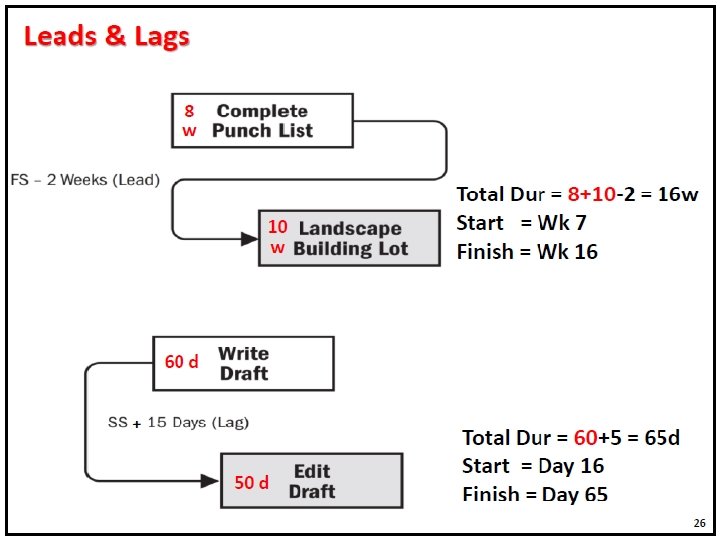
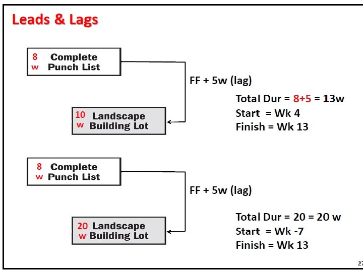
Leads and Lags
Leads and Lags
OUTPUTS § Project Schedule Network Diagram § Project Documents Updates § § Activity List Activity Attributes Milestone List Risk Register § Enterprise Environmental Factors § Organizational Process Assets
OUTPUTS
Network Diagrams • Network diagrams are the preferred technique for showing activity sequencing • A network diagram is a schematic display of the logical relationships among, or sequencing of, project activities • Two main formats are the arrow and precedence diagramming methods 41
Develop Network Diagram? Activity Description Time (weeks) A Build internal components 2 B Modify roof and floor 3 C Constructure 2 D Pour concrete and install frame 4 E Build high-temperature burner 4 F Install pollution control system 3 G Install air pollution device 5 H Inspect and test 2 Total Time (weeks) 25
Activity A Description Build internal components Immediate Predecessors — B Modify roof and floor — C Construct collection stack A D Pour concrete and install frame A, B E Build high-temperature burner C F Install pollution control system C G Install air pollution device D, E H Inspect and test F, G
OUTPUTS 6. 3. 3. 1 Project Schedule Network Diagram
OUTPUTS
Thank You