
Lecture 3 Demos capacitor separation with distance Introduce


- Slides: 94
Lecture 3 • Demos: capacitor separation with distance • Introduce dielectrics (foam, glass) and see the voltage decrease as the capacitance increases.
Electrical Sensors Employ electrical principles to detect phenomena. • May use changes in one or more of: • Electric charges, fields and potential • Capacitance • Magnetism and inductance
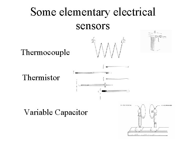
Some elementary electrical sensors Thermocouple Thermistor Variable Capacitor
Review of Electrostatics • In order to understand how we can best design electrical sensors, we need to understand the physics behind their operation. • The essential physical property measured by electrical sensors is the electric field.
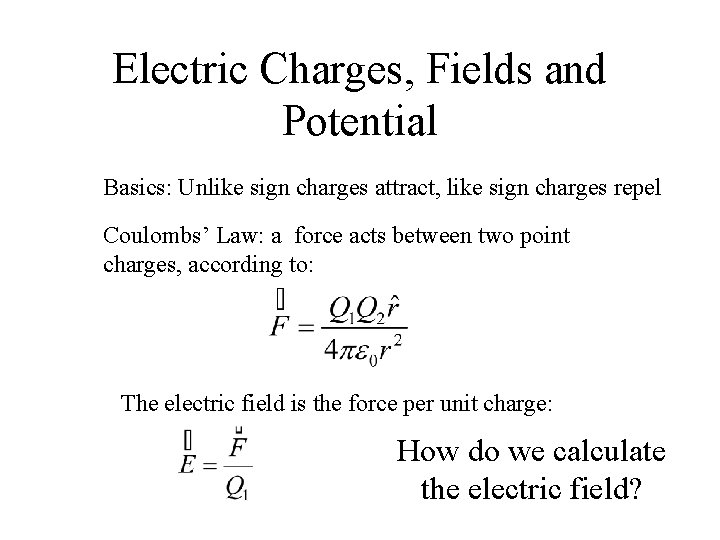
Electric Charges, Fields and Potential Basics: Unlike sign charges attract, like sign charges repel Coulombs’ Law: a force acts between two point charges, according to: The electric field is the force per unit charge: How do we calculate the electric field?
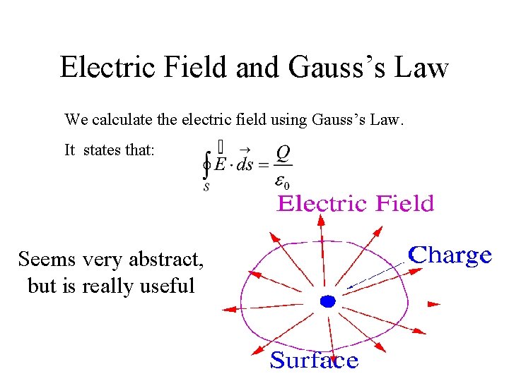
Electric Field and Gauss’s Law We calculate the electric field using Gauss’s Law. It states that: Seems very abstract, but is really useful
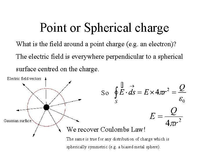
Point or Spherical charge What is the field around a point charge (e. g. an electron)? The electric field is everywhere perpendicular to a spherical surface centred on the charge. Electric field vectors So Gaussian surface We recover Coulombs Law! The same is true for any distribution of charge which is spherically symmetric (e. g. a biased metal sphere).
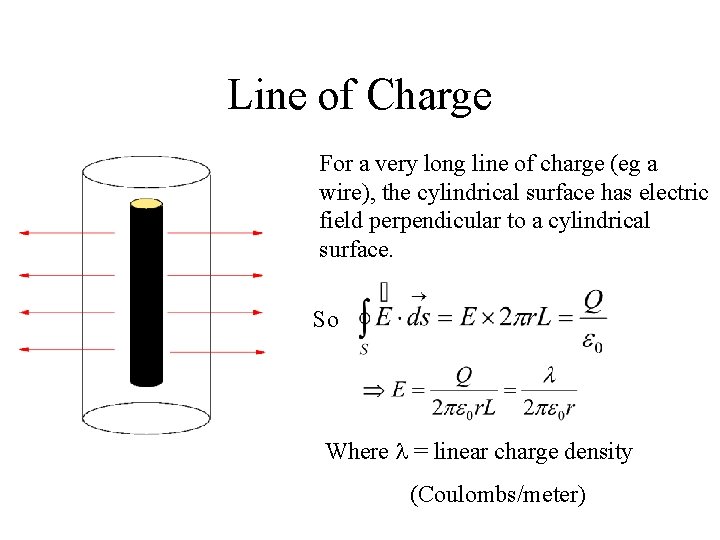
Line of Charge For a very long line of charge (eg a wire), the cylindrical surface has electric field perpendicular to a cylindrical surface. So Where = linear charge density (Coulombs/meter)
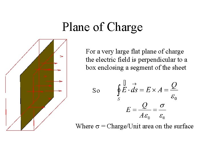
Plane of Charge For a very large flat plane of charge the electric field is perpendicular to a box enclosing a segment of the sheet So Where = Charge/Unit area on the surface
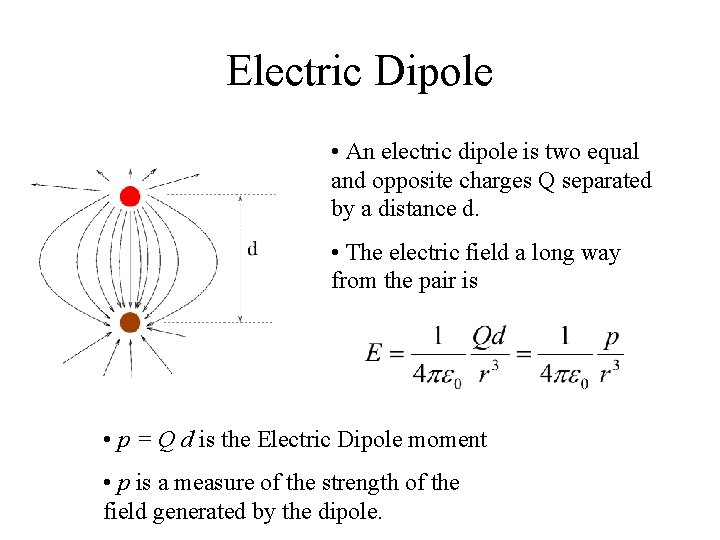
Electric Dipole • An electric dipole is two equal and opposite charges Q separated by a distance d. • The electric field a long way from the pair is • p = Q d is the Electric Dipole moment • p is a measure of the strength of the field generated by the dipole.
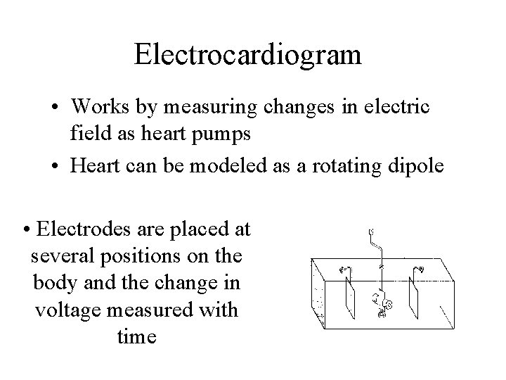
Electrocardiogram • Works by measuring changes in electric field as heart pumps • Heart can be modeled as a rotating dipole • Electrodes are placed at several positions on the body and the change in voltage measured with time
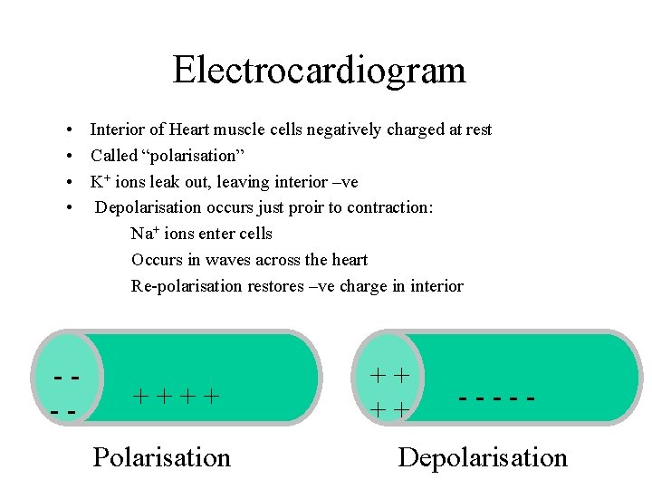
Electrocardiogram • Interior of Heart muscle cells negatively charged at rest • Called “polarisation” • K+ ions leak out, leaving interior –ve • Depolarisation occurs just proir to contraction: Na+ ions enter cells Occurs in waves across the heart Re-polarisation restores –ve charge in interior --- ++++ Polarisation ++ ++ ----- Depolarisation
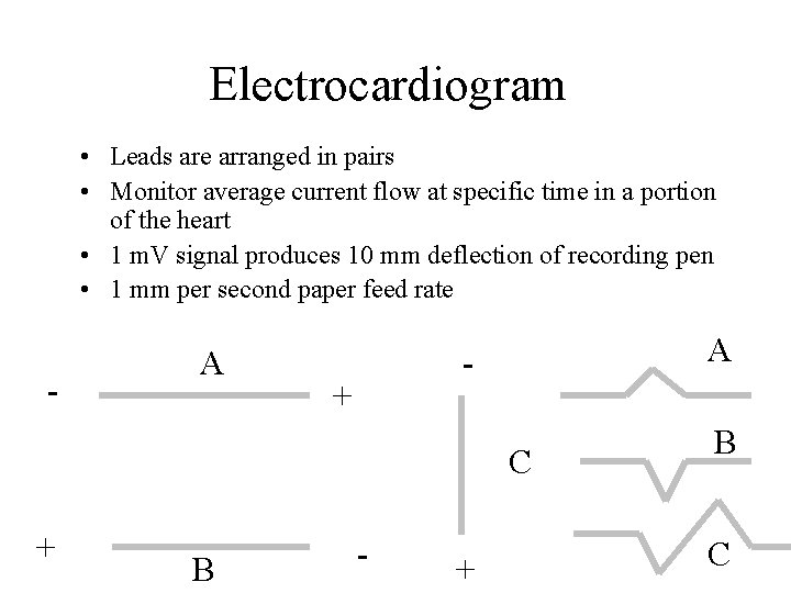
Electrocardiogram • Leads are arranged in pairs • Monitor average current flow at specific time in a portion of the heart • 1 m. V signal produces 10 mm deflection of recording pen • 1 mm per second paper feed rate - A A - + C + B - + B C
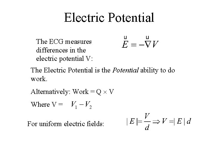
Electric Potential The ECG measures differences in the electric potential V: The Electric Potential is the Potential ability to do work. Alternatively: Work = Q V Where V = For uniform electric fields:
Electric fields on conductors. • Conductors in static electric fields are at uniform electric potential. • This includes wires, car bodies, etc. • The electric field inside a solid conductor is zero.
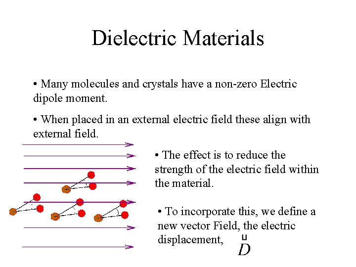
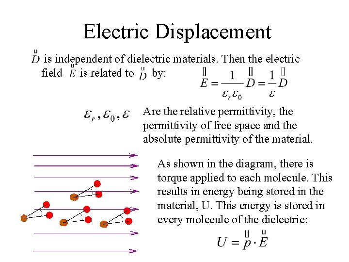
Dielectric Materials • Many molecules and crystals have a non-zero Electric dipole moment. • When placed in an external electric field these align with external field. • The effect is to reduce the strength of the electric field within the material. • To incorporate this, we define a new vector Field, the electric displacement,
Electric Displacement is independent of dielectric materials. Then the electric field is related to by: Are the relative permittivity, the permittivity of free space and the absolute permittivity of the material. As shown in the diagram, there is torque applied to each molecule. This results in energy being stored in the material, U. This energy is stored in every molecule of the dielectric:
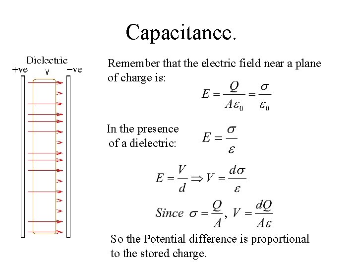
Capacitance. Remember that the electric field near a plane of charge is: In the presence of a dielectric: So the Potential difference is proportional to the stored charge.
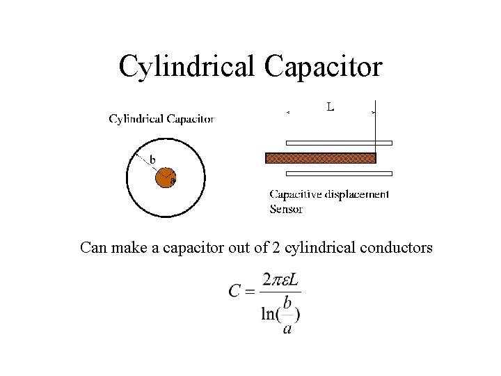
Cylindrical Capacitor Can make a capacitor out of 2 cylindrical conductors
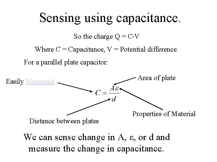
Sensing using capacitance. So the charge Q = C V Where C = Capacitance, V = Potential difference. For a parallel plate capacitor: Easily Measured Distance between plates Area of plate Properties of Material We can sense change in A, ε, or d and measure the change in capacitance.
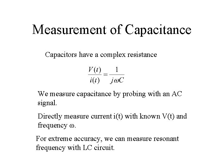
Measurement of Capacitance Capacitors have a complex resistance We measure capacitance by probing with an AC signal. Directly measure current i(t) with known V(t) and frequency ω. For extreme accuracy, we can measure resonant frequency with LC circuit.
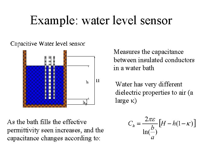
Example: water level sensor Measures the capacitance between insulated conductors in a water bath Water has very different dielectric properties to air (a large ) As the bath fills the effective permittivity seen increases, and the capacitance changes according to:
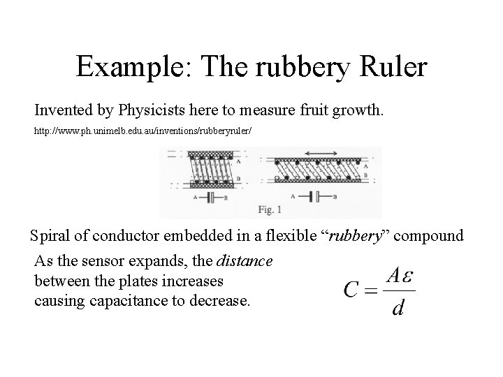
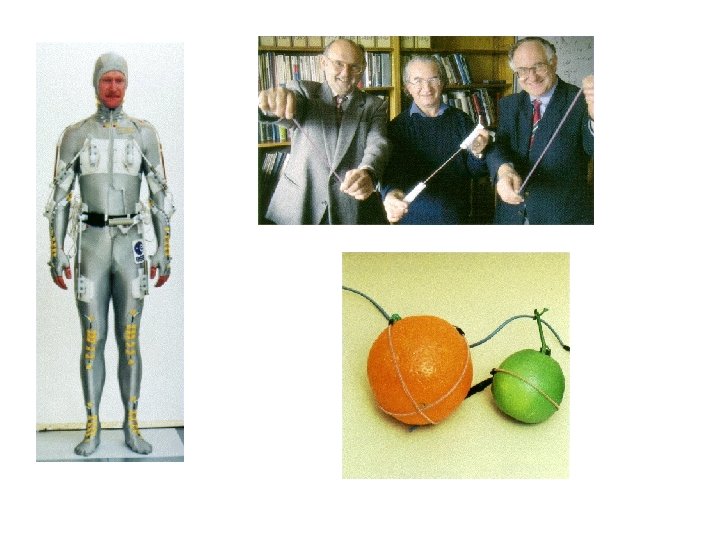
Example: The rubbery Ruler Invented by Physicists here to measure fruit growth. http: //www. ph. unimelb. edu. au/inventions/rubberyruler/ Spiral of conductor embedded in a flexible “rubbery” compound As the sensor expands, the distance between the plates increases causing capacitance to decrease.
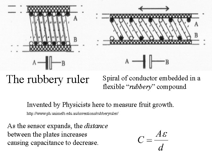
The rubbery ruler Spiral of conductor embedded in a flexible “rubbery” compound Invented by Physicists here to measure fruit growth. http: //www. ph. unimelb. edu. au/inventions/rubberyruler/ As the sensor expands, the distance between the plates increases causing capacitance to decrease.
Lecture 4 • Piezoelectric demo (stove lighter and voltmeter)
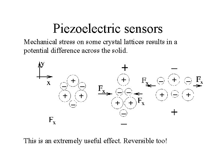
Piezoelectric sensors Mechanical stress on some crystal lattices results in a potential difference across the solid. This is an extremely useful effect. Reversible too!
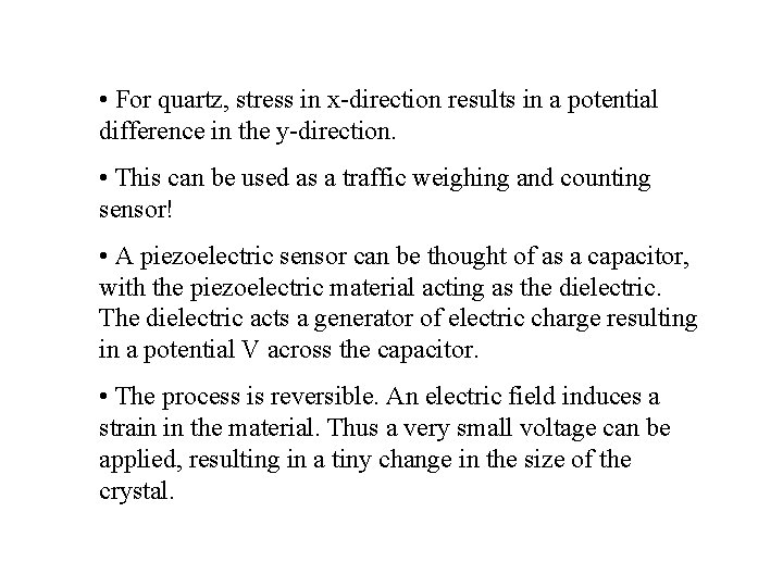
• For quartz, stress in x-direction results in a potential difference in the y-direction. • This can be used as a traffic weighing and counting sensor! • A piezoelectric sensor can be thought of as a capacitor, with the piezoelectric material acting as the dielectric. The dielectric acts a generator of electric charge resulting in a potential V across the capacitor. • The process is reversible. An electric field induces a strain in the material. Thus a very small voltage can be applied, resulting in a tiny change in the size of the crystal.
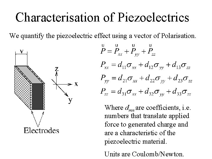
Characterisation of Piezoelectrics We quantify the piezoelectric effect using a vector of Polarisation. Where dmn are coefficients, i. e. numbers that translate applied force to generated charge and are a characteristic of the piezoelectric material. Units are Coulomb/Newton.
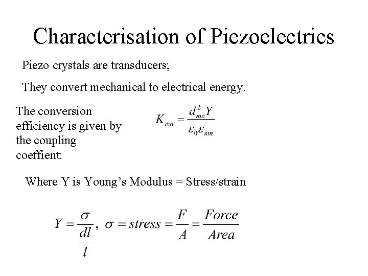
Characterisation of Piezoelectrics Piezo crystals are transducers; They convert mechanical to electrical energy. The conversion efficiency is given by the coupling coeffient: Where Y is Young’s Modulus = Stress/strain
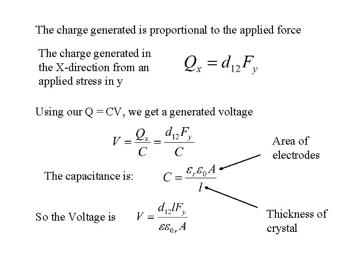
The charge generated is proportional to the applied force The charge generated in the X-direction from an applied stress in y Using our Q = CV, we get a generated voltage Area of electrodes The capacitance is: So the Voltage is Thickness of crystal
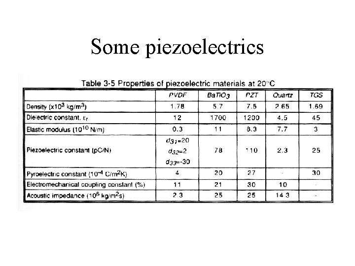
Some piezoelectrics
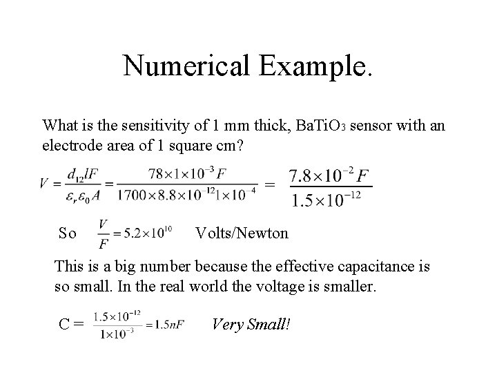
Numerical Example. What is the sensitivity of 1 mm thick, Ba. Ti. O 3 sensor with an electrode area of 1 square cm? = So Volts/Newton This is a big number because the effective capacitance is so small. In the real world the voltage is smaller. C= Very Small!
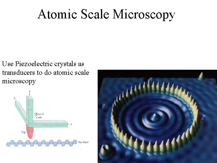
Atomic Scale Microscopy Use Piezoelectric crystals as transducers to do atomic scale microscopy
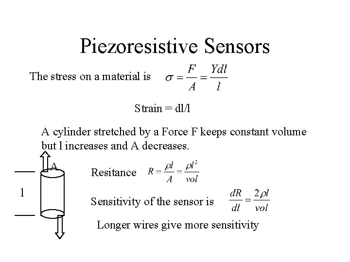
Piezoresistive Sensors The stress on a material is Strain = dl/l A cylinder stretched by a Force F keeps constant volume but l increases and A decreases. A l Resitance Sensitivity of the sensor is Longer wires give more sensitivity
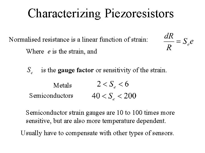
Characterizing Piezoresistors Normalised resistance is a linear function of strain: Where e is the strain, and is the gauge factor or sensitivity of the strain. Metals Semiconductor strain gauges are 10 to 100 times more sensitive, but are also more temperature dependent. Usually have to compensate with other types of sensors.
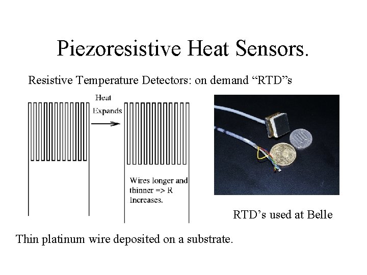
Piezoresistive Heat Sensors. Resistive Temperature Detectors: on demand “RTD”s RTD’s used at Belle Thin platinum wire deposited on a substrate.
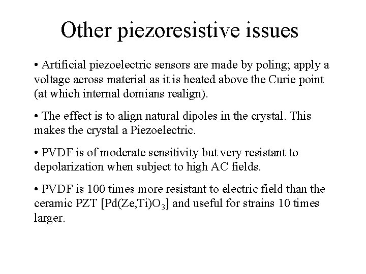
Other piezoresistive issues • Artificial piezoelectric sensors are made by poling; apply a voltage across material as it is heated above the Curie point (at which internal domians realign). • The effect is to align natural dipoles in the crystal. This makes the crystal a Piezoelectric. • PVDF is of moderate sensitivity but very resistant to depolarization when subject to high AC fields. • PVDF is 100 times more resistant to electric field than the ceramic PZT [Pd(Ze, Ti)O 3] and useful for strains 10 times larger.
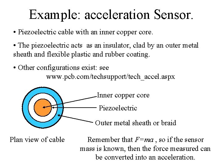
Example: acceleration Sensor. • Piezoelectric cable with an inner copper core. • The piezoelectric acts as an insulator, clad by an outer metal sheath and flexible plastic and rubber coating. • Other configurations exist: see www. pcb. com/techsupport/tech_accel. aspx Inner copper core Piezoelectric Outer metal sheath or braid Plan view of cable Remember that F=ma , so if the sensor mass is known, then the force measured can be converted into an acceleration.
Applications for piezoelectric accelerometers • Vibration monitor in compressor blades in turboshaft aircraft. • Detection of insects in silos • Automobile traffic analysis (buried in highway): traffic counting and weighing. • Force and pressure sensors (say, monitoring jolts to packages). • Tactile films: thin silicone rubber film (40 m) sandwiched between two thin PVDF films. If tactile sandwich is compressed, the mechanical coupling in the PVDF/rubber/PVDF sandwich changes, the measured AC signal changes, and the demodulation voltage changes
Lecture 5
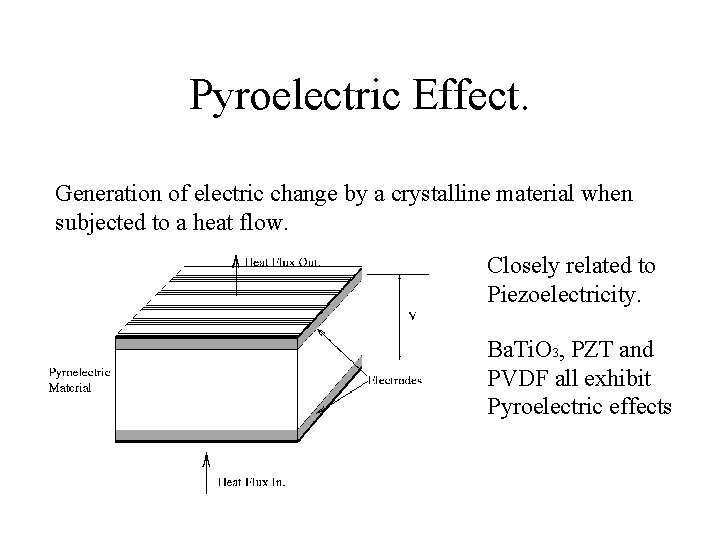
Pyroelectric Effect. Generation of electric change by a crystalline material when subjected to a heat flow. Closely related to Piezoelectricity. Ba. Ti. O 3, PZT and PVDF all exhibit Pyroelectric effects
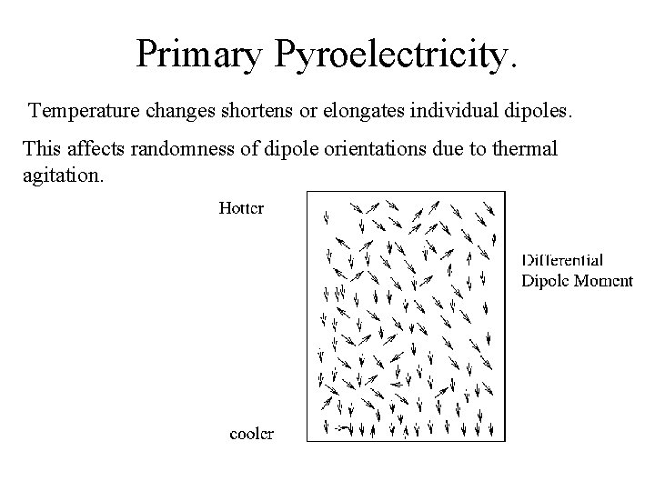
Primary Pyroelectricity. Temperature changes shortens or elongates individual dipoles. This affects randomness of dipole orientations due to thermal agitation.
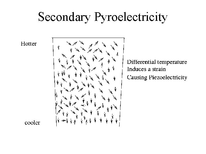
Secondary Pyroelectricity
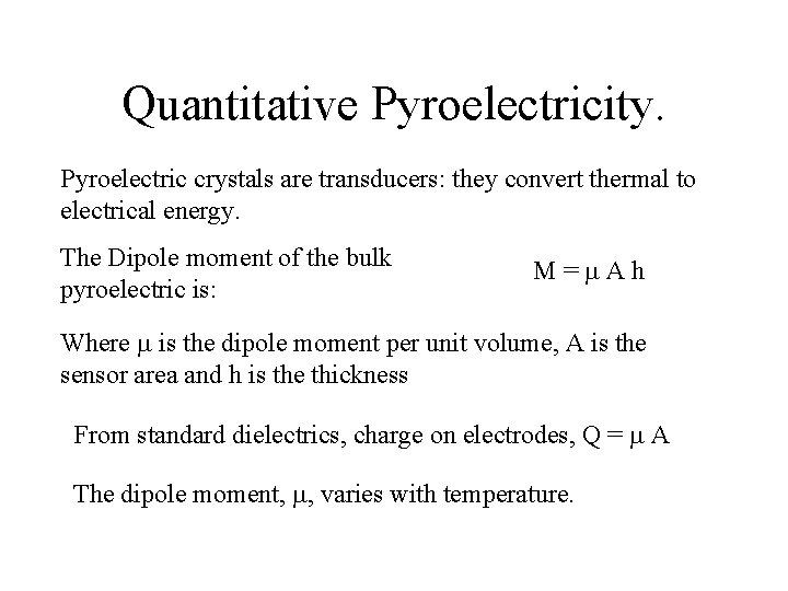
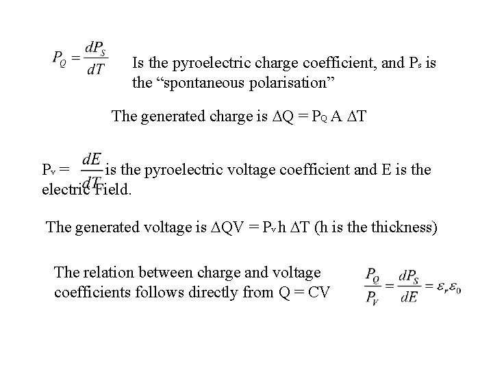
Quantitative Pyroelectricity. Pyroelectric crystals are transducers: they convert thermal to electrical energy. The Dipole moment of the bulk pyroelectric is: M= Ah Where is the dipole moment per unit volume, A is the sensor area and h is the thickness From standard dielectrics, charge on electrodes, Q = A The dipole moment, , varies with temperature.
Is the pyroelectric charge coefficient, and Ps is the “spontaneous polarisation” The generated charge is Q = PQ A T Pv = is the pyroelectric voltage coefficient and E is the electric Field. The generated voltage is QV = Pv h T (h is the thickness) The relation between charge and voltage coefficients follows directly from Q = CV
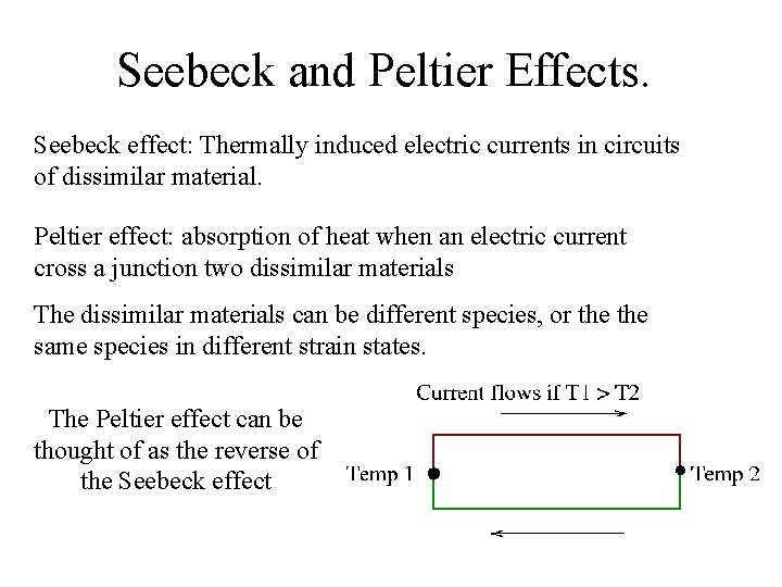
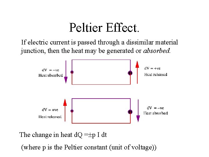
Seebeck and Peltier Effects. Seebeck effect: Thermally induced electric currents in circuits of dissimilar material. Peltier effect: absorption of heat when an electric current cross a junction two dissimilar materials The dissimilar materials can be different species, or the same species in different strain states. The Peltier effect can be thought of as the reverse of the Seebeck effect
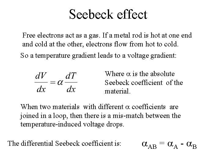
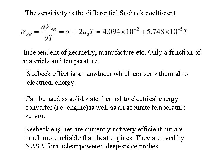
Seebeck effect Free electrons act as a gas. If a metal rod is hot at one end and cold at the other, electrons flow from hot to cold. So a temperature gradient leads to a voltage gradient: Where is the absolute Seebeck coefficient of the material. When two materials with different coefficients are joined in a loop, then there is a mis-match between the temperature-induced voltage drops. The differential Seebeck coefficient is: AB = A - B
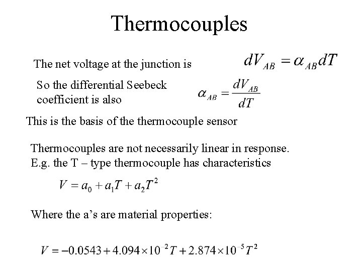
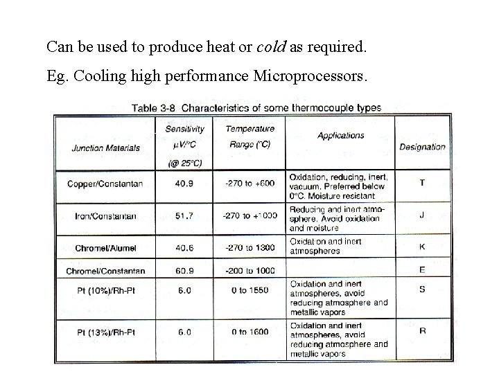
Thermocouples The net voltage at the junction is So the differential Seebeck coefficient is also This is the basis of thermocouple sensor Thermocouples are not necessarily linear in response. E. g. the T – type thermocouple has characteristics Where the a’s are material properties:
The sensitivity is the differential Seebeck coefficient Independent of geometry, manufacture etc. Only a function of materials and temperature. Seebeck effect is a transducer which converts thermal to electrical energy. Can be used as solid state thermal to electrical energy converter (i. e. engine)as well as an accurate temperature sensor. Seebeck engines are currently not very efficient but are much more reliable than heat engines. They are used by NASA for nuclear powered deep-space probes.
Peltier Effect. If electric current is passed through a dissimilar material junction, then the heat may be generated or absorbed. The change in heat d. Q = p I dt (where p is the Peltier constant (unit of voltage))
Can be used to produce heat or cold as required. Eg. Cooling high performance Microprocessors.
Lecture 6
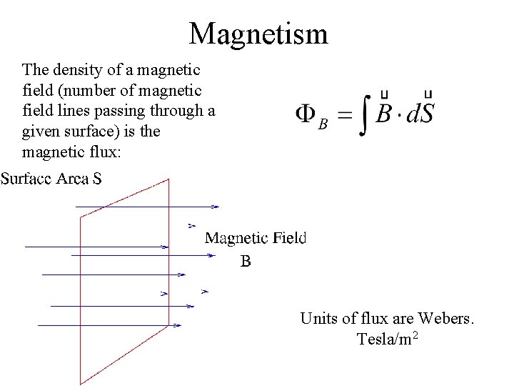
Magnetism The density of a magnetic field (number of magnetic field lines passing through a given surface) is the magnetic flux: Units of flux are Webers. Tesla/m 2
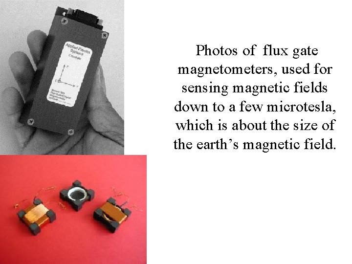
Photos of flux gate magnetometers, used for sensing magnetic fields down to a few microtesla, which is about the size of the earth’s magnetic field.
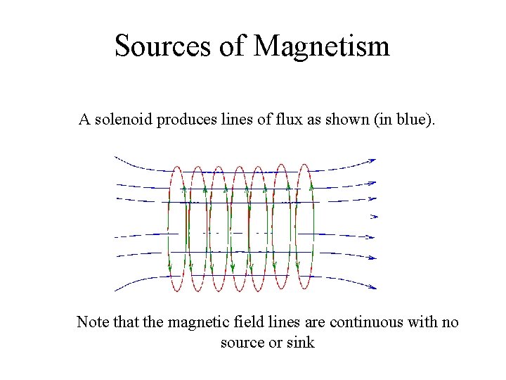
Sources of Magnetism A solenoid produces lines of flux as shown (in blue). Note that the magnetic field lines are continuous with no source or sink
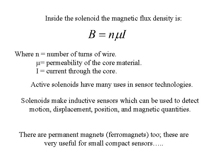
Inside the solenoid the magnetic flux density is: Where n = number of turns of wire. = permeability of the core material. I = current through the core. Active solenoids have many uses in sensor technologies. Solenoids make inductive sensors which can be used to detect motion, displacement, position, and magnetic quantities. There are permanent magnets (ferromagnets) too; these are very useful for small compact sensors…. .
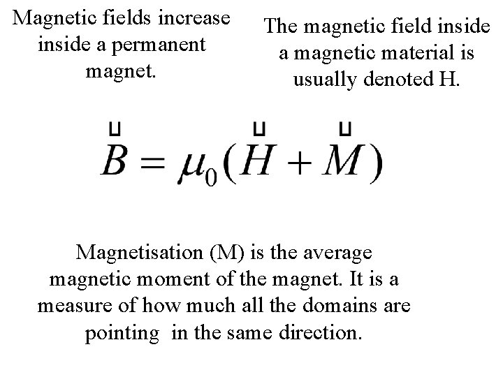
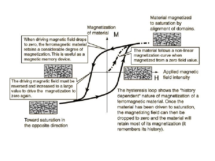
Magnetic fields increase inside a permanent magnet. The magnetic field inside a magnetic material is usually denoted H. Magnetisation (M) is the average magnetic moment of the magnet. It is a measure of how much all the domains are pointing in the same direction.
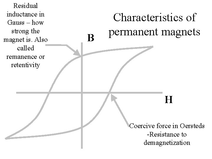
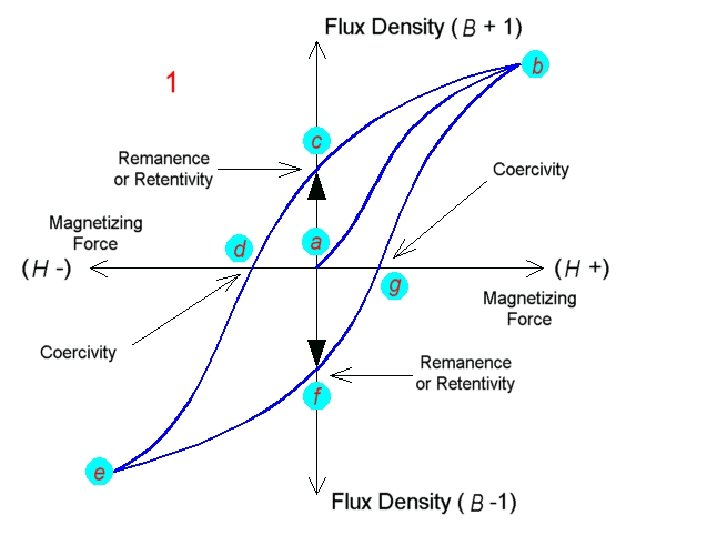
Residual inductance in Gauss – how strong the magnet is. Also called remanence or retentivity B Characteristics of permanent magnets H Coercive force in Oersteds -Resistance to demagnetization
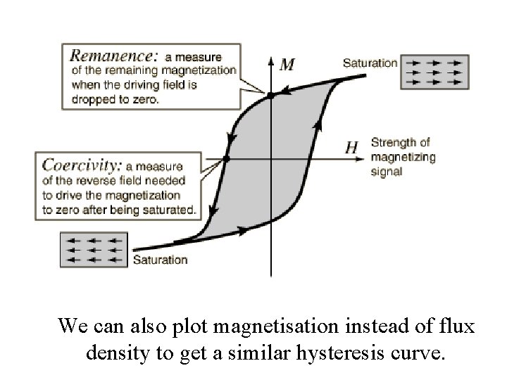
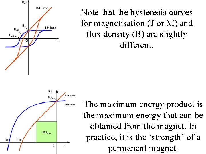
We can also plot magnetisation instead of flux density to get a similar hysteresis curve.
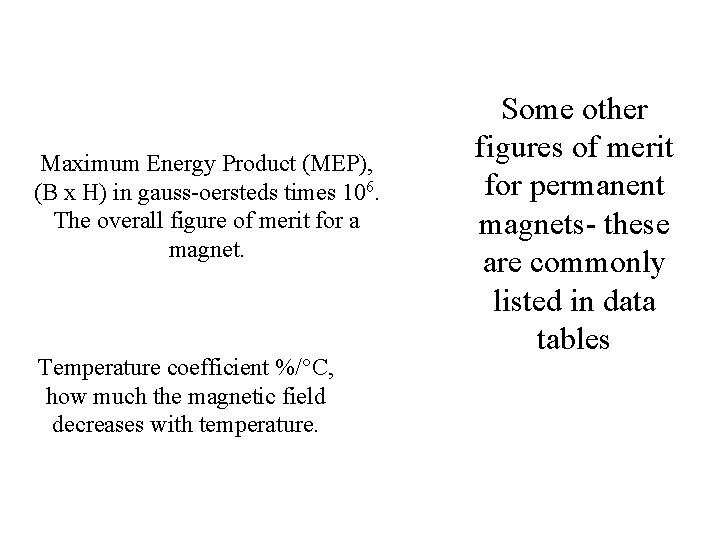
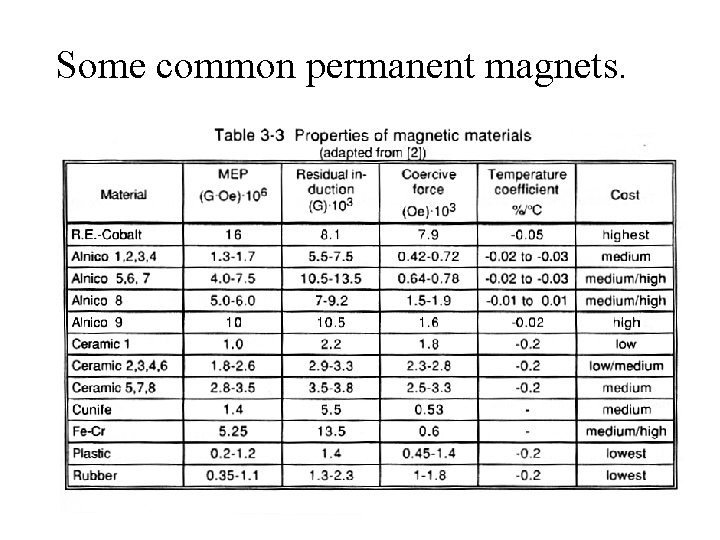
Maximum Energy Product (MEP), (B x H) in gauss-oersteds times 106. The overall figure of merit for a magnet. Temperature coefficient %/°C, how much the magnetic field decreases with temperature. Some other figures of merit for permanent magnets- these are commonly listed in data tables
Some common permanent magnets.
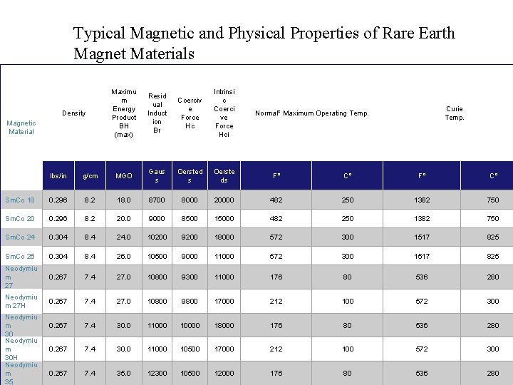
Typical Magnetic and Physical Properties of Rare Earth Magnet Materials Density Magnetic Material Maximu m Energy Product BH (max) Resid ual Induct ion Br Coerciv e Force Hc Intrinsi c Coerci ve Force Hci Curie Temp. Normal* Maximum Operating Temp. lbs/in g/cm MGO Gaus s Oersted s Oerste ds F° C° Sm. Co 18 0. 296 8. 2 18. 0 8700 8000 20000 482 250 1382 750 Sm. Co 20 0. 296 8. 2 20. 0 9000 8500 15000 482 250 1382 750 Sm. Co 24 0. 304 8. 4 24. 0 10200 9200 18000 572 300 1517 825 Sm. Co 26 0. 304 8. 4 26. 0 10500 9000 11000 572 300 1517 825 Neodymiu m 27 0. 267 7. 4 27. 0 10800 9300 11000 176 80 536 280 Neodymiu m 27 H 0. 267 7. 4 27. 0 10800 9800 17000 212 100 572 300 0. 267 7. 4 30. 0 110000 18000 176 80 536 280 0. 267 7. 4 30. 0 11000 10500 17000 212 100 572 300 0. 267 7. 4 35. 0 12300 10500 12000 176 80 536 280 Neodymiu m 30 H Neodymiu m 35
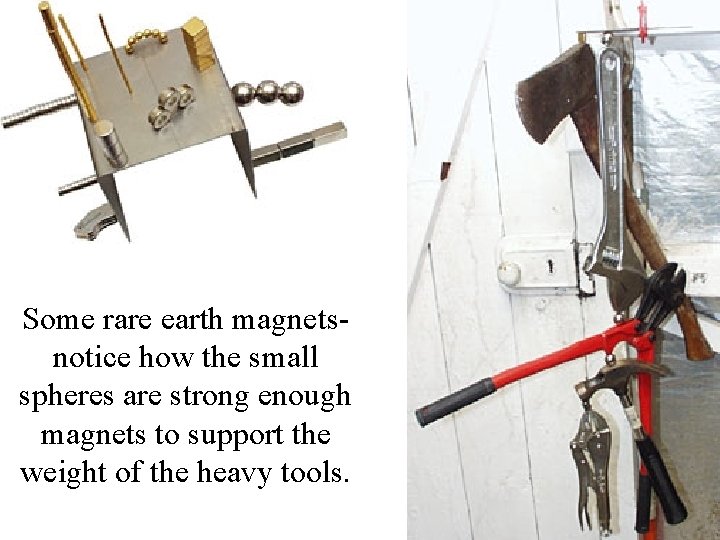
Some rare earth magnetsnotice how the small spheres are strong enough magnets to support the weight of the heavy tools.
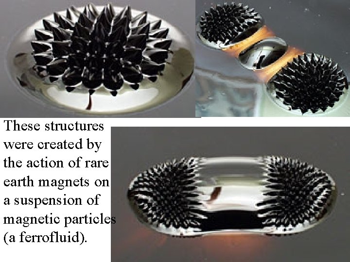
These structures were created by the action of rare earth magnets on a suspension of magnetic particles (a ferrofluid).
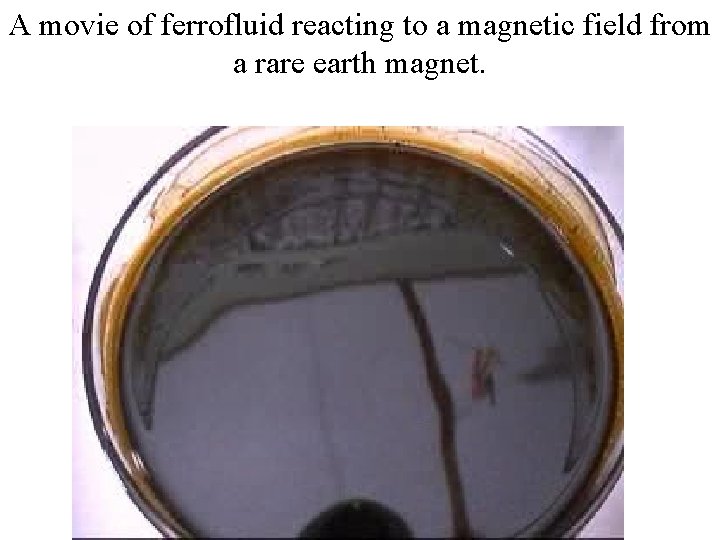
A movie of ferrofluid reacting to a magnetic field from a rare earth magnet.
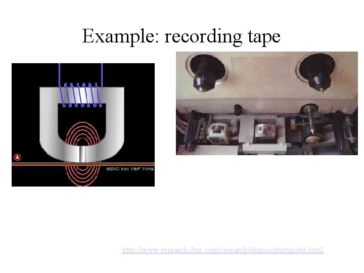
Hard disk reading heads use permanent magnets.
Note that the hysteresis curves for magnetisation (J or M) and flux density (B) are slightly different. The maximum energy product is the maximum energy that can be obtained from the magnet. In practice, it is the ‘strength’ of a permanent magnet.
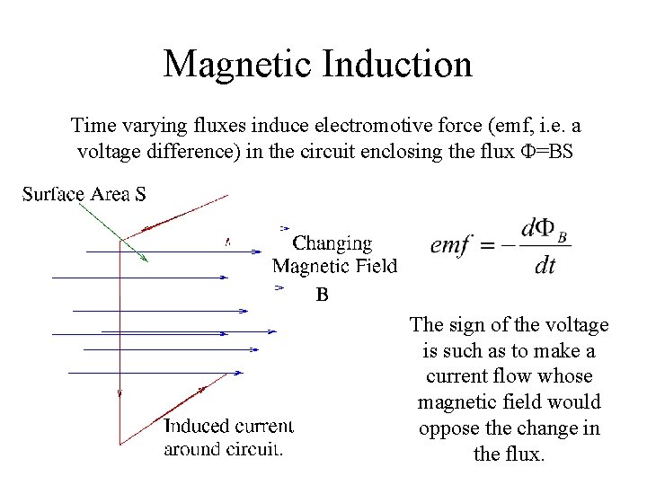
Magnetic Induction Time varying fluxes induce electromotive force (emf, i. e. a voltage difference) in the circuit enclosing the flux Φ=BS The sign of the voltage is such as to make a current flow whose magnetic field would oppose the change in the flux.
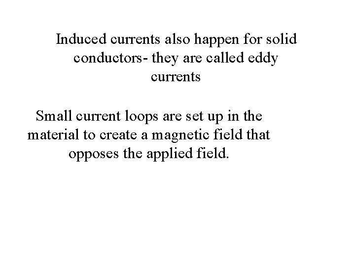
Induced currents also happen for solid conductors- they are called eddy currents Small current loops are set up in the material to create a magnetic field that opposes the applied field.
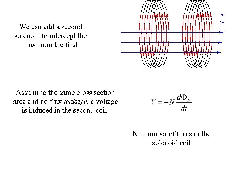
We can add a second solenoid to intercept the flux from the first Assuming the same cross section area and no flux leakage, a voltage is induced in the second coil: N= number of turns in the solenoid coil
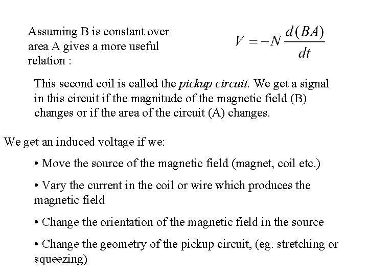
Assuming B is constant over area A gives a more useful relation : This second coil is called the pickup circuit. We get a signal in this circuit if the magnitude of the magnetic field (B) changes or if the area of the circuit (A) changes. We get an induced voltage if we: • Move the source of the magnetic field (magnet, coil etc. ) • Vary the current in the coil or wire which produces the magnetic field • Change the orientation of the magnetic field in the source • Change the geometry of the pickup circuit, (eg. stretching or squeezing)
Example: recording tape http: //www. research. ibm. com/research/demos/gmr/index. html
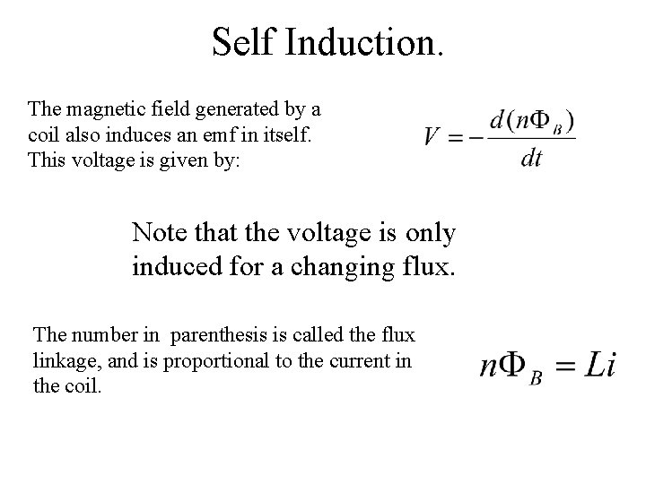
Self Induction. The magnetic field generated by a coil also induces an emf in itself. This voltage is given by: Note that the voltage is only induced for a changing flux. The number in parenthesis is called the flux linkage, and is proportional to the current in the coil.
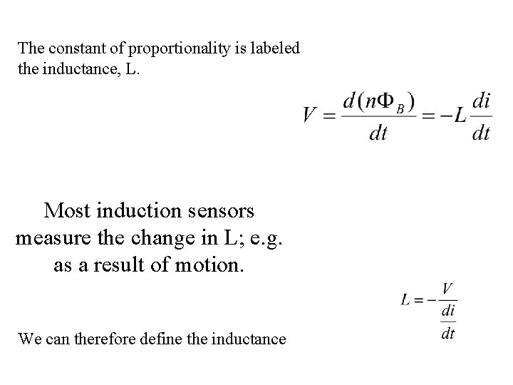
The constant of proportionality is labeled the inductance, L. Most induction sensors measure the change in L; e. g. as a result of motion. We can therefore define the inductance
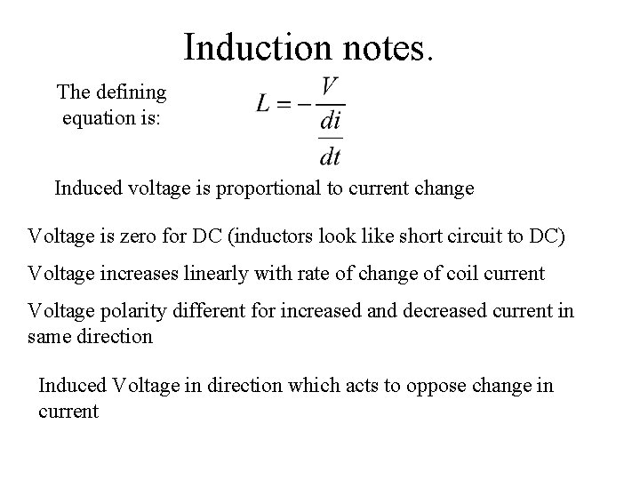
Induction notes. The defining equation is: Induced voltage is proportional to current change Voltage is zero for DC (inductors look like short circuit to DC) Voltage increases linearly with rate of change of coil current Voltage polarity different for increased and decreased current in same direction Induced Voltage in direction which acts to oppose change in current
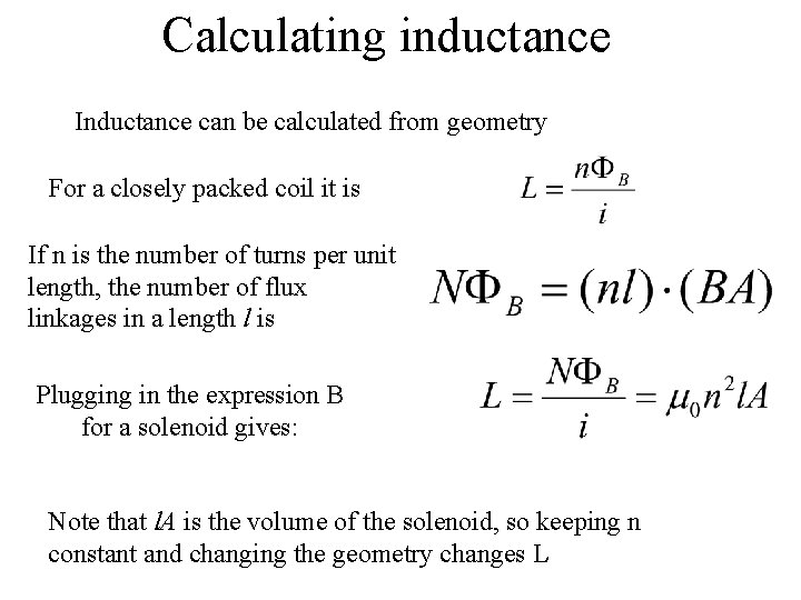
Calculating inductance Inductance can be calculated from geometry For a closely packed coil it is If n is the number of turns per unit length, the number of flux linkages in a length l is Plugging in the expression B for a solenoid gives: Note that l. A is the volume of the solenoid, so keeping n constant and changing the geometry changes L
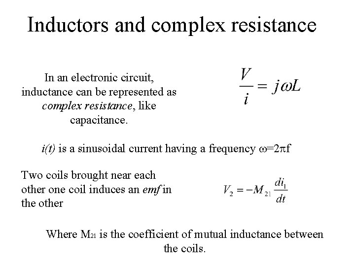
Inductors and complex resistance In an electronic circuit, inductance can be represented as complex resistance, like capacitance. i(t) is a sinusoidal current having a frequency =2 f Two coils brought near each other one coil induces an emf in the other Where M 21 is the coefficient of mutual inductance between the coils.
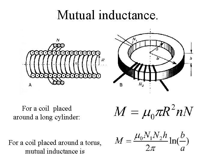
Mutual inductance. For a coil placed around a long cylinder: For a coil placed around a torus, mutual inductance is
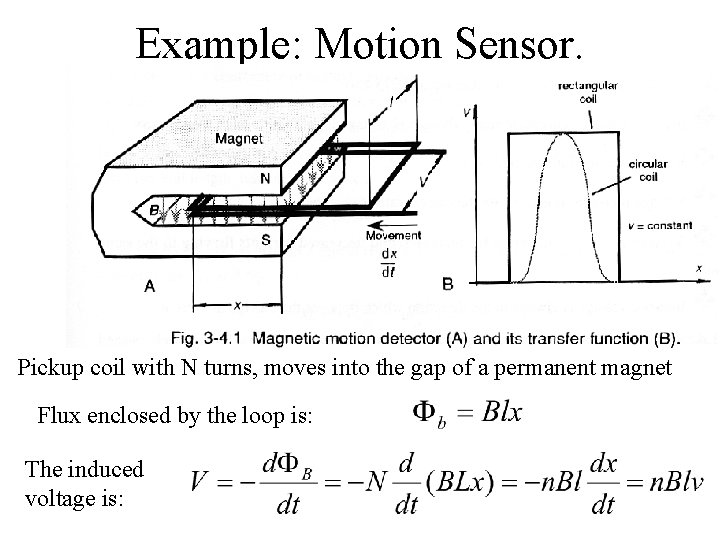
Example: Motion Sensor. Pickup coil with N turns, moves into the gap of a permanent magnet Flux enclosed by the loop is: The induced voltage is:
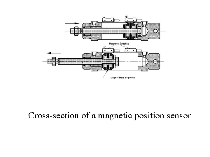
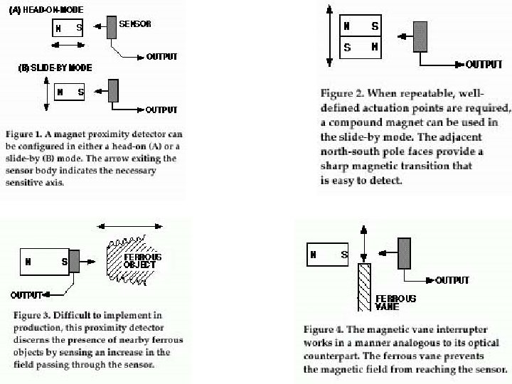
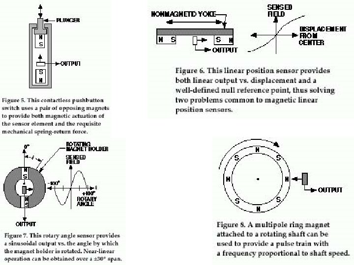
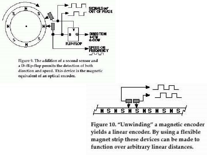
Cross-section of a magnetic position sensor
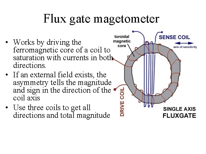
Flux gate magetometer • Works by driving the ferromagnetic core of a coil to saturation with currents in both directions. • If an external field exists, the asymmetry tells the magnitude and sign in the direction of the coil axis • Use three coils to get all directions and total magnitude
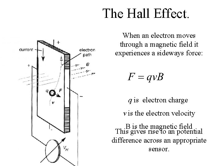
The Hall Effect. When an electron moves through a magnetic field it experiences a sideways force: q is electron charge v is the electron velocity B is the magnetic field This gives rise to an potential difference across an appropriate sensor.
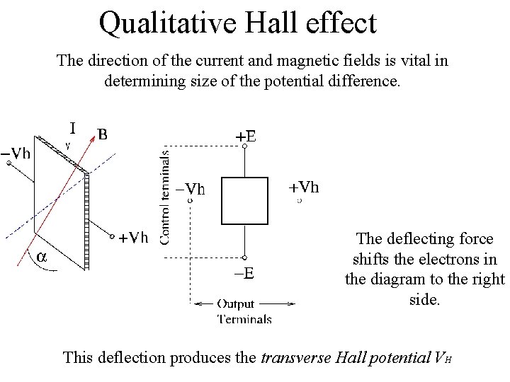
Qualitative Hall effect The direction of the current and magnetic fields is vital in determining size of the potential difference. The deflecting force shifts the electrons in the diagram to the right side. This deflection produces the transverse Hall potential VH
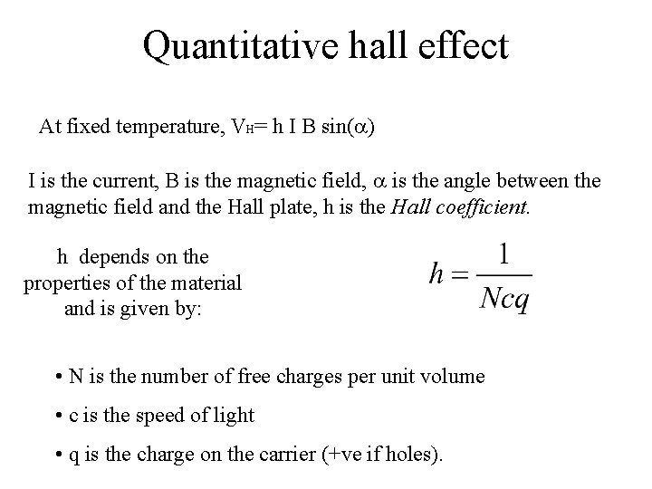
Quantitative hall effect At fixed temperature, VH= h I B sin( ) I is the current, B is the magnetic field, is the angle between the magnetic field and the Hall plate, h is the Hall coefficient. h depends on the properties of the material and is given by: • N is the number of free charges per unit volume • c is the speed of light • q is the charge on the carrier (+ve if holes).
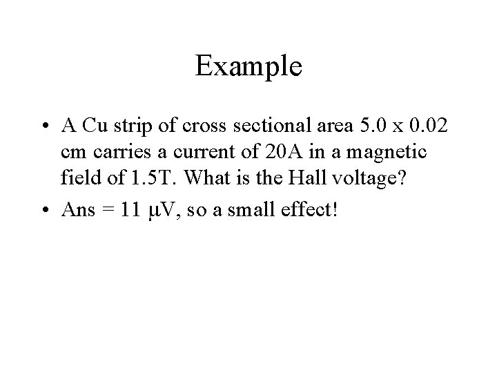
Example • A Cu strip of cross sectional area 5. 0 x 0. 02 cm carries a current of 20 A in a magnetic field of 1. 5 T. What is the Hall voltage? • Ans = 11 V, so a small effect!
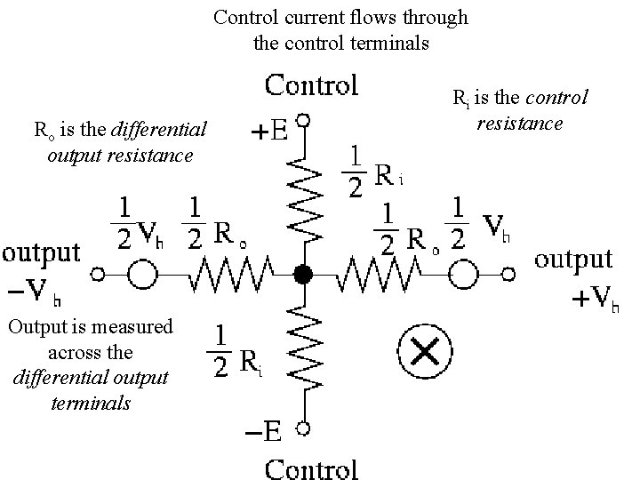
Control current flows through the control terminals Ro is the differential output resistance Output is measured across the differential output terminals Ri is the control resistance
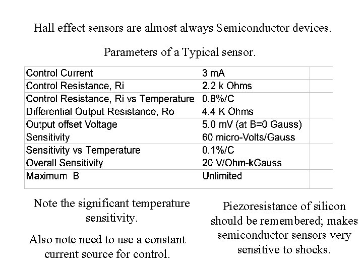
Hall effect sensors are almost always Semiconductor devices. Parameters of a Typical sensor. Note the significant temperature sensitivity. Also note need to use a constant current source for control. Piezoresistance of silicon should be remembered; makes semiconductor sensors very sensitive to shocks.
End of Electrical sensors Summary: • Magnetism essentials • Permanent Magnets • Inductance • Hall effect