Lecture 3 Cloud Infrastructure Cloud Overview Data Center


 • Supply virtualized resources, e.")


 Networking Goals • • Connectivity – inside, outside, no loops, etc.")


 (Uploads) - Transferred from en. wikipedia to Commons. ,")


2 core routers Fat Tree (K=4) Note the replacement of aggregation layer switches with")
")
 or will have a")


")


- Slides: 37
Lecture 3: Cloud Infrastructure Cloud Overview Data Center Network Architecture
Socrative • www. socrative. com • Room: CMU 14848 • https: //api. socrative. com/rc/Nfu 6 Lp
What Is “The Cloud”? • Back in the day, the providers of each service owned/operated the means of production. • Cloud Computing is a model that enables a separation between the ends and the means • But, it is more than remote or distributed computing and storage • Key Properties: • Elastic: ability to scale up or scale down • Metered (“Utility Computing”): Pay (only) for what is used • Self-Service: Users have the knobs and reasonable models for using them • Frameworks/Services: Reducing complexity and providing an accessible, powerful model
Service Models • Infrastructure as a Service (Iaa. S) • Supply virtualized resources, e. g. S 3 or EC 2 • Platform as a service (Paa. S) • Let users focus on what they are delivering, not the resources needed to deliver it, e. g. Google’s App. Engine, Salesforce, Microsoft Azure, Amazon Web Services • Software as a Service (Saa. S) • Software is delivered via the cloud, e. g. fee for use. Consider Google. Apps, Microsoft 360, etc.
Key Idea: Sharing • Uses share many units of production (compute servers, storage servers, etc) • “Multi-Tenancy” • Ability to allocate resources for need • Ability to interchange parts for maintenance and resilience • Multi-tenancy • Sharing and amortizing costs for efficiency, allow for averaging bursts • Independent users result in need for security and isolation
The Cloud Stack • • • Application Transport Network Link Physical • • • Applications Frameworks Virtualization Services Compute and Storage Servers Coordination Services Storage Services (File, Object, Database) Transport Network Link Physical
Networking For The Cloud • Within Data Center • With luck, hosts resources commonly used together • Long Haul, Across Data Centers • Services, when possible, co-located with the resources they need • Global services
DC Networking vs Long Haul Network • Long haul: Speed of light is significant source of latency, unlikely to be resolved soon • With a DC, distances are short, the speed of light is less of a factor • Serialization/Deserialization delay (bits/second) is a factor • Long haul: Shortest path is not uncommon and likely best • Within a DC, tree-like topologies can concentrate traffic, generating bottle necks
Data Center (DC) Networking Goals • • Connectivity – inside, outside, no loops, etc. Efficiency – short paths, no hot spots, etc. Self configuring – Humans effort can’t be scaled in this way Robust – Consequences of failure aren’t disproportional; Failure is recoverable • VMs and Migration – Network structure doesn’t compartmentalize VMs • Commodity hardware – Certainly facilitates adoption
Implications • Connectivity – Scale and hierarchy requires big routing/forwarding tables • • • or impossibly large flat space. Routing protocols adapt to change slowly, leaving temporary inconsistency, e. g. loops, from failure and other changes. Efficiency – Look toward fat trees, clos networks Self-configuring – Look toward a discovery protocol, p 2 p or coordinated Robust – Rapidly learn changed, avoid single points of failure w/high responsibility Migration – Want a flat address space to avoid compartmentalization. Trying to fix above IP layer is a mess as it all comes back down and has to find its way. Commodity hardware – Services provided in off-switch software
DC Networking over time • Flat – Gee whiz! We have a LAN! • Ut-Oh! Too many addresses to remember what to do with them all, never mind to manage each one individually • Hierarchical – Look ma’! Global scale! • Ut-Oh! Hierarchy requires management. Creates hot spots and fragments address space. IP addresses limit migration. Forwarding is painful. • Fat Tree – Many roots means many paths, relieves hot spots • Still hierarchical. Still fragment. Still needs managing. Etc.
Network Switches • Ports connect to network segments • Hosts and uplink at leaf level • Other switches at other levels • Switches have to move messages (frames, packets, etc) from one port to another • Hardware solutions: Crossbar, etc • Shared memory solutions: input and output queues • Limited throughput (processor time, shared memory, crossbar, etc) • Limited number of ports, limited throughput per port, limited aggregate throughput • Commodity-level capacities are relatively affordable • Trying to buy more capacity is expensive with limited gain
DC Topology: Venerable 3 -Tier • Since, beyond a certain point, we can’t make switches wider and/or faster, we need to “fan out”, most commonly with a tree topology • Venerable 3 -tier network is a straight-forward example: Core Aggregation Leaf
DC Topology: Venerable 3 -Tier • Can add a redundant core for increased throughput and resiliance Core Aggregation Leaf
DC Topology: Venerable 3 -Tier • Scales nicely, but … • Higher up gets over-subscribed since everything passes through • Over-subscription increases with scale • Request-to-stream and host-to-host cases generate bottlenecks 1 x Switch Throughput W 2 x Switch Throughput
Clos Networks By Piggly (talk) (Uploads) - Transferred from en. wikipedia to Commons. , Public Domain, https: //commons. wikimedia. org/w/index. php? curid=61536102 • Allocating an input port, and associated throughput, • Allocates path whole way through. • Nx. N connectivity with switches with less than Nx. N connectivity • Basically a way to make a large Nx. N switch • Still an expensive expansion and not likely to need all throughput capacity simultaneously
Leaf and Spine
Leaf and Spine • Type of Clos network • • Essentially folded, but still N-to-N connections • Derived from old phone company architecture, invented in 1950 s. All paths are same length from edge to edge Great for switch vendors Need to pick path, as can choose any middle router Very redundant Can implement at layer-2 or layer-3 More soon
Fat-Tree Networks • More throughput at higher levels, more even across levels • Not easy to do since buying more powerful switches is harder • To extent possible, more cost per unit capacity • Not possible beyond a modest point • This is somewhat necessarily the case as, if bigger switches were more readily available and economical, they’d be used at the bottom, and we’d be back where we started.
Fat-Trees With Skinny Switches: Goals • • Use all commodity switches Full throughput from host-to-host Compatible with usual TCP/IP stack Better energy efficiency per unit throughput from more smaller switches than fewer bigger switches
(K/2)2 core routers Fat Tree (K=4) Note the replacement of aggregation layer switches with 2 layers of K/2 K-port switches (K/2)2 servers per pod K-port switches support K 3/4 servers
Fat Tree Details • • • K-ary fat free: three layers (core, aggregation, edge) Each pod consists of (K/2)2 servers and 2 layers of K/2 K-port switches. Each edge switch connects (K/2) servers to (K/2) aggregator switches Each aggregator switch connects (K/2) edge and (K/2) core switches (K/2)2 core switches, each ultimately connecting to K pods • Providing K different roots, not 1. Trick is to pick different ones • K-port switches support K 3/4 servers/host: • (K/2 hosts/switch * K/2 switches per pod * K pods)
Using Multiple Paths • Must pick different paths (“path diversity”) or will have a hotspot • Unless sessions use the same path, reordering will be a problem and need to be resolved with buffering higher up • Static paths may not respond to actual, dynamic workloads • Can be done at different levels. • Higher levels, e. g. transport, are more flexible, but likely more effort and slower • Lower levels are likely less adaptive, but simpler and faster. • Ability to weight or remove paths can aid fault tolerance
Portland Solution • Use commodity switches and off-load services into software on commodity server • Start With Fat Tree for a topology without hot spots • Use layer-2 to avoid routing, forwarding, and related complexity • Separate host identifier from host location • IP addresses identify host, but not location, just and ID • Use “Pseudo MAC Address” to identify location at Level-2
Port. Land Addresses • Normally MAC addresses are arbitrary – no clue about location • IP normally is hierarchical, but here we are using it only as a host identifier • If MAC addresses are not tied to location, switch tables grow linearly with growth of network, i. e. O(n) • Port. Land uses hierarchical MAC addresses, called “Pseudo MAC” or PMAC addresses to provide for switch location • <pod: port: position: vmid> • <16, 8, 8, 16> bits
0 2 Positio n Port. Land PMAC Addresses 1 3 0 1 0 PMAC: <pod. position. port. vmid> 1 0 1 48 bits: <16 -bits. 8 -bits. 16 -bits>
Portland PMAC Addresses
VM Migration • Flat address space. • IP address unchanged after migration, higher level doesn’t see state change • • After migration IP<->PMAC changes, as PMAC is location dependent VM sends gratuitous ARP with new mapping. Fabric Manager receives ARP and sends invalidation to old switch Old switch sets flow table to software, causing ARP to be sent to any stray packets • Forwarding the packet is optional, as retransmit (if reliable) will fix delivery
Location Discovery: Configuring Switch IDs • Humans = Not right Answer • Discovery = Right Answer • Send messages to neighbors – Get Tree Level • Hosts don’t reply, so edge only hears back from above • Aggregate hears back from both levels • Core hears back only from aggregate • Contact Fabric Manager with tree level to get ID • Fabric Manager is service running on commodity host • Assigns ID
Name Resolution: MAC PMAC IP • End hosts continue to use Actual MAC (AMAC) addresses • Switches convert PMAC<->AMAC for the host • Edge switch responsible for creating PMAC: AMAC mapping and telling Fabric Manager • Software on commodity server, can be replicated, etc. Simplicity is a virtue. • Mappings timed out of Fabric Manager’s cache, if not used. • ARPs are for PMACs • First ask fabric manager which keeps cache. Then, if needed, broadcast.
No loops, No Spanning Trees • Forwarding can only go up the tree. • Cycles not possible.
Failure • • Keep-alives like the link discovery messages Miss a keep alive? Tattle to the Fabric Manager Fabric manager tells effected switches, which adjust own tables. O(N) vs O(N 2) for traditional routing algorithms (Fabric Manager tells every switch vs every switch tells every switch)
Looking Back • Connectivity – Hosts can talk! No possibility of loops • Efficiency – Much less memory needed in switches, O(N) fault handlingh • Self configuring – Discovery protocol + ARP • Robust – Failure handling coordinated by FM • VMs and Migration – Each has own IP address, each has own MAC address • Commodity hardware – Nothing magic.
Flow Classification • Type of “diffusion optimization” • Mitigate local congestion • Assign traffic to ports based upon flow, not host. • One host can have many flows, thus many assigned routings • Fairly distribute flows • (K/2)2 shortest paths available – but doesn’t help if all pick same one, e. g. same root of multi-rooted tree • Periodically reassign output port to free up corresponding input port
Flow Scheduling • Also a “Diffusion Optimization” • Detect and deconflict large, long-lived flows • Threshholds for throughput and longevity
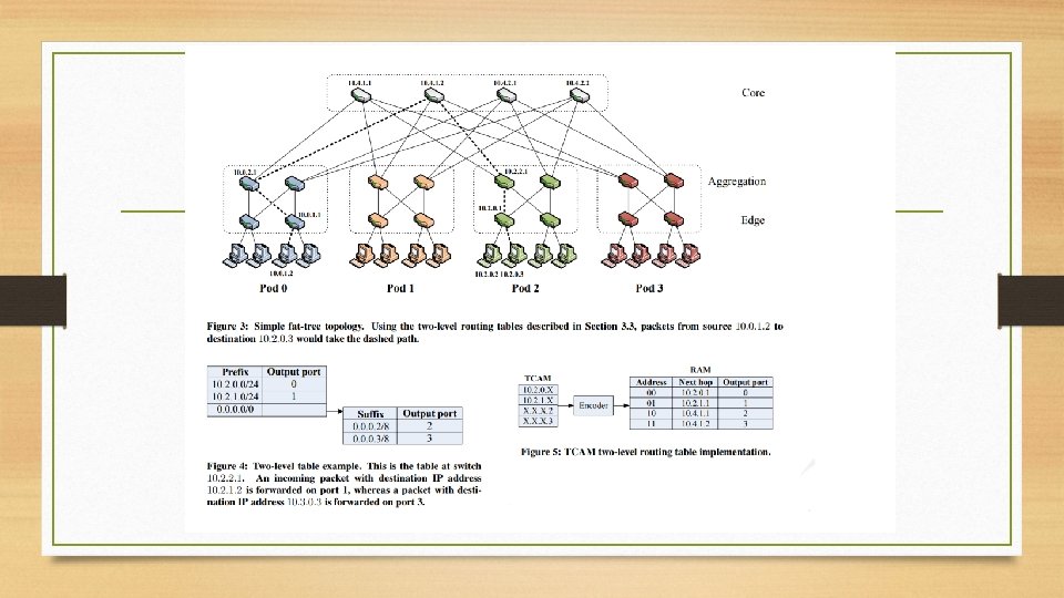
Fat-Tree Solution: “Special” IP Addressing • “ 10. 0/8” private addresses • Pod-level uses “ 10. pod. switch. 1“ • pod, switch < K • Core-level uses "10. K. j. i“ • K is the same K as elsewhere, the number of ports/switch • View cores as logical square. i, j denote position in square. • Hosts use “ 10. pod. switch. ID" addresses • 2 <= ID <= (K/2) • K=1 is pod-level switch; ID > 2 is too many hosts • 8 -bits implies K < 256 • Will pre-bake the paths to ensure diversity, while maintaining ordering