
Lecture 26 ECE 743 3 Phase Induction Machines
- Slides: 32
Lecture 26 - ECE 743 3 -Phase Induction Machines Reference Frame Theory – Part I Professor: Ali Keyhani
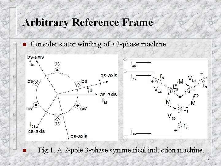
Arbitrary Reference Frame n n Consider stator winding of a 3 -phase machine Fig. 1. A 2 -pole 3 -phase symmetrical induction machine. 2
Arbitrary Reference Frame n Synchronous and induction machine inductances are functions of the rotor speed, therefore the coefficients of the differential equations (voltage equations) which describe the behavior of these machines are time-varying. n A change of variables can be used to reduce the complexity of machine differential equations, and represent these equations in another refernce frame with constant coefficients. 3
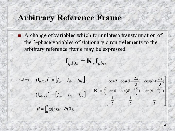
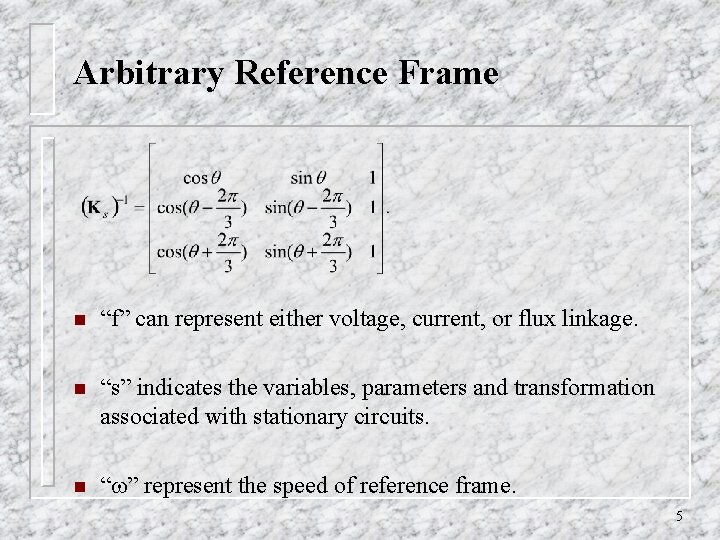
Arbitrary Reference Frame n A change of variables which formulatesa transformation of the 3 -phase variables of stationary circuit elements to the arbitrary reference frame may be expressed 4
Arbitrary Reference Frame n “f” can represent either voltage, current, or flux linkage. n “s” indicates the variables, parameters and transformation associated with stationary circuits. n “ ” represent the speed of reference frame. 5
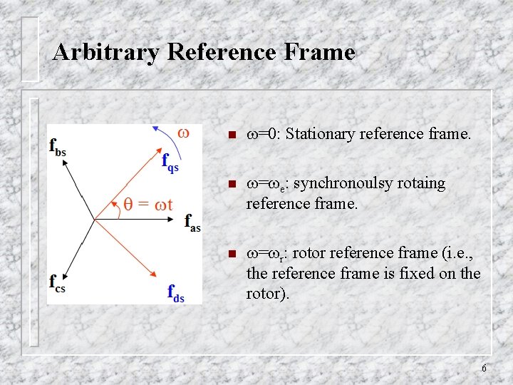
Arbitrary Reference Frame n =0: Stationary reference frame. n = e: synchronoulsy rotaing reference frame. n = r: rotor reference frame (i. e. , the reference frame is fixed on the rotor). 6
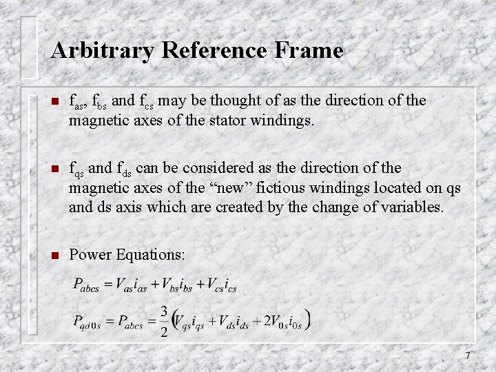
Arbitrary Reference Frame n fas, fbs and fcs may be thought of as the direction of the magnetic axes of the stator windings. n fqs and fds can be considered as the direction of the magnetic axes of the “new” fictious windings located on qs and ds axis which are created by the change of variables. n Power Equations: 7
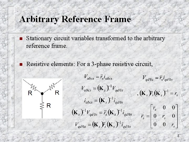
Arbitrary Reference Frame n Stationary circuit variables transformed to the arbitrary reference frame. n Resistive elements: For a 3 -phase resistive circuit, 8
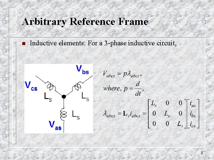
Arbitrary Reference Frame n Inductive elements: For a 3 -phase inductive circuit, 9
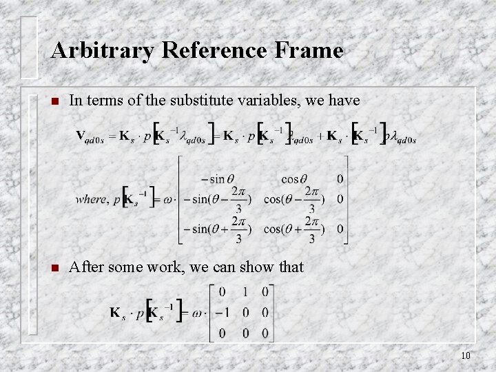
Arbitrary Reference Frame n In terms of the substitute variables, we have n After some work, we can show that 10
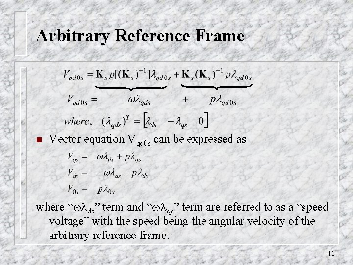
Arbitrary Reference Frame n Vector equation Vqd 0 s can be expressed as where “ ds” term and “ qs” term are referred to as a “speed voltage” with the speed being the angular velocity of the arbitrary reference frame. 11
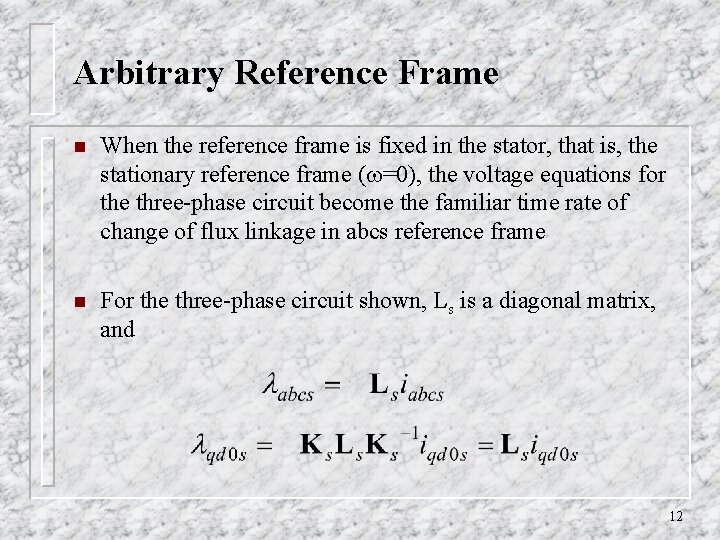
Arbitrary Reference Frame n When the reference frame is fixed in the stator, that is, the stationary reference frame ( =0), the voltage equations for the three-phase circuit become the familiar time rate of change of flux linkage in abcs reference frame n For the three-phase circuit shown, Ls is a diagonal matrix, and 12
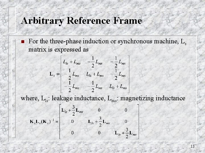
Arbitrary Reference Frame n For the three-phase induction or synchronous machine, Ls matrix is expressed as where, Lls: leakage inductance, Lms: magnetizing inductance 13
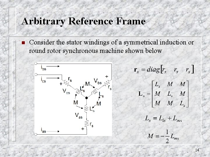
Arbitrary Reference Frame n Consider the stator windings of a symmetrical induction or round rotor synchronous machine shown below 14
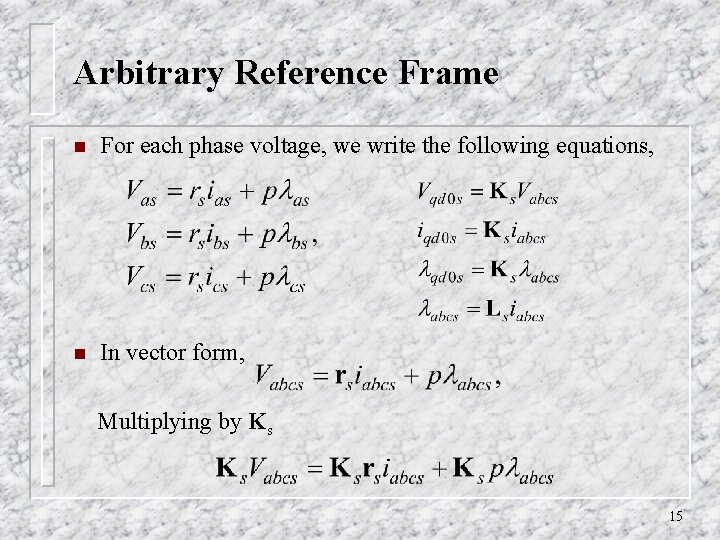
Arbitrary Reference Frame n For each phase voltage, we write the following equations, n In vector form, Multiplying by Ks 15
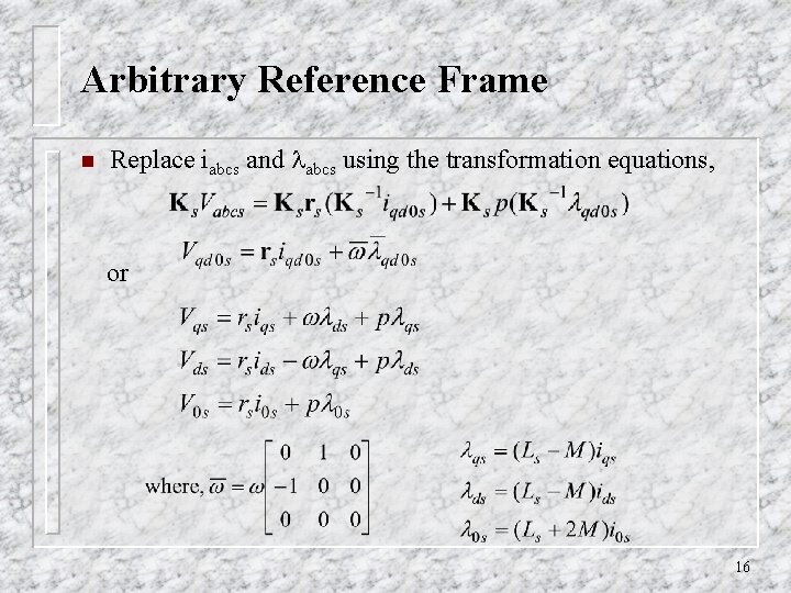
Arbitrary Reference Frame n Replace iabcs and abcs using the transformation equations, or 16
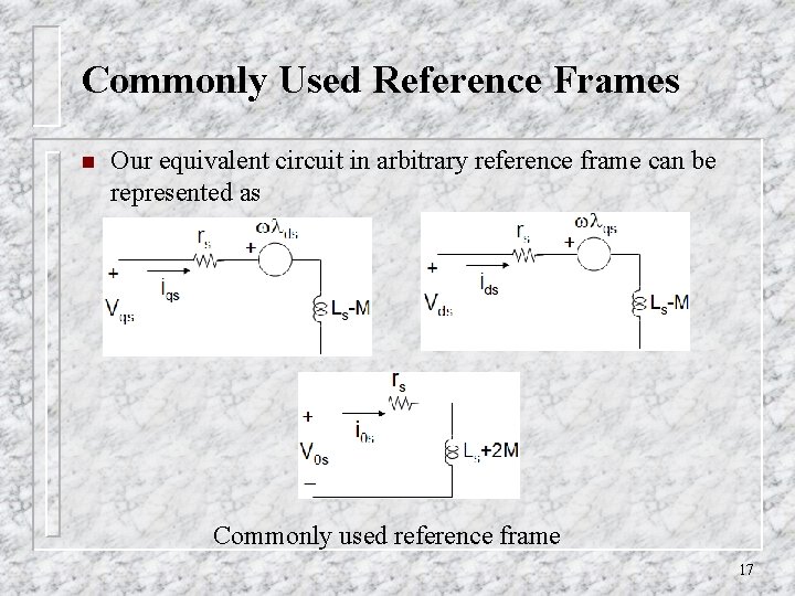
Commonly Used Reference Frames n Our equivalent circuit in arbitrary reference frame can be represented as Commonly used reference frame 17
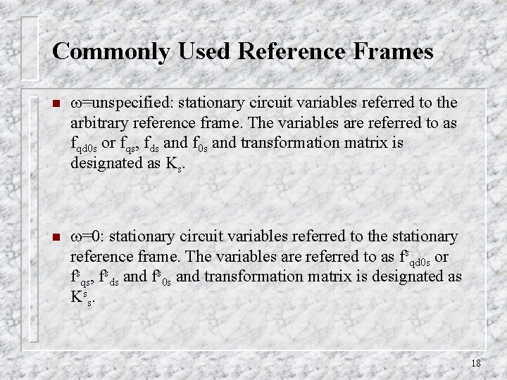
Commonly Used Reference Frames n =unspecified: stationary circuit variables referred to the arbitrary reference frame. The variables are referred to as fqd 0 s or fqs, fds and f 0 s and transformation matrix is designated as Ks. n =0: stationary circuit variables referred to the stationary reference frame. The variables are referred to as fsqd 0 s or fsqs, fsds and fs 0 s and transformation matrix is designated as K ss. 18
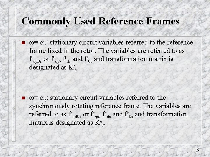
Commonly Used Reference Frames n = r: stationary circuit variables referred to the reference frame fixed in the rotor. The variables are referred to as frqd 0 s or frqs, frds and fr 0 s and transformation matrix is designated as Krs. n = e: stationary circuit variables referred to the synchronously rotating reference frame. The variables are referred to as feqd 0 s or feqs, feds and fe 0 s and transformation matrix is designated as Kes. 19
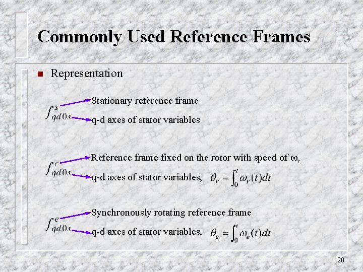
Commonly Used Reference Frames n Representation Stationary reference frame q-d axes of stator variables Reference frame fixed on the rotor with speed of r q-d axes of stator variables, Synchronously rotating reference frame q-d axes of stator variables, 20
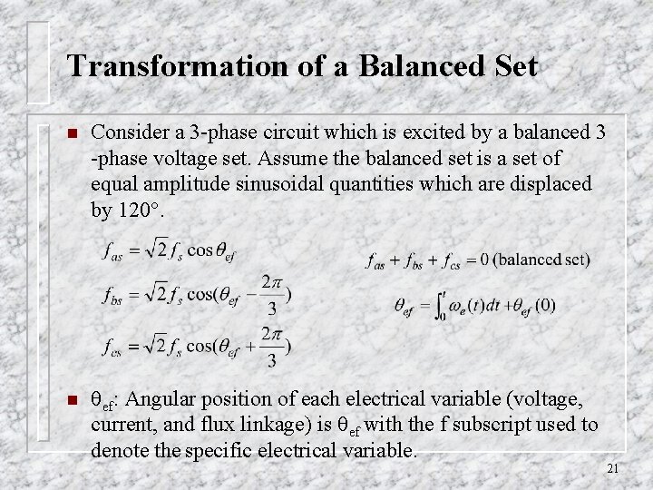
Transformation of a Balanced Set n Consider a 3 -phase circuit which is excited by a balanced 3 -phase voltage set. Assume the balanced set is a set of equal amplitude sinusoidal quantities which are displaced by 120. n ef: Angular position of each electrical variable (voltage, current, and flux linkage) is ef with the f subscript used to denote the specific electrical variable. 21
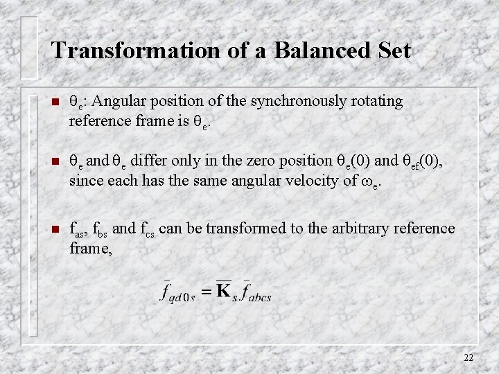
Transformation of a Balanced Set n e: Angular position of the synchronously rotating reference frame is e. n e and e differ only in the zero position e(0) and ef(0), since each has the same angular velocity of e. n fas, fbs and fcs can be transformed to the arbitrary reference frame, 22
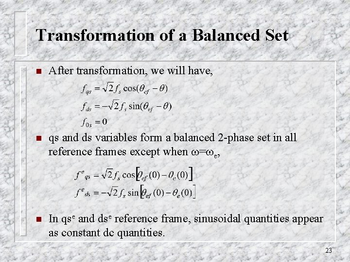
Transformation of a Balanced Set n After transformation, we will have, n qs and ds variables form a balanced 2 -phase set in all reference frames except when = e, n In qse and dse reference frame, sinusoidal quantities appear as constant dc quantities. 23
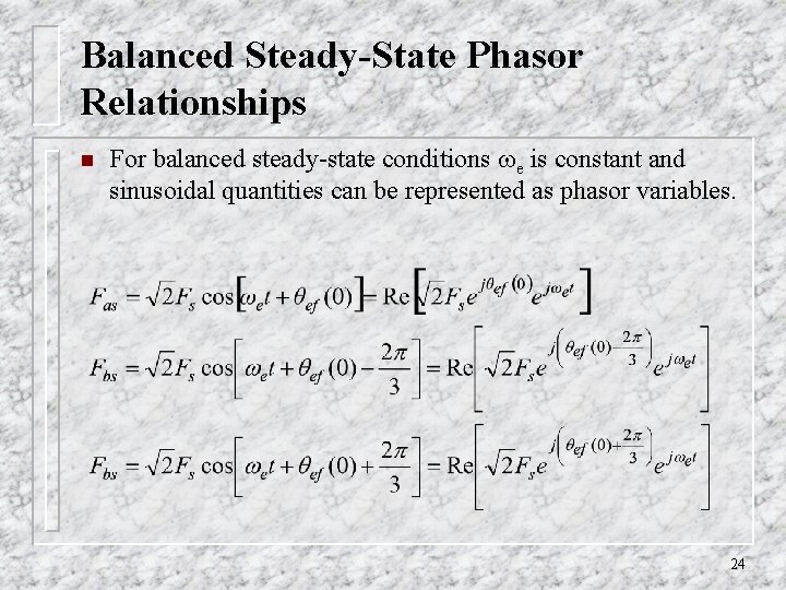
Balanced Steady-State Phasor Relationships n For balanced steady-state conditions e is constant and sinusoidal quantities can be represented as phasor variables. 24
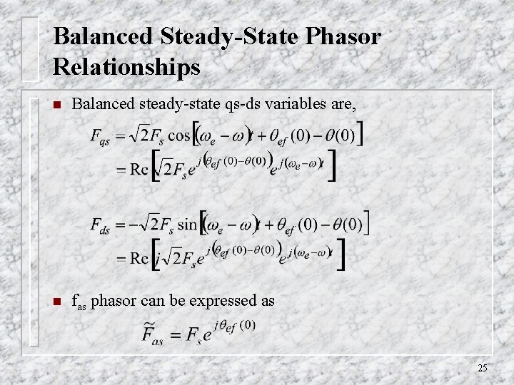
Balanced Steady-State Phasor Relationships n Balanced steady-state qs-ds variables are, n fas phasor can be expressed as 25
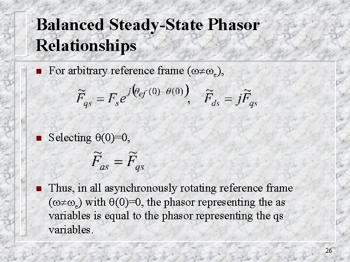
Balanced Steady-State Phasor Relationships n For arbitrary reference frame ( e), n Selecting (0)=0, n Thus, in all asynchronously rotating reference frame ( e) with (0)=0, the phasor representing the as variables is equal to the phasor representing the qs variables. 26
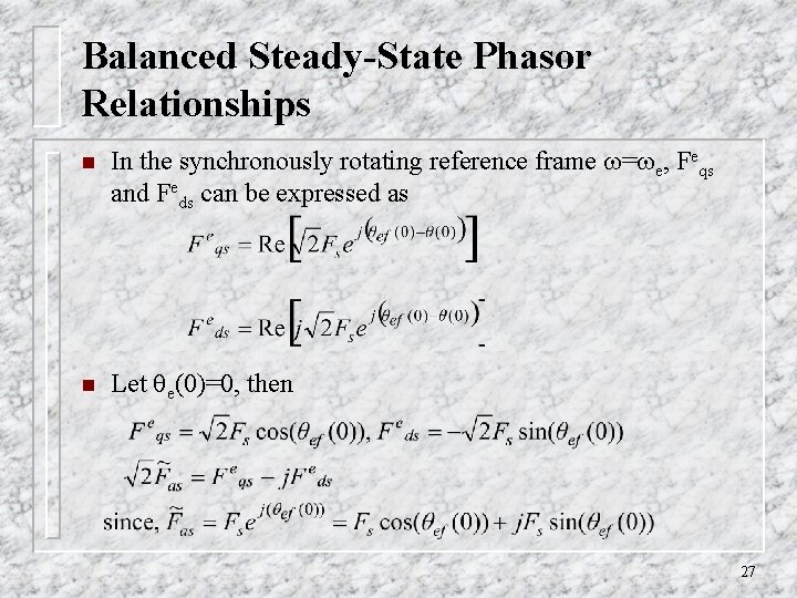
Balanced Steady-State Phasor Relationships n In the synchronously rotating reference frame = e, Feqs and Feds can be expressed as n Let e(0)=0, then 27
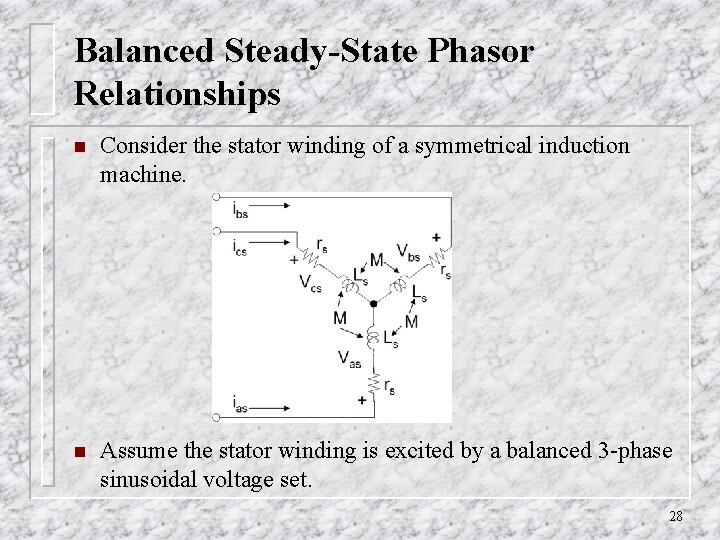
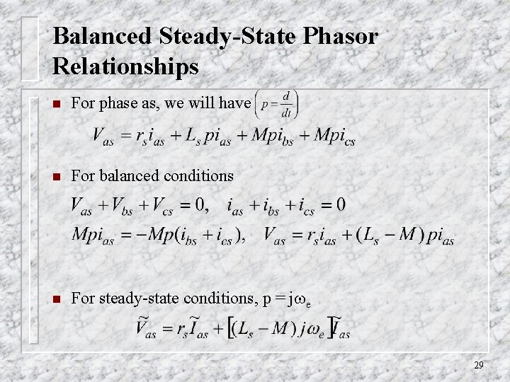
Balanced Steady-State Phasor Relationships n Consider the stator winding of a symmetrical induction machine. n Assume the stator winding is excited by a balanced 3 -phase sinusoidal voltage set. 28
Balanced Steady-State Phasor Relationships n For phase as, we will have n For balanced conditions n For steady-state conditions, p = j e 29
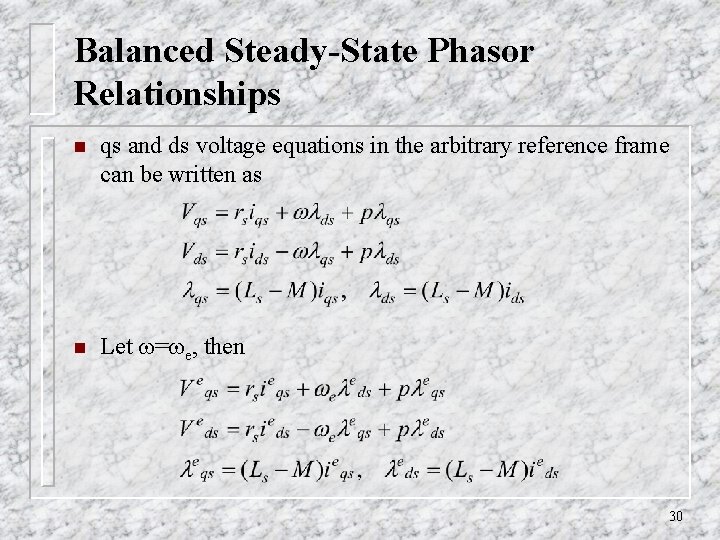
Balanced Steady-State Phasor Relationships n qs and ds voltage equations in the arbitrary reference frame can be written as n Let = e, then 30
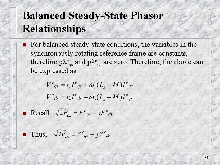
Balanced Steady-State Phasor Relationships n For balanced steady-state conditions, the variables in the synchronously rotating reference frame are constants, therefore p eqs and p eds are zero. Therefore, the above can be expressed as n Recall n Thus, 31
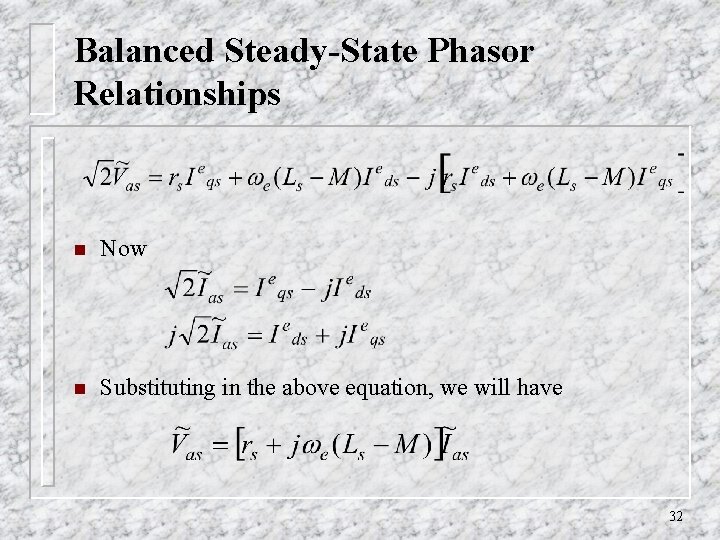
Balanced Steady-State Phasor Relationships n Now n Substituting in the above equation, we will have 32