
Lecture 17 n n AC circuits RLC circuits
- Slides: 17
Lecture 17 n n AC circuits RLC circuits Transformer Maxwell
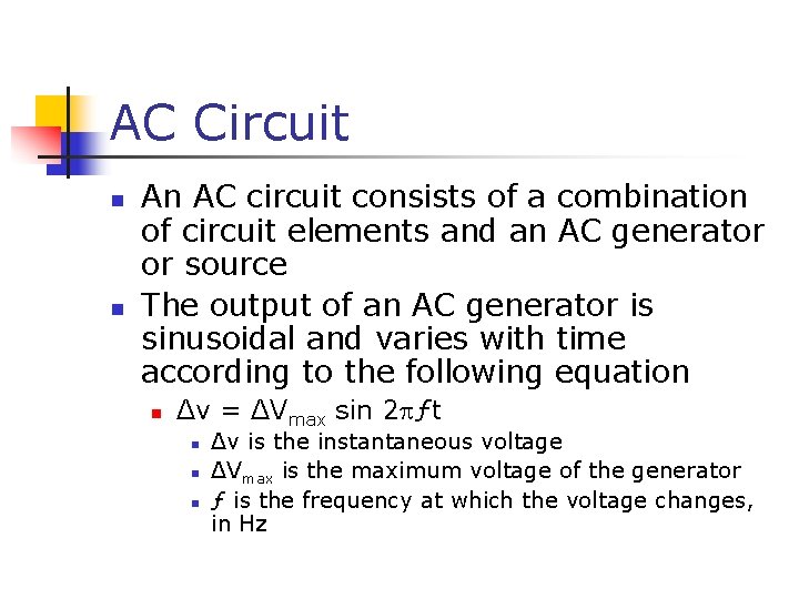
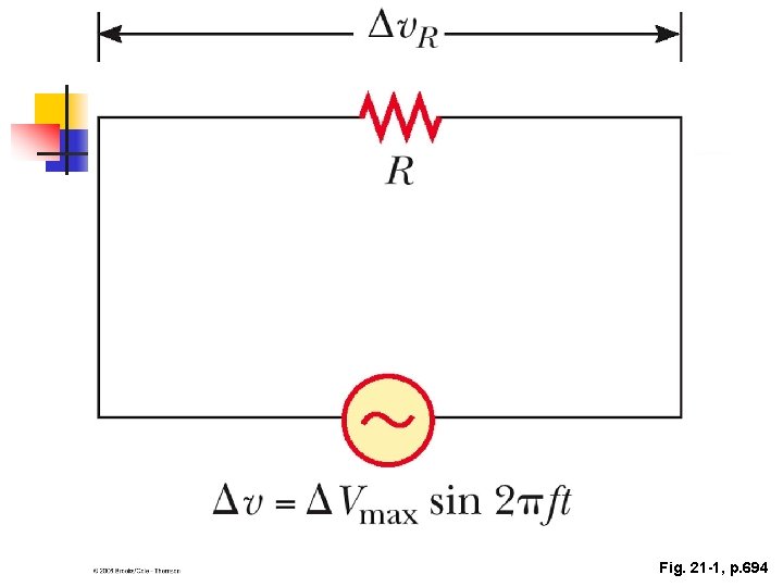
AC Circuit n n An AC circuit consists of a combination of circuit elements and an AC generator or source The output of an AC generator is sinusoidal and varies with time according to the following equation n Δv = ΔVmax sin 2 ƒt n n n Δv is the instantaneous voltage ΔVmax is the maximum voltage of the generator ƒ is the frequency at which the voltage changes, in Hz
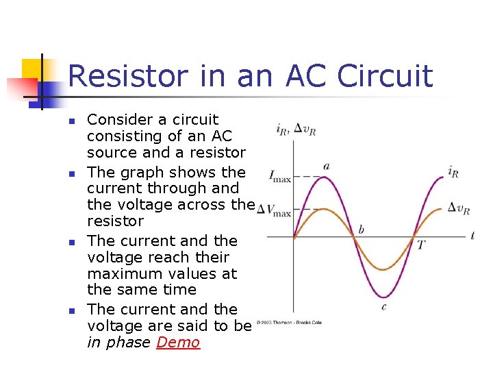
Resistor in an AC Circuit n n Consider a circuit consisting of an AC source and a resistor The graph shows the current through and the voltage across the resistor The current and the voltage reach their maximum values at the same time The current and the voltage are said to be in phase Demo
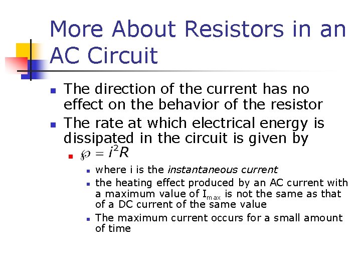
More About Resistors in an AC Circuit n n The direction of the current has no effect on the behavior of the resistor The rate at which electrical energy is dissipated in the circuit is given by n n where i is the instantaneous current the heating effect produced by an AC current with a maximum value of Imax is not the same as that of a DC current of the same value The maximum current occurs for a small amount of time
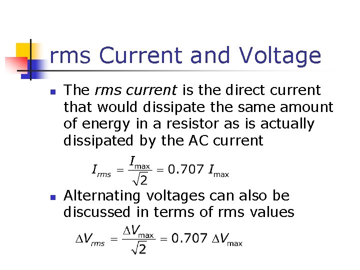
rms Current and Voltage n n The rms current is the direct current that would dissipate the same amount of energy in a resistor as is actually dissipated by the AC current Alternating voltages can also be discussed in terms of rms values
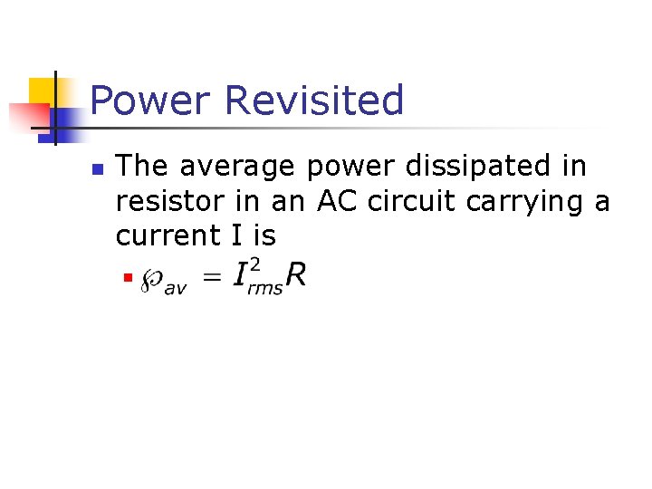
Power Revisited n The average power dissipated in resistor in an AC circuit carrying a current I is n
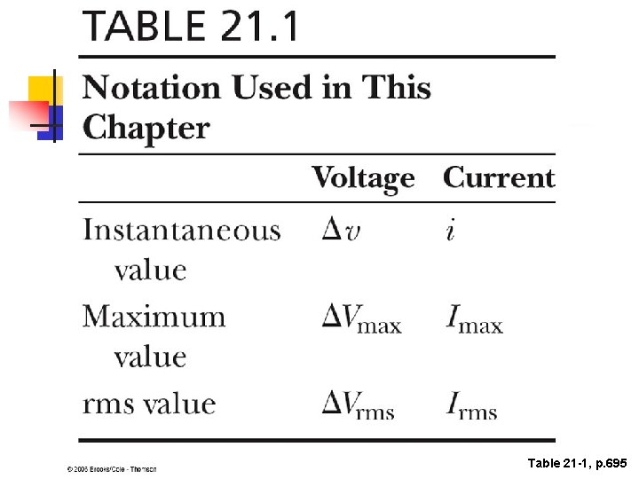
Table 21 -1, p. 695
Fig. 21 -1, p. 694
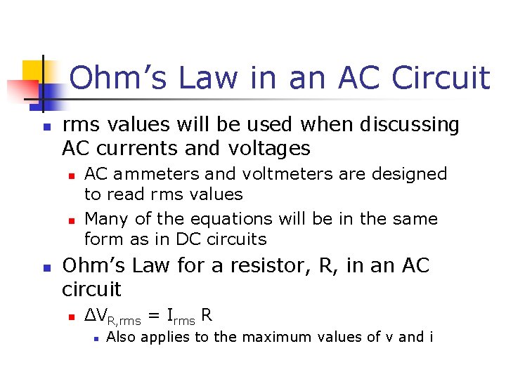
Ohm’s Law in an AC Circuit n rms values will be used when discussing AC currents and voltages n n n AC ammeters and voltmeters are designed to read rms values Many of the equations will be in the same form as in DC circuits Ohm’s Law for a resistor, R, in an AC circuit n ΔVR, rms = Irms R n Also applies to the maximum values of v and i
Capacitors in an AC Circuit n n Consider a circuit containing a capacitor and an AC source The current starts out at a large value and charges the plates of the capacitor n n There is initially no resistance to hinder the flow of the current while the plates are not charged As the charge on the plates increases, the voltage across the plates increases and the current flowing in the circuit decreases
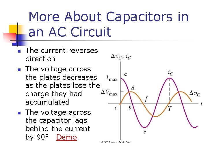
More About Capacitors in an AC Circuit n n n The current reverses direction The voltage across the plates decreases as the plates lose the charge they had accumulated The voltage across the capacitor lags behind the current by 90° Demo
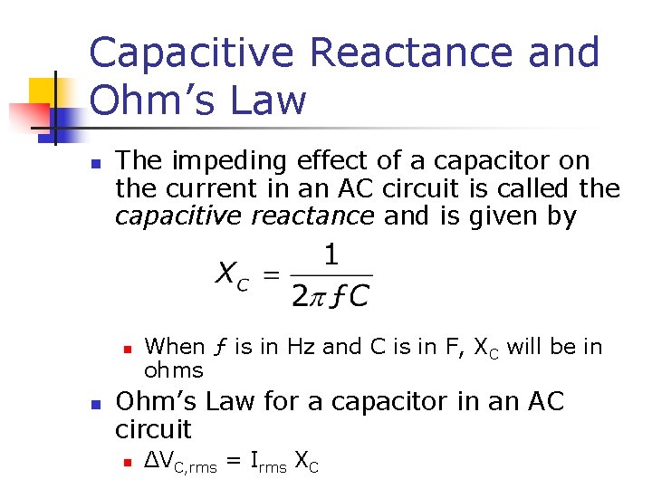
Capacitive Reactance and Ohm’s Law n The impeding effect of a capacitor on the current in an AC circuit is called the capacitive reactance and is given by n n When ƒ is in Hz and C is in F, XC will be in ohms Ohm’s Law for a capacitor in an AC circuit n ΔVC, rms = Irms XC
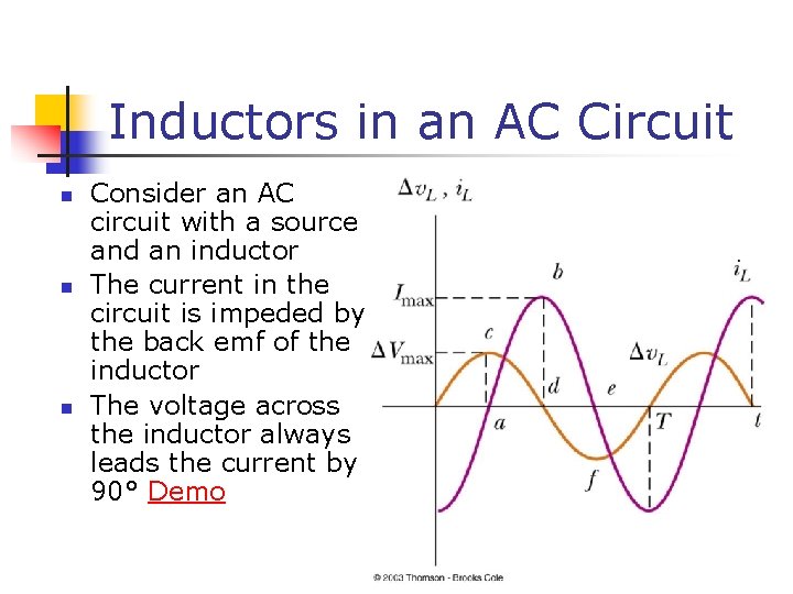
Inductors in an AC Circuit n n n Consider an AC circuit with a source and an inductor The current in the circuit is impeded by the back emf of the inductor The voltage across the inductor always leads the current by 90° Demo
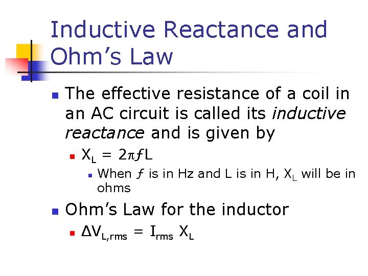
Inductive Reactance and Ohm’s Law n The effective resistance of a coil in an AC circuit is called its inductive reactance and is given by n XL = 2 ƒL n n When ƒ is in Hz and L is in H, XL will be in ohms Ohm’s Law for the inductor n ΔVL, rms = Irms XL
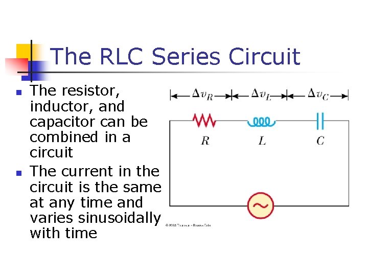
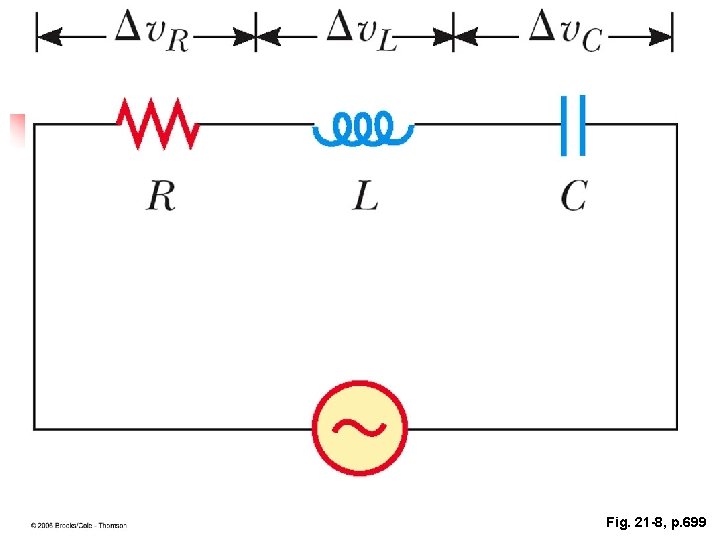
The RLC Series Circuit n n The resistor, inductor, and capacitor can be combined in a circuit The current in the circuit is the same at any time and varies sinusoidally with time
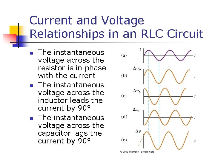
Current and Voltage Relationships in an RLC Circuit n n n The instantaneous voltage across the resistor is in phase with the current The instantaneous voltage across the inductor leads the current by 90° The instantaneous voltage across the capacitor lags the current by 90°
Fig. 21 -8, p. 699