
Lecture 14 Transistors and Operational Amplifiers ECE 205



- Slides: 21
Lecture 14 Transistors and Operational Amplifiers ECE 205 Prof. Ali Keyhani
Transistor • A semiconductor device that can be modeled with dependent sources • Transistor types: – Bipolar Junction Transistor (BJT) – Field Effect Transistor (FET) • A transistor has different operating modes with different i-v characteristics
Bipolar Junction Transistor (BJT) • BJTs are made up of alternating layers of n and p semiconductor materials joined metallurgically • Two types of BJTs: – pnp-type: Principal conduction by positive holes – npn-type: Principal conduction by negative electrons
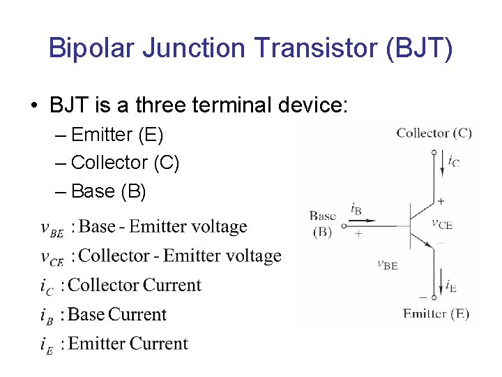
Bipolar Junction Transistor (BJT) • BJT is a three terminal device: – Emitter (E) – Collector (C) – Base (B)
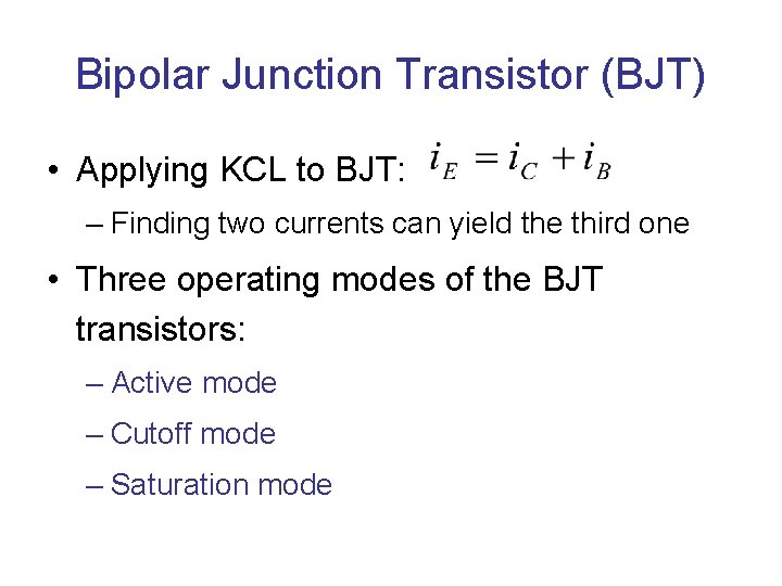
Bipolar Junction Transistor (BJT) • Applying KCL to BJT: – Finding two currents can yield the third one • Three operating modes of the BJT transistors: – Active mode – Cutoff mode – Saturation mode
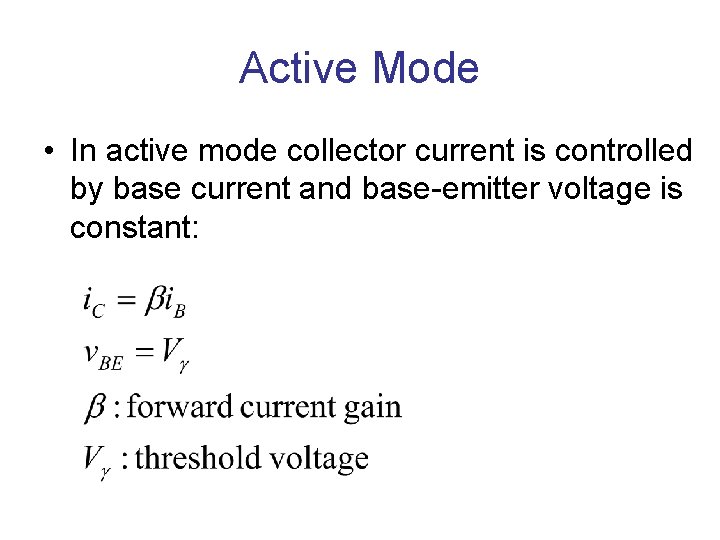
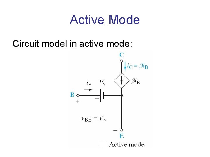
Active Mode • In active mode collector current is controlled by base current and base-emitter voltage is constant:
Active Mode Circuit model in active mode:
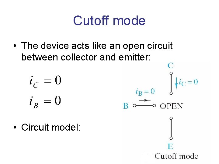
Cutoff mode • The device acts like an open circuit between collector and emitter: • Circuit model:
Saturation Mode • The device acts like a short circuit between the collector and emitter • Circuit model:
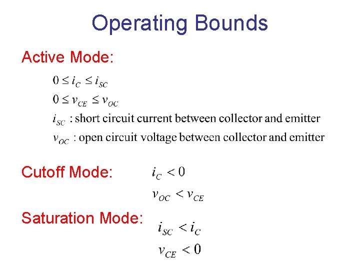
Operating Bounds Active Mode: Cutoff Mode: Saturation Mode:
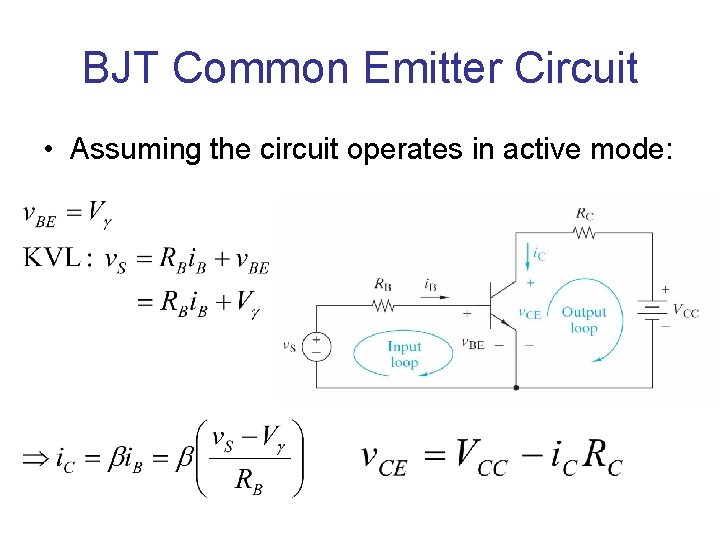
BJT Common Emitter Circuit • Assuming the circuit operates in active mode:
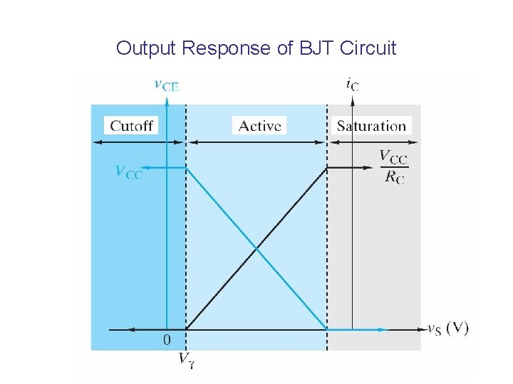
Output Response of BJT Circuit
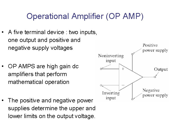
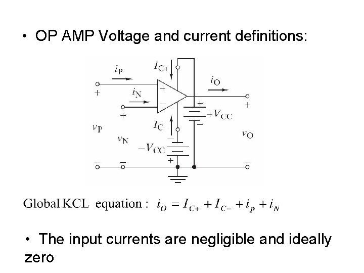
Operational Amplifier (OP AMP) • A five terminal device : two inputs, one output and positive and negative supply voltages • OP AMPS are high gain dc amplifiers that perform mathematical operation • The positive and negative power supplies determine the upper and lower limits on the output voltage.
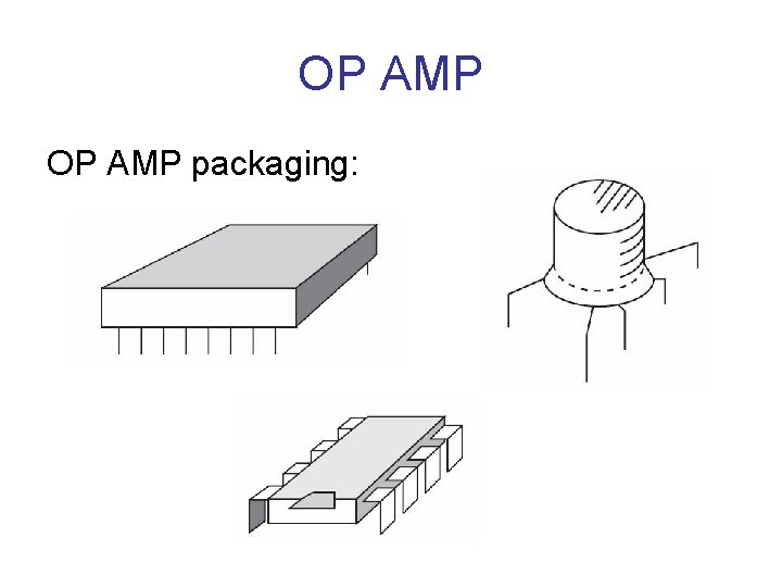
OP AMP packaging:
• OP AMP Voltage and current definitions: • The input currents are negligible and ideally zero
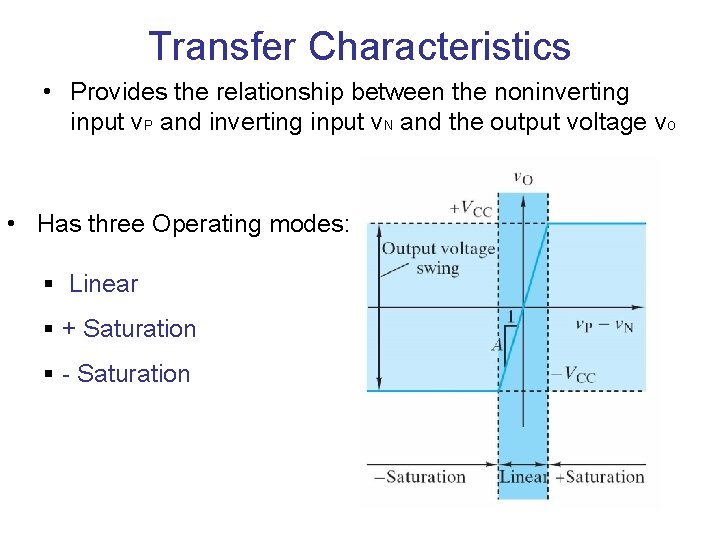
Transfer Characteristics • Provides the relationship between the noninverting input v. P and inverting input v. N and the output voltage v. O • Has three Operating modes: § Linear § + Saturation § - Saturation
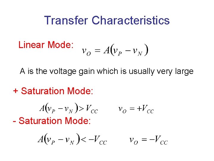
Transfer Characteristics Linear Mode: A is the voltage gain which is usually very large + Saturation Mode: - Saturation Mode:
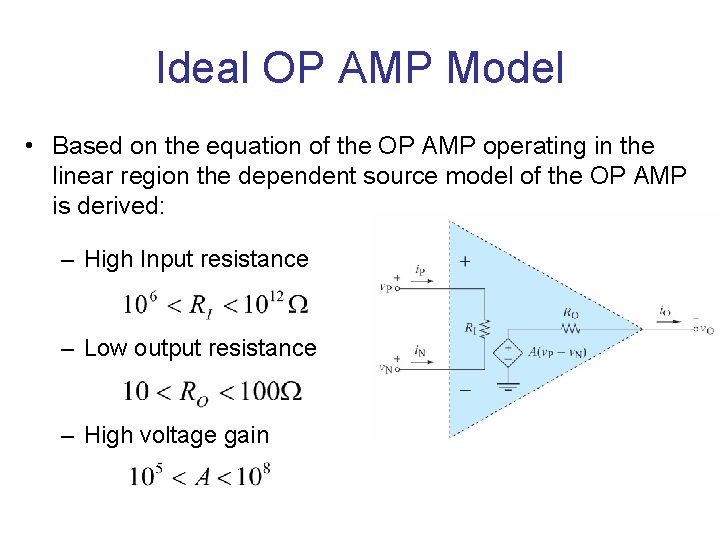
Ideal OP AMP Model • Based on the equation of the OP AMP operating in the linear region the dependent source model of the OP AMP is derived: – High Input resistance – Low output resistance – High voltage gain
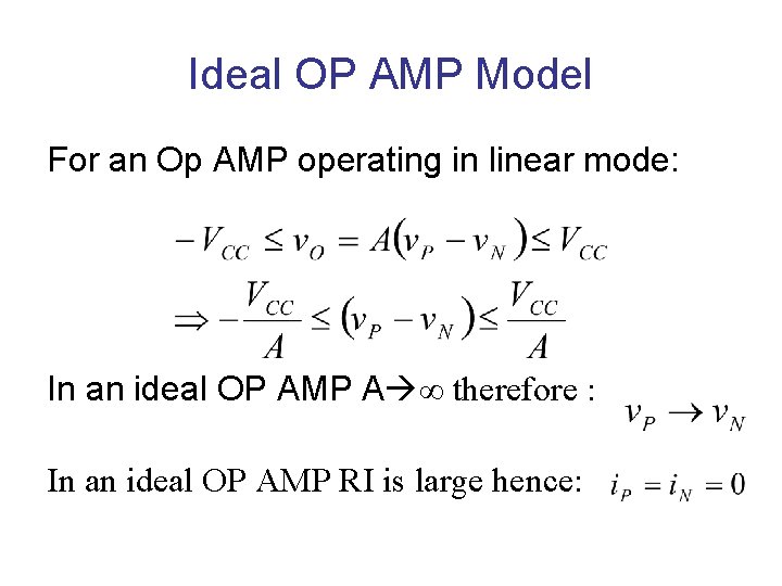
Ideal OP AMP Model For an Op AMP operating in linear mode: In an ideal OP AMP A ∞ therefore : In an ideal OP AMP RI is large hence:
Ideal OP AMP Model
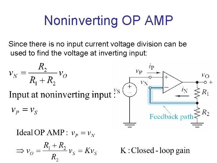
Noninverting OP AMP Since there is no input current voltage division can be used to find the voltage at inverting input: