Lecture 10 TA 101 A Engineering Graphics 2018


 Perspective view drawing See the orthographic views and sketch isometric view")
 Fig. 2. Place the lower right corner of")
 of Plan View (X) and")

 that are parallel to the bottom")


- Slides: 19
Lecture 10 TA 101 A Engineering Graphics 2018 -19 -I By Dr. Mukesh Sharma Professor DEPARTMENT OF CIVIL ENGINEERING INDIAN INSTITUTE OF TECHNOLOGY KANPUR-208016, INDIA
What kind of 3 -d Pictures are these?
As seen by eyes - Pleasing Perspective Pictures – How different are these from isometric/oblique drawing Who uses them - Architects, artists, advertising posters…
Objective is to get this picture on PP Key is convergence of rays at SP Projection line Picture Pla ne Horizon line Axis of vision Horizo n Plan e SP Groun d Plan Center of vision Ground Line e
Objective is to get this picture on PP Key is convergence of rays at SP Picture Pla ne (PP) (transpare nt) X Horizon line (HL) PP AV cv Horizo n Plane (H SP TOP VIEW SP cv HL GL Front View Any Convenient Distance SP(EYE) P) Groun d Plane Center of vision (CV) Ground Line (GL)
b B A a b ø b 1 b c d a a ø a 1 C g h e a PP f b ø ø HL SP For A, B and C examine Projection on PP HL ø SP a PP LVP RVP d RVP g h e u c f b PP VP SP HL
TOP View of point r el l l a Pa T Line view of Horizontal Plane Perspective (Plan View) SP in What view? ew Vi p o ne i l. L r Ho Object a nt SP izo ive ct e p e) L ers lan P P P V re To u t ic (P l a tic r Ve Front view of point in perspective Same way we get the VP in Front But it will be on HL What are blue lines signifying?
3 2 1, 7 5 6 4 PP VPR HL 3 2 1, 4 2, 3 1 5 4 6 7 5 6 7
2 Point (angular) Perspective view drawing See the orthographic views and sketch isometric view (Fig 1) (without hidden lines)
First draw Picture Plane (top view) Fig. 2. Place the lower right corner of Plan View on the Picture Plane and rotate it clockwise Fig. 3. The choice of 30 degrees is arbitrary, but this positioning provides a good angle for view drawing. The angle chosen should balance factors such as aesthetics and information to be conveyed.
Locate the Station Point: Measure the horizontal width (max) of Plan View (X) and double it. Extend a vertical line from the corner that touches the Picture Plane downward. At two times X locate the Station Point (Fig 4). You can have other choice of SP as well but…. .
Draw lines for the Horizon and Ground Line Fig. 5. The location of these lines are infinitely variable. The location of the Horizon Line will depend on whether you want to view the object from above eye level or below eye level. The location of the Ground Line in relation to the Horizon Line will determine how far above or below eye level the object will be viewed.
Draw 2 lines from the Station Point (SP) that are parallel to the bottom edges of the Plan View Fig 6. The lines should intersect with the Picture Plane (points a & b). Next draw vertical lines from points a & b to the Horizon Line. The point where these vertical lines intersect the Horizon Line is where the left and right vanishing points (LVP & RVP) will be located.
The last part of our preliminary layout will be to place the Side Elevation view from Fig. 1 onto the Ground Line. Project a line (orange dashed line b) from the top of the Elevation View to the vertical Line Of Sight (LS) Fig. 7. Two green dots show true height.
start projecting lines to the vanishing points. Referring to Fig. 8, draw lines from both vanishing points (LVP & RVP) to the top and bottom reference points of subject (points a & b).
To locate the vertical lines on subject, draw lines from the Station Point to corners a & b on the Plan View Fig. 9. At the point where these lines intersect the Picture Plane, draw vertical lines (orange dashed lines) downward to intersect the vanishing point projection lines.
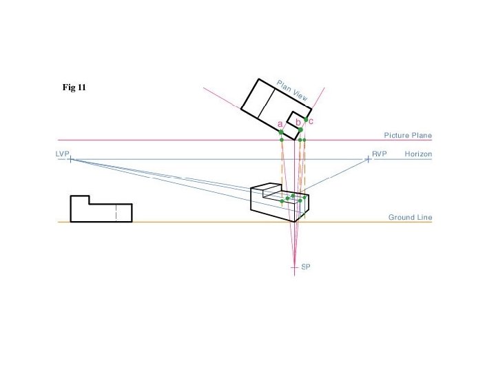
Using the same procedure as shown in Fig. 9, find the smaller features on the subject in both the Plan View and the Elevation View (a & c) in Fig. 10 and project them towards the vanishing point projection lines.
The last step is to darken the object's construction lines, and add weight to all of the exterior and outside edge lines, to increase readability Fig. 12.