Lecture 10 Switchgear Device 1 Breaker 2 Switch

Lecture #10 Switchgear Device 1. Breaker 2. Switch 3. LA 4. Relay
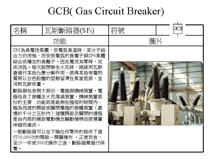

The principle of operation is similar to the air blast breakers, except that the SF 6 gas is not discharged into the atmosphere. A closed circuit completely sealed and selfcontained construction is used. The equipment consists of a compressor, a storage container, a blast valve that admits gas to the interrupting chamber, and a filter through which the exhaust gas is returned to the compressor. This is called the double pressure breaker design. 230 k. V, 15 GVA, SF 6 Double Pressure Breaker

SF 6 switchgear
 名稱 油斷路器 功能 消弧原理:用絕緣油為絕緣及消弧的介質, 啟斷電路時,電弧均發生在油面下,其週圍 的絕緣油冷卻電弧,並且使發弧區恢復絕緣, 完成消弧。 The oil in")
OCB (Oil Circuit Breaker) 名稱 油斷路器 功能 消弧原理:用絕緣油為絕緣及消弧的介質, 啟斷電路時,電弧均發生在油面下,其週圍 的絕緣油冷卻電弧,並且使發弧區恢復絕緣, 完成消弧。 The oil in OCBs serves two purposes. It insulates between the phases and the ground, and it provides the medium for the extinguishing of the arc. When electric arc is drawn under oil, the arc vaporizes the oil and creates a large bubble that surrounds the arc. The gas inside the bubble is around 80% hydrogen, which impairs ionization. The decomposition of oil into gas requires energy that comes from the heat generated by the arc. The oil surrounding the bubble conducts the heat away from the arc and thus also contributes to deionization of the arc. 符號 圖片

Figure 12 Dead Tank Oil Circuit Breaker 1 bushing 6 plunger guide 2 oil level indicator 7 arc control device 3 vent 8 resistor 4 current transformer 9 plunger bar 5 dashpot All three phases are installed in the same tank. The tank is made of steel and is grounded. This type of breaker arrangement is called the dead tank construction. The moving contact of each phase of the circuit breaker is mounted on a lift rod of insulating material. There are two breaks per phase during the breaker opening. The arc control pots are fitted over the fixed contacts. Resistors parallel to the breaker contacts may be installed alongside the arc control pots. It is customary and convenient for this type of breakers to mount current transformers in the breaker bushings.
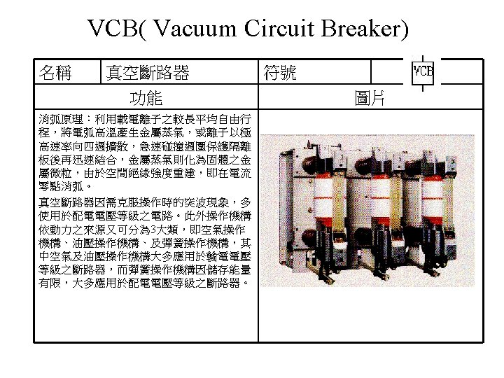

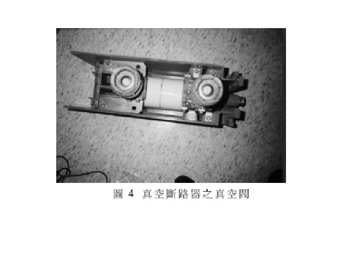
Vacuum circuit breakers are used mostly for low and medium voltages. Vacuum interrupting heads were developed for up to 36 k. V per break. For higher voltages, the interrupters are connected in series. The interrupting chambers of vacuum breakers are made of porcelain and are sealed. They cannot be open for maintenance. The contact life is expected to be about 20 years, provided the vacuum is maintained. Because of the high dielectric strength of vacuum, the interrupters are small. The gap between the contacts is about 1 cm for 15 k. V interrupters, 2 mm for 3 k. V interrupters.

Electromechanical relays

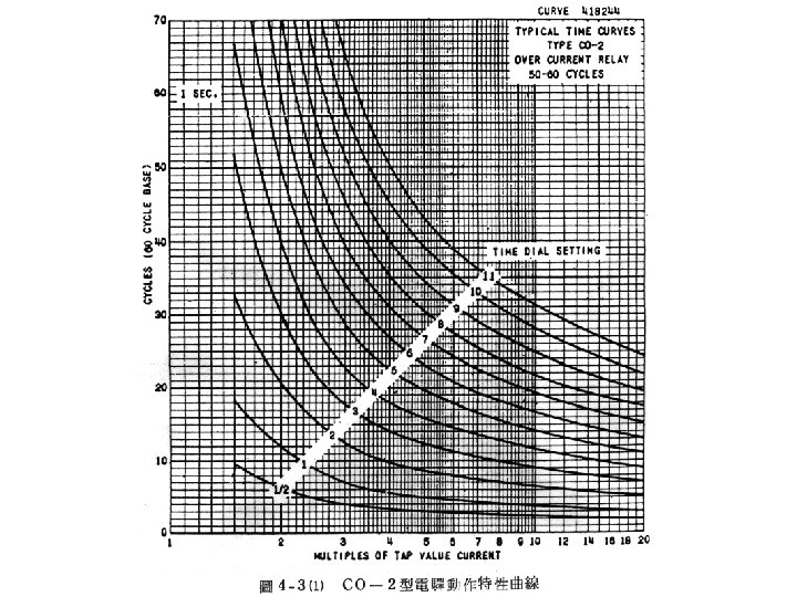
The induction disk unit operates on the same principle as induction motor. The metal disk is mounted on a shaft that can freely rotate. The current coils are fixed. They create magnetic field that induces eddy currents in the metal disk. The magnetic field of the eddy currents interacts with the magnetic field of the stationary coils and produce torque on the disk. The disk and its shaft rotate and bring the moving contact towards the fixed contact into a closed position. The motion of the shaft is opposed by a spring that returns the disk and the moving contact into the open position when the current drops below a preset value. The time to close the contact depends on the contact travel distance which is set by a time dial. The pick-up current is adjustable by selecting current taps on the current coil. The relays are normally available with three ranges of current taps: 0. 5 to 2. 0 A, 1. 5 to 6. 0 A, and 4 to 16 A. The time dial has usually positions marked from 0 to 10, where for 0 setting the contact is permanently closed.

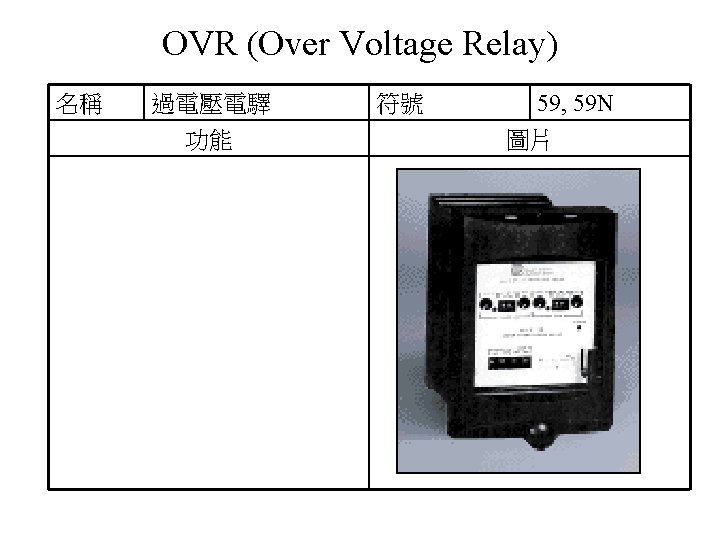

Electromechanical relays Voltage from a potential transformer is applied to the lower pole and induced into the upper poles. The upper poles induce eddy currents in the disc. The torque is produced by the interaction of the eddy currents and flux from the lower pole. Voltage settings are adjusted by voltage coil taps. The time settings are adjusted by time dial that adjusts the travel distance of the moving contact. The moving contact rotates in the horizontal plane. The return torque is provided by the spring acting on the shaft.
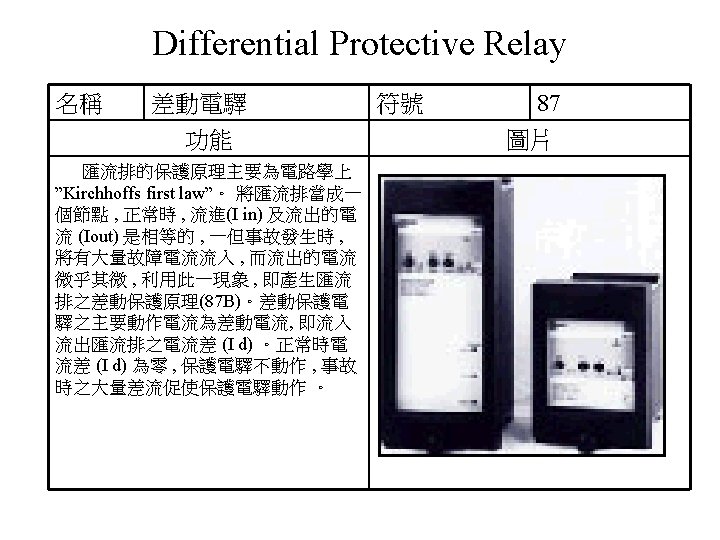

87 B High Impedance Bus Differential Relay 87 G Generator Differential Relay 87 T Transformer Differential Relay

 名稱 方向性過電流電驛 功能 符號 67 圖片 在预定的方向,交流电流给定值下 作 Solid-state")
DOC (Directional Over Current Relay) 名稱 方向性過電流電驛 功能 符號 67 圖片 在预定的方向,交流电流给定值下 作 Solid-state relays 的继电器。Use to protect transmission and distribution circuits where power can flow in either direction.
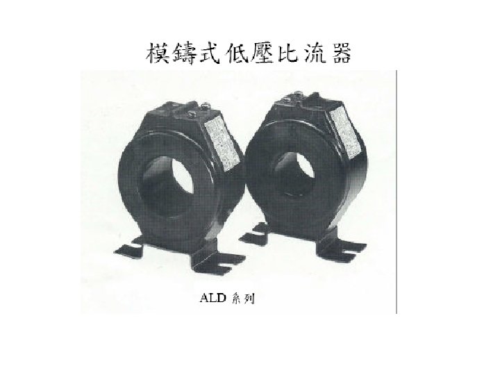
 名稱 零相電流偵測器 功能 符號 51 G 圖片")
Zero-phase current detector (ZCT) 名稱 零相電流偵測器 功能 符號 51 G 圖片
 ‧ Over/Under Frequency (81 O, 81")
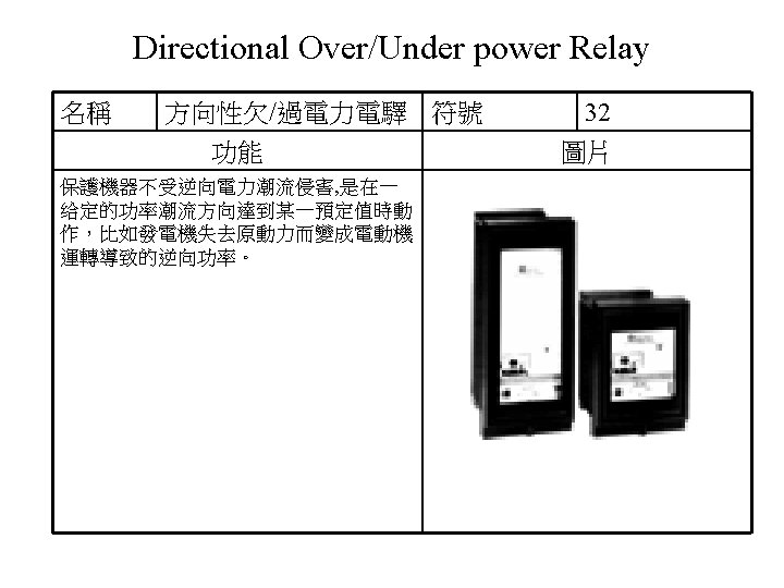
Bus Protective Features ‧ Over/Under Voltage (59, 27) ‧ Over/Under Frequency (81 O, 81 U) ‧ Directional (Forward/Reverse) Power (32) * ‧ Negative Sequence Phase Overcurrent (46) ‧ Negative Sequence Phase Overvoltage (47) ‧ Phase Overcurrent (51) * ‧ Voltage Restrained Phase Overcurrent (51 V)* ‧ Directional VAR ‧ Phase Current Imbalance (46) * Utility Protective Features ‧ Over/Under Voltage (59, 27) ‧ Over/Under Frequency (81 O, 81 U) ‧ Directional (Import/Export) Power (32) * ‧ Negative Sequence Phase Overcurrent (46) ‧ Negative Sequence Phase Overvoltage (47) ‧ Phase Overcurrent (51) * ‧ Voltage Restrained Phase Overcurrent (51 V) * ‧ Directional VAR ‧ Phase Current Imbalance (46) * ‧ Loss of Mains/Loss of Mains with Alarm ‧ Load Surge (islanding protection) Trip EGCP-3 MC Multi-unit Mains Controller Generator System Control Package delay

高壓交聯聚乙烯電力電纜 關於高壓為何需要電纜終端處裡的說明影片 http: //www. tdpowerskills. com/node/60 3 M冷縮套影片 http: //www. youtube. com/watch? v=Kz. Ex 6 Pry 2 f. Y

http: //www. elmuseum. se/images/vattenfall/Isolator_skiss. jpg

http: //www. ntnu. no/info/pressesenter/bildebase/Forskning/el_overslag_isolator_12. jpg
- Slides: 42