
Lecture 03 insulation resistance testing RVI where is




- Slides: 27
Lecture 03 絕緣電阻測試 insulation resistance testing
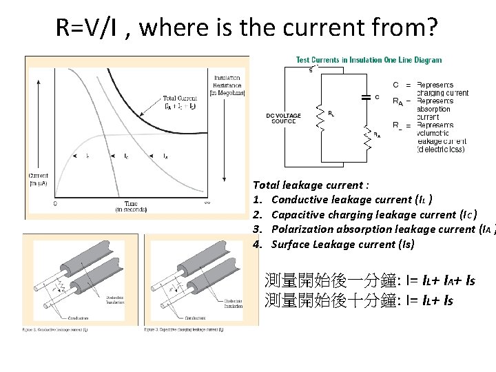
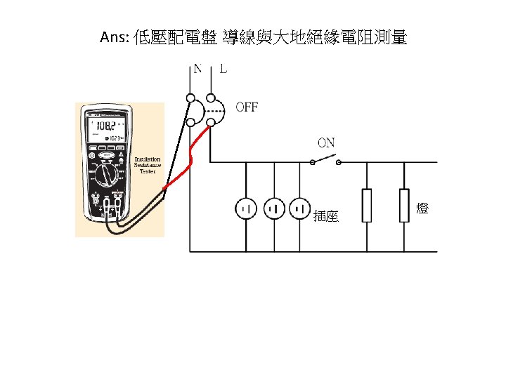
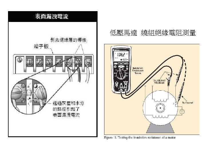
R=V/I , where is the current from? Total leakage current : 1. Conductive leakage current (IL ) 2. Capacitive charging leakage current (IC ) 3. Polarization absorption leakage current (IA ) 4. Surface Leakage current (Is) 測量開始後一分鐘: I= IL+ IA+ Is 測量開始後十分鐘: I= IL+ Is
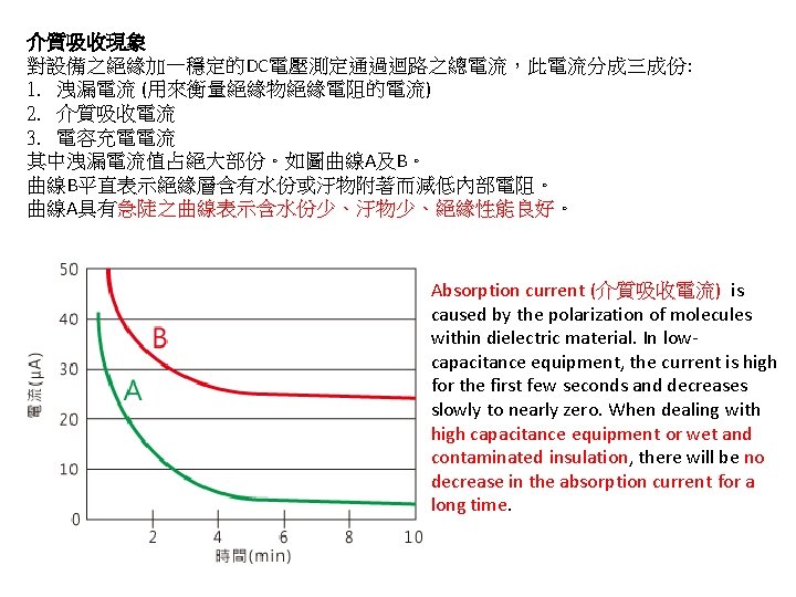
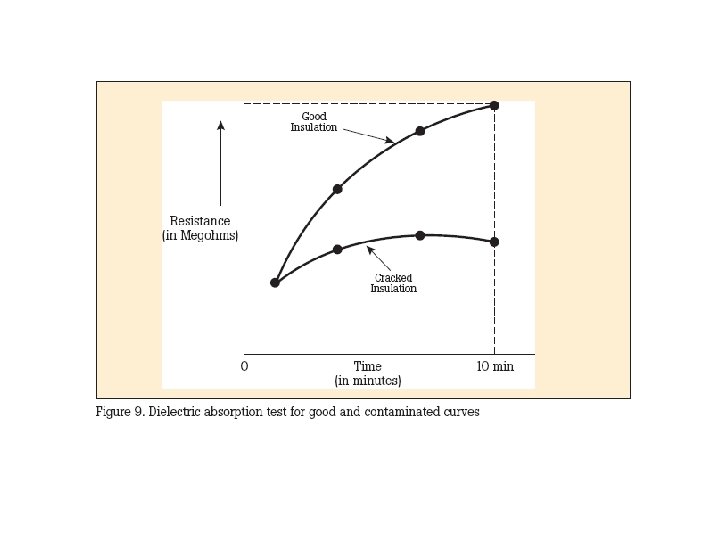
介質吸收現象 對設備之絕緣加一穩定的DC電壓測定通過迴路之總電流,此電流分成三成份: 1. 洩漏電流 (用來衡量絕緣物絕緣電阻的電流) 2. 介質吸收電流 3. 電容充電電流 其中洩漏電流值占絕大部份。如圖曲線A及B。 曲線B平直表示絕緣層含有水份或汙物附著而減低內部電阻。 曲線A具有急陡之曲線表示含水份少、汙物少、絕緣性能良好。 Absorption current (介質吸收電流) is caused by the polarization of molecules within dielectric material. In lowcapacitance equipment, the current is high for the first few seconds and decreases slowly to nearly zero. When dealing with high capacitance equipment or wet and contaminated insulation, there will be no decrease in the absorption current for a long time.
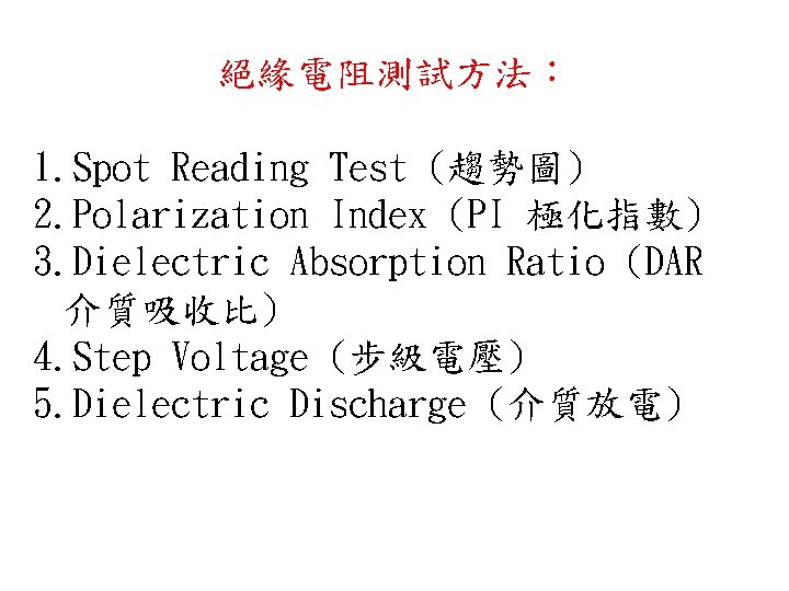
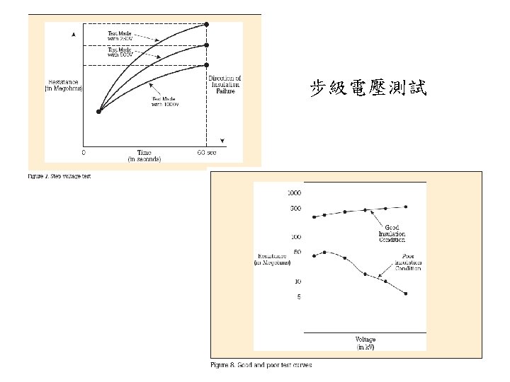
絕緣電阻測試方法: 1. Spot Reading Test (趨勢圖) 2. Polarization Index (PI 極化指數) 3. Dielectric Absorption Ratio (DAR 介質吸收比) 4. Step Voltage (步級電壓) 5. Dielectric Discharge (介質放電)
Spot Reading Test Method For this test, the megohmmeter is connected across the insulation of the windings of the machine being tested. A test voltage is applied for a fixed period of time, usually 60 seconds and a reading is taken. The spot reading test should only be carried out when the winding temperature is above the dew point (1). The operator should make a note of the winding temperature, so that it will be possible to correct the reading to a base temperature of 20 ℃. (1) Dew point temperature is the temperature at which the moisture vapor in the air condenses as a liquid. Test Duration To obtain comparable results, tests must be of the same duration. Usually the reading is taken after 60 seconds. Interpretation of Results Proper interpretation of spot reading tests requires access to records of results from previous spot reading tests. For conclusive results, only use results from tests performed at the same test voltage for the same amount of time, and under similar temperature and humidity conditions. These readings are used to plot a curve of the history of insulation resistance. A curve showing a downward trend usually indicates a loss of insulation resistance due to unfavorable conditions such as: humidity, dust accumulation, etc. A very sharp drop indicates an insulation failure. See Figure 1.
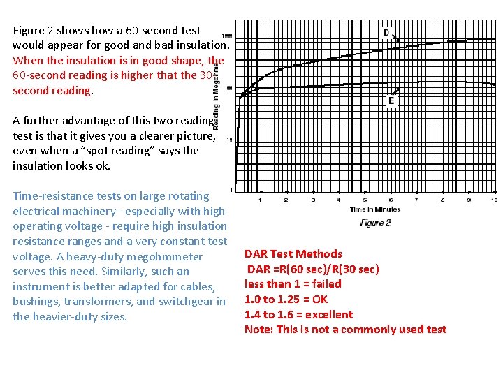
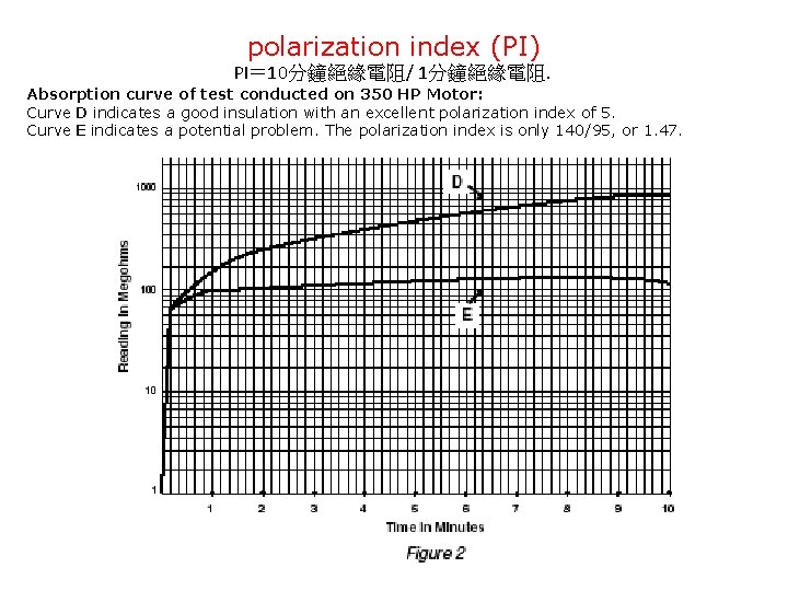
Dielectric Absorption Ratio (DAR) or Time-Resistant Tests This method is fairly independent of temperature and often can give you conclusive information without records of past tests. It is based on the absorption effect of good insulation compared to that of moist or contaminated insulation. Simply take successive readings at specific times and note the differences in readings (see curves, Figure 2). Tests by this method are sometimes referred to as absorption tests. Good insulation shows a continual increase in resistance (see curve D) over a period of time (in the order of 5 to 10 minutes). This is caused by the absorption; good insulation shows this charge effect over a time period much longer that the time required to charge the capacitance of the insulation. If the insulation contains moisture or contaminants, the absorption effect is masked by a high leakage current which stays at a fairly constant value Ð keeping the resistance reading low (R = E/I) (see curve E). The time-resistance testing is of value because it is independent of equipment size. The increase in resistance for clean and dry insulation occurs in the same manner whether a motor is large or small. You can compare several motors and establish standards for new ones, regardless of their horsepower ratings.
Figure 2 shows how a 60 -second test would appear for good and bad insulation. When the insulation is in good shape, the 60 -second reading is higher that the 30 second reading. A further advantage of this two reading test is that it gives you a clearer picture, even when a “spot reading” says the insulation looks ok. Time-resistance tests on large rotating electrical machinery - especially with high operating voltage - require high insulation resistance ranges and a very constant test voltage. A heavy-duty megohmmeter serves this need. Similarly, such an instrument is better adapted for cables, bushings, transformers, and switchgear in the heavier-duty sizes. DAR Test Methods DAR =R(60 sec)/R(30 sec) less than 1 = failed 1. 0 to 1. 25 = OK 1. 4 to 1. 6 = excellent Note: This is not a commonly used test
polarization index (PI) PI= 10分鐘絕緣電阻/ 1分鐘絕緣電阻. Absorption curve of test conducted on 350 HP Motor: Curve D indicates a good insulation with an excellent polarization index of 5. Curve E indicates a potential problem. The polarization index is only 140/95, or 1. 47.