Lect34 CE 318 N CONNECTIONS Designing Bolted Connections

Lect-3&4 CE – 318 N CONNECTIONS

Designing Bolted Connections • • • Introduction Types of Connections Bolts and Bolting Types of Bolted Joints Failure modes of bolted connections. Strength of bolts Design of bolted connection. Slip-critical connection and The slip-strength of a fully tensioned bolted connection Eccentric connections.

INTRODUCTION Ø Connections are the devises which are used to join elements of a structure together at a point such that forces can be transferred between them safely. ØConnection designed more conservatively than members because they are more complex to analyse and discrepancy between analysis and design is large. Ø In case of overloading, failure in member is preferred to failure in connection Ø Connections account for more than half the cost of structural steel work Ø Normally, a connection failure is not as ductile as that of a steel member failure. 3

INTRODUCTION Ø For achieving an economical design, it is important that connectors develop full or a little extra strength of the members, it is joining. Ø Connection failure may be avoided by adopting a higher safety factor for the joints than the members. Ø Many configurations are used force transfer in connections. Ø The configuration depends upon the type of connecting elements, nature and magnitude of the forces (and moments), available equipment, fabrication and erection considerations, cost, etc.

TYPES OF CONNECTIONS

AS PER IS CODE, BASED ON CONNECTION RIGIDITY , JOINTS ARE DEFINED AS RIGID: Ø develops the full moment capacity of connecting members and retain the original angle between the members under any joint rotation. Ø In this type of connection both the webs and flanges are connected. In this connection greater than 90% moment can be transferred with full transfer of shear and other forces Rotational movement of the joint will be very small Ø These connections are particularly used when continuity between the members of the building frame is required to provide more flexural resistance and reduce lateral deflection due to wind loads. 6

CLASSIFICATION BASED ON CONNECTION RIGIDITY SIMPLE: Ø No moment transfer is assumed between the connected parts and hence assumed as hinged (pinned). Rotational movement of the joint will be large. Ø These connections are particularly used when continuity between the members of the building frame is required to provide more flexural resistance and reduce lateral deflection due to wind loads. 7

Classification based on connection rigidity SEMI-RIGID: Ø May not have sufficient rigidity to hold the original angles between the members and develop less than the full moment capacity of the connected members. In reality all the connections will be semi-rigid only. Ø Ø These types of connections provide rigidity in between fully restrained and simple connections and approximately 20% to 90% moment compared with ideal rigid joint may be transferred. These type of connections are mostly used in practice because their performance is exceptionally well under cyclic loads and earthquakes 8

CONNECTIONS BASED ON MEANS OF FASTENING Types of connections made in steel structures based on means of fastening Riveted connections Bolted connections Welded connections 9

RIVETED CONNECTIONS A rivet is made of round ductile steel bar piece called shank with head at one end. INSTALLATION PROCESS Ø Heat rivet Ø Insert in hole Ø Hammer to produce second head Ø Cool- expands to form a tight joint

RIVETED CONNECTIONS Riveting not used now due to: The necessity of preheating the rivets prior to driving Ø Labour costs associated with large riveting crews. Ø Cost involved in careful inspection and removal of poorly installed rivets Ø High level of noise associated with driving rivets Ø NOTE: IS 800 -2007 do not discuss riveted connections

12

Black or Ordinary Bolt and Nut 13

Parts of the Bolt Assembly Grip Washer Face Nut Shank Head Thread Length • Grip is the distance from behind the bolt head to the back of the nut or washer. • It is the sum of the thicknesses of all the parts being joined exclusive of washers. • Thread length is the threaded portion of the bolt. • Bolt length is the distance from behind the bolt head to the end of 14 the bolt.

BOLTED CONNECTIONS USE Ø To make end connections Ø To fabricate built-up sections and compound sections, and Ø To form the required length of the member 15

ADVANTAGES OF BOLTED CONNECTIONS � Bolted connections offer the following advantages over riveted or welded connections: ØUse of unskilled labour and simple tools ØNoiseless and quick fabrication ØNo special equipment/process needed for installation ØFast progress of work ØAccommodates minor discrepancies in dimensions ØThe connection supports loads as soon as the bolts are tightened (in welds and rivets, cooling period is involved). � Main drawback of black bolt is the slip of the joint when subjected to loading 16

CLASSIFFICATION OF BOLT CONNECTIONS 1. Based on resultant force transferred Concentric Connection- load passes through C. G. of the section eg axially loaded tension / compression members. Eccentric Connections- when the load is away from CG of the connection eg bracket connection. Moment Resisting Connection-when joints are subjected to moments eg- beam to column connection in framed structures

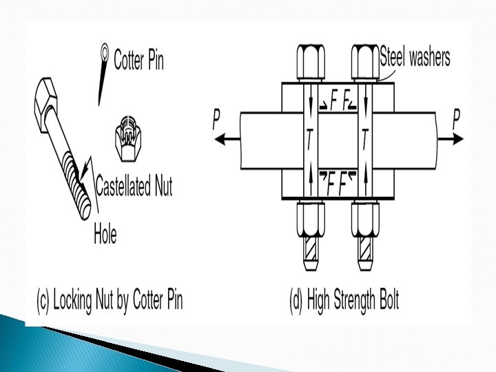
CLASSIFFICATION OF BOLT CONNECTIONS Based on METHOD OF LOAD TRANSFER: Bearing Type Bolts bear against the holes to transfer the force eg slip type connections Can fail in shear or bearing. Friction grip Type When the force is transferred by friction between the plates due to tensioning of bolts eg Slip Critical connections. Can fail when frictional force in plates exceeds the external SF F=μf T μf – slip factor T – tension in bolt

BEARING CONNECTION In a bearing-type connection, bolts are subjected to shear and the connecting / connected plates are subjected to bearing stresses :

FRICTION/ SLIP-CRITICAL BOLTED CONNECTION Slip-critical bolted connections can be installed with such a degree of tightness large tensile forces in the bolt clamp the connected plates together Applied Shear force resisted by friction

BOLTING PROCESS Ø Ø Bolting requires punching or drilling of holes. Bolt holes are usually drilled. IS: 800 allows punched holes only in materials whose yield stress (fy) does not exceed 360 MPa and where thickness does not exceed (5600/fy) mm. In cyclic loading punching avoided for plates with thickness greater than 12 mm Punch for 3 mm less and then drill. Bolt holes are made larger than the bolt diameter to facilitate erection. 21

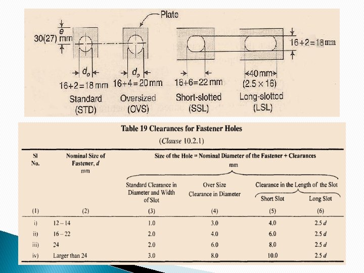
BOLTING PROCESS � � Holes may be standard size holes, oversize holes, short slotted holes, long slotted holes. Oversize holes should not exceed 1. 25 d or (d+8) mm in diameter, where d is the nominal bolt diameter in mm. Slotted hole [provided to accommodate movements) should not exceed 1. 33 d in length (for short slotted hole) and 2. 5 d in length (for long slotted hole). 22
 bolts Finished (turned) bolts High strength")
BOLT TYPES Bolts are classified as: Unfinished (black) bolts Finished (turned) bolts High strength friction grip (HSFG) bolts
 Figures in brackets are for High-strength")
Hexagonal Head Black Bolt and Nut (IS 1363) Figures in brackets are for High-strength Bolts & Nuts Black bolts are inserted in clearance holes of about 1. 5 mm to 2 mm more than the bolt diameter and then tightened through the nuts. 25
 Ø Ø")
Unfinished bolts or black bolts or C Grade bolts (IS: 1363 -1992) Ø Ø Ø These bolts are made from mild steel rods with square or hexagonal head. The shank is left unfinished i. e. rough as rolled. In structural elements to be connected holes are made larger than nominal diameter of bolts. As shanks of black bolts are unfinished, the bolts may not establish contact with structural member at entire zone of contact surface. Joints remain quite loose resulting into large deflections. These bolts are used for light structures under static loads such as roof trusses, bracings and also for temporary connections required during erections.
 Ø It")
Unfinished bolts or black bolts or C Grade bolts (IS: 1363 -1992) Ø It is not recommended for connections subjected to impact, fatique or dynamic loading like bridges. Ø Available In property class 3. 6 -12. 9. Ø Property class 4. 6 and 8. 8 are very common. Ø Ø Bolt of property class 4. 6 means, ultimate strength is 400 N/mm 2 and yield strength is 400 x 0. 6 = 240 N/mm 2. If a bolt is designated as M 16, M 20, M 24, M 30, it means shank dia of 16 mm, 20 mm, 24 mm, and 30 mm respectively. Made snug tight. (“Snug tight” is defined as the tightness that exists when all plies in a joint are in firm contact)

IS 800 stipulates that the net tensile area of bolt to be considered is the area at the root of the thread which is called the stress area or proof area. Normally for bolted joint the force is transferred through the interlocking and bearing of bolts and the joint is called bearing type joint

Finished/Turned Bolts Ø Ø These bolts are also made from mild steel, but they are formed from hexagonal rods which are finished by turning to circular shape. Tolerance available for fitting is quite small (0. 15 mm to 0. 5 mm) It needs special methods to align bolt holes before bolting. As connections is more tight, it results in to much better bearing contact between the bolts and holes. Ø Ø These bolts are used in special jobs like connecting machine parts subjected to dynamic loadings.

High strength bolts Made from bars of medium carbon steel. Normally class 8. 8 and 10. 9 are commonly used Less ductile than black bolts Material of the bolt does not have well-defined yield point. Instead of yield stress, proof load in used As per IS 800 -2007 proof load is taken as 0. 7 x ultimate tensile stress of bolt M 16, M 20, M 30, are generally used Designated like 8. 8 S, 10. 9 S, S denotes high strength bolt. Percentage elongation of these bolts at failure is approx 12%

HIGH STRENGTH BOLTS Special techniques are used for tightening the nuts to induce specified initial tension in the bolts, which caused sufficient friction between the flaying forces. These bolts with induced initial tension are called high strength friction grip (HSFG) bolts. Due to friction, the slip in the joint is eliminated hence, connection in this case is called nonslip connection or friction type connections. Coefficient of friction is called slip factor HSFG bolt provide rigid connection as no slip is involved.

As forces are transferred by friction only, bolt is not subjected to shear or bearing. there is not stress concentration in the holes. Due to high strength smaller number of bolts are used and hence material requirement of joints reduces. Since under working load, bearing does not came into play, size of holes can be larger for case of erection and to take care of lack of fit. Since the load causing fatigue will be within proof load, the nuts are prevented from loosening and hence fatigue strength of joint will be greater and better than welded a riveted joints.

TYPES OF BOLTS ØBolt Grade: Grade 4. 6 : - Ultimate strength is 400 N/mm 2 and yield strength is 400 x 0. 6 = 240 N/mm 2. Ø Bolt Types: Black, Turned & Fitted, High Strength Friction Grip Black Bolts: usually Gr. 4. 6, made snug tight, ductile and cheap, only static loads Turned & Fitted; Gr. 4. 6 to 8. 8, Close tolerance drilled holes, 0. 2% proof stress HSFG Bolts: Gr. 8. 8 to 10. 9, less ductile, excellent under dynamic/fatigue loads 33

Tensile Properties of Fasteners For grade 4. 6 bolts, nuts of grade 4 are used and for grade 8. 8, nuts of grade 8 or 10 are used. 34

TIGHTENING OF BOLTS 1. Part turn method-snug bolts- When slip resistant connections are not required, high strength bolts are tightened to a ‘snug-tight’ using an ordinary spud wrench. 2. Torque control method - When slip resistant connections are desired with HDFC bolts 3. Feeler gauge method- When slip resistant connections are desired with HDFC bolts 36

TIGHTENING OF BOLTS Feeler gauge method 37

TYPES OF JOINTS 1. Lap joint 2. Butt joint Can be designed as Bearing type or Slip Critical type connection NOTE: Section 10 of IS 800: 2007 deals with the design and detailing requirements for joints between members. 38

LAP JOINTS 39

BUTT JOINTS 40

Actions on Bolt Shear, bearing, bending P P P Lap Joint P Bearing and single plane Shear P P Bending Butt Joint P/2 P Bearing and double plane Shear P/2 P P/2
")
Terminology & Specifications IS 800 : 2007, Clause (10. 2. 4)

• Pitch, Gauge • Edge and End distance • Diameter, Area • Tacking bolts e= edge distance e’ = end distance

: - It is the center to center")
• Pitch of the Bolts (P): - It is the center to center spacing of bolts in a row, measured in the direction of Load. • Staggered Pitch (Ps): - It is the center to center distance of staggered bolts , measured in the direction of Load. • Gauge (g) : - It is the distance between two consecutive bolts of adjacent rows and is measured at right angle to the direction of load. �Edge distance is the distance at right angles to the direction of stress from the centre of a hole to the adjacent edge. �End distance is the distance in the direction of stress from the centre of a hole to the end of the element.
- shall not be less than 2. 5 d,")
1. Min Pitch. (10. 2. 2)- shall not be less than 2. 5 d, where d is the nominal diameter of the bolt. 2. (a) Max Pitch shall not be more than • 16 t or 20 mm, whichever is less, (tension members). • 12 t or 200 mm, whichever is less, (compression members) where t is the thickness of thinner plate (b) In case staggered pitch, pitch may be increased by 50% of values specified above provided gauge distance is less than 75 mm. (pitch= 1. 5*2. 5 d) 4. In case of compression member where forces are transferred through butting faces, i. e. , (butt joints), maximum pitch is to be restricted to 4. 5 d for a distance of 1. 5 times the width of plate from the butting surface.

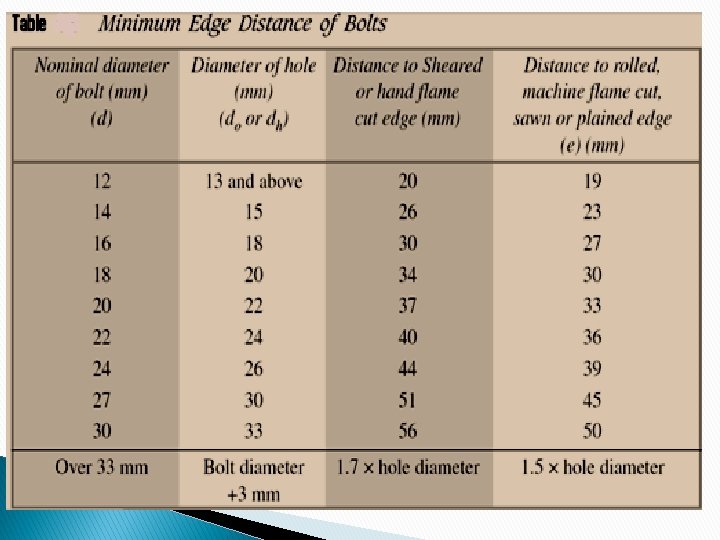
4. The gauge length ‘g’ should not be more than 100+4 t or 200 mm whichever is less in compression and tension member where t is the thickness of thinner outside plate. (10. 2. 2. 3) 5. Minimum edge and end distance shall not be (10. 2. 4) (a) Less than 1. 7 xhole diameter in case of sheared or hand flame out edges. (b) ) Less than 1. 5 xhole diameter in case of rolled, machine flame cut, sawn and planed edges. 6. Maximum edge distance (e) should not exceed (a) 12 tɛ, where ɛ = SQRT(250/fy) and t is the thickness of thinner outer plate. This recommendation does not apply to fasteners interconnecting the components of back to back tension members. (b) Where the members are exposed to corrosive environment max edge distance shall not exceed 40 mm+ 4 t, where t is the thickness of thinner connected plate.

Apart from the required bolt from the consideration of design forces, additional bolts called tacking fasteners should be provided as specified below. If the gauge length exceeds after providing fastners at maxm edge distance Tacking fastener should be provided. (i) At 32 t or 300 mm, whichever is less , if plates are not exposed to weather. (ii) At 16 t or 200 mm, whichever is less , if plates are not exposed to weather. In both cases, the distance between the lines of fasteners shall not be greater than the respective pitch 7. 8. In case of tension member made up of two flats or angles or tees of channels, tacking rivets are to be provided along the length to connect its components as specified below: (a) Not exceeding 1000 mm, if it is tension member. (b) Not exceeding 600 mm, if it is compression member.

TACKING BOLTS are additional bolts provided to satisfy the maximum pitch requirements of the steel structural members. When a member consists of two elements, which is supposed to act a single unit, then they are connected by tack bolts.

Possible Failure Modes Thus any joint may fail in any one of the following modes: �Shear failure of bolt �Bearing failure of bolt �Tensile failure of bolts The plate in a joint with bearing bolts may fail under tension due to �Shear failure of plate �Bearing failure of plate �Rupture/ Tensile failure of plate �Shear block Failure 51

Possible Failure Modes 52

Block shear
 54")
Bearing Failure of Bolt Photo by P. S. Green (Copyright© AISC) 54

Tension Failure of Bolts Photo by J. A. Swanson and R. Leon of Georgia Institute of Technology © AISC 55

Bearing Failure of Plates Photo by J. A. Swanson and R. Leon of Georgia Institute of Technology© AISC 56

Tension failure Limit state Photo by J. A. Swanson and R. Leon of Georgia Institute of Technology© AISC 57

Typical Block Shear Failure 58
- Slides: 58