Lec 6 7 FLOW IN PIPES Dr Zainab

Lec 6, 7 FLOW IN PIPES Dr. Zainab Talib Al-Sharify Email: zainab_talib 2009@yahoo. com

Summary Ø Lecture 4 Chapter 9 § Flow in closed pipes § Establishment of flow in pipes § Length of flow establishment § Steady uniform flow in circular pipes § Laminar and turbulent flow in circular pipes § Analytical approach (Moody chart, Darcy law) § Some examples § Tutorial questions

Chapter 9: Fluid flow in pipes Flow in closed pipes

Measuring Flow in Pipes and Closed Conduits The Division recommends direct measurements in pipes or closed conduits using flowmeters due to their high degree of accuracy. Making the best flowmeter choice can be challenging because of the large variety of meters available. Long-term maintenance and operating costs are critical factors to consider during selection. Most flowmeters that perform unsatisfactorily can usually be traced to improper selection. The most efficient meters have fewer moving parts and have minimal impacts on line pressures, which are important factors in silty water conditions. A flowmeter that has a totalizer capable of recording continuous volume over time is required. https: //www. waterboards. ca. gov/waterrights/water_issues/programs/measurement_regulation/docs/water_measurement/conduit. pdf

Some considerations for selecting a flowmeter are listed below � Totalizers: are used to measure the total quantity of water over time. Totalizers can be installed separately or as part of a flowmeter unit. They are particularly useful when pumping rates vary over time. � Water quality: some flowmeters are limited to either clean or silty waters. If the water you are pumping is loaded with particulates, be sure to choose a meter suitable for dirty water like a Doppler or mag meter. � Maintenance: excessive maintenance costs result with a poor match between the instrument and the application. With a wide range of prices for flowmeters, try to choose a meter with the lowest with moving parts. Installing a filter ahead of the meter will help minimize fouling and wear but could cause a pressure loss which equates to greater power consumption.

� Rangeability: is a flowmeter’s ability to cover a range of flow rates, defined as the ratio of minimum to maximum flow rates. For example, a meter with minimum flow of 100 gal/min and maximum flow of 500 gal/min has a turndown ratio of 5. Select a meter with the lowest ratio that is suitable for your operating flow range. Rangeability is often referred to as the turndown ratio. � Pressure loss: the presence of a flowmeter can cause increased pressure losses which increases pumping/energy costs. Consider selecting a meter that has minimal impacts to pressure loss in the pipe system. � Straight pipe requirements: one of the most common installation mistakes is not allowing sufficient upstream and downstream straight-run piping for the flowmeter. A common problem is when the upstream unobstructed, straight pipe length recommendation cannot be met. Check with the flowmeter manufacturer since each meter has a recommended straight pipe-length upstream of the flowmeter.

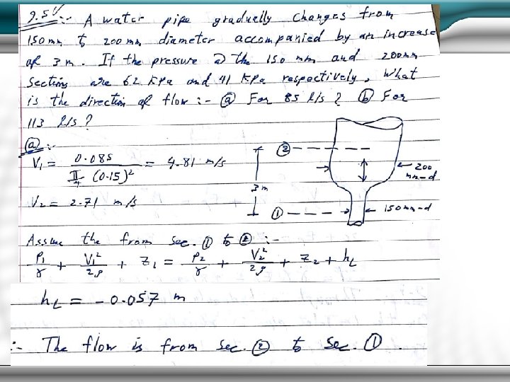
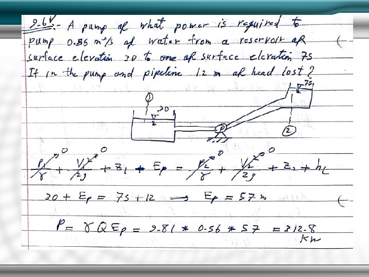
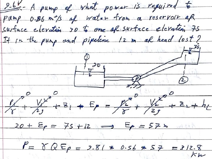
Fundamental Equations- Incompressible flow Bernoulli equation:

Summary head loss If you want more information See the following videos : https: //www. youtube. com/watch? v=w. JAc. DVqyk. Z 8 https: //www. youtube. com/watch? v=mb 8 cl. Qdvrvo
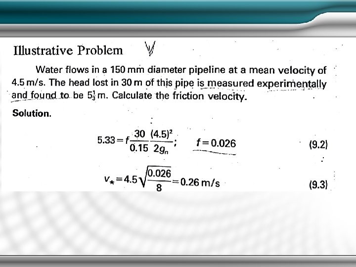

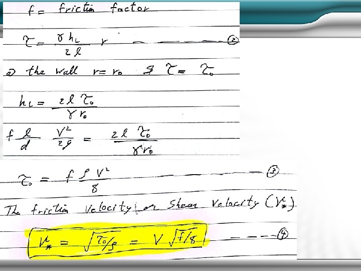
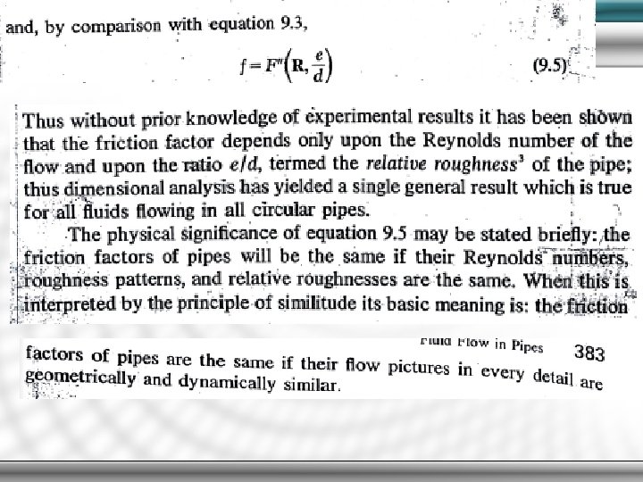
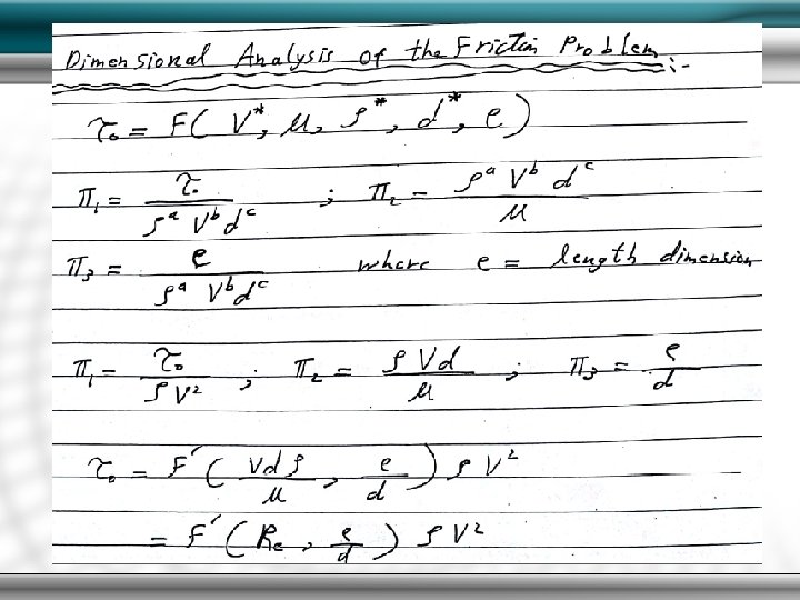
Establishment of flow in pipes Dimensional analysis of the friction problem- incompressible flow

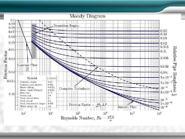
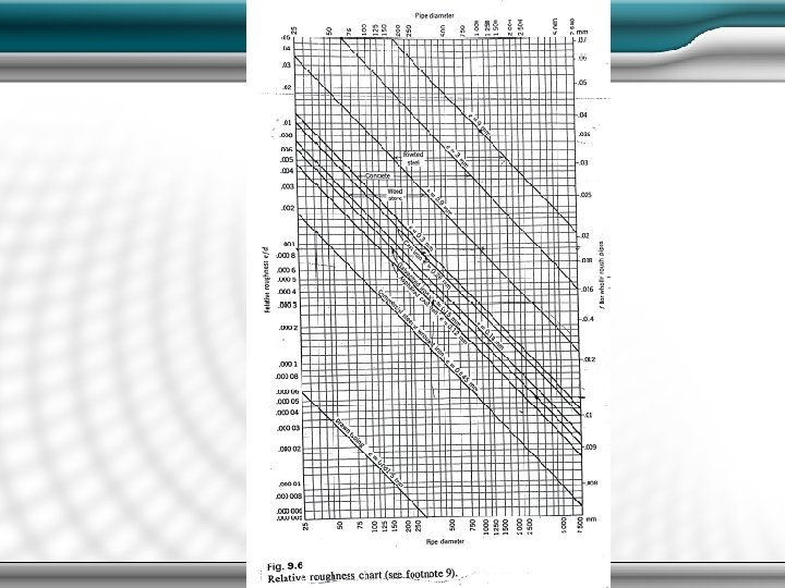
Moody diagram or stanton diagram
 is used to")
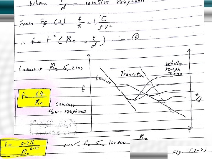
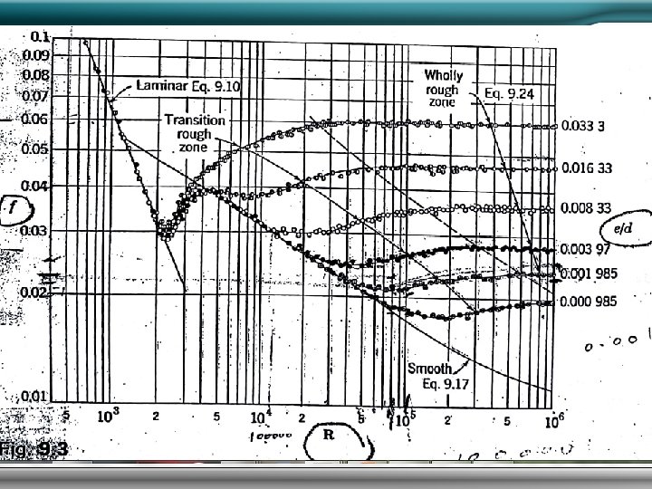
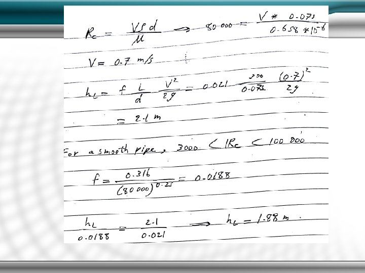
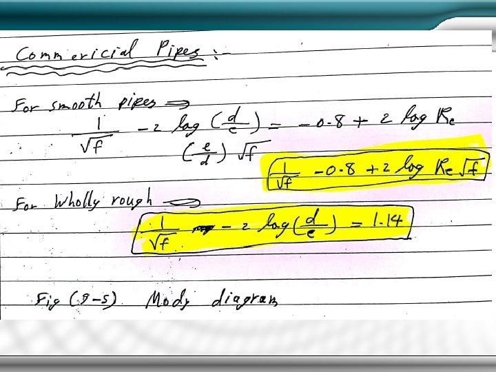
A Moody chart and commercial pipes A Moody chart (see below) is used to determine the turbulent flow friction factor from the Reynolds number and the relative roughness of the pipe. If the flow is laminar then the fricton factor is 64/Re. Various typical values of hydraulic roughness (ε) In the moody chart above (ε /D ) is identified with both numerator and denominator in metres (for consistency with all other equations on this page. It is probably more convenient to express both in (mm). i. e a 50 mm cast iron pipe (ε mm; /Dmm ) would simply be (0, 203 /50 ).

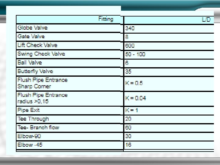
Typical Values of L/D for Fittings The losses through fittings are generally evaluated by obtaining K = f. T(L/D) Table of pipe friction values for clean pipe in region of complete turbulence
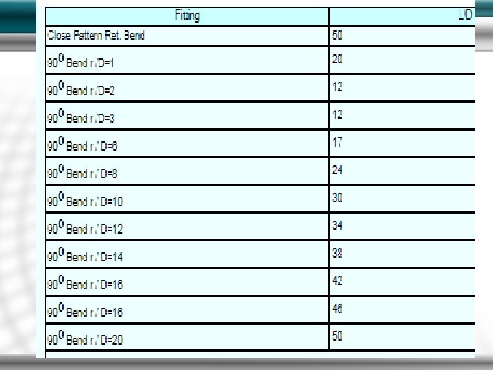

The K 180 value for a 180 o bend may be derived from the equivalent K 90 which is calculated from the above tables using the equation For laminar fluids with low Re numbers ( "<" 500) the K values obtained using the above are probably very innaccurate. The table below illustrates how this affects the K values

ues for Sudden Expansion-Contraction & Orifice The losses through these fitting are generally evaluated by first obtaining β = d 2 / d 1 Important Note: the resulting K values as tabled below are based on the flow velocity in the larger pipe if the flow velocity in the small pipe is used to evaluate the head loss then the K values tabled below should be multiplied by ( β ) 4 = (d 2 / d 1) 4 http: //www. roymech. co. uk/Related/Fluids_Pipe. html
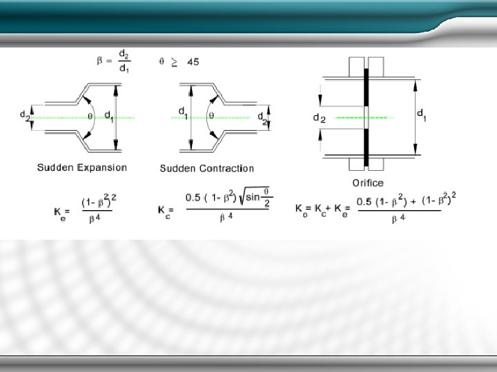

Table of Ke, Kc & KO against β = d 2 / d 1 Reasonable Velocities of fluid in Pipes

References, for this lecture only 1. Venturi Meters Constructed with Pipe Fittings, Pap-1050, USBR 2. Implementation of Magnetic Meters for Irrigation Volumetric Measurement, ITRC Paper No. P 12 -006 3. List of Flowmeter Vendors https: //www. youtube. com/watch? v=5 BH 4 i. STv 16 Y https: //www. youtube. com/watch? v=n. Ply. Wie. Nvy. I https: //www. khanacademy. org/science/physics/fluid-dynamics/v/fluids-part-7 http: //eleceng. dit. ie/gavin/Instrument/Fluid%20 Flow. pdf

References

Dr. Zainab Talib Al-Sharify Thank you!
- Slides: 43