Leaning Tower of Pisa History Construction Process Causes


 • Formed by a double series of small-diameter piles •")


 Placement of piles Ø Small diameter piles used. Ø Piles")


 • Sequence of Construction: ii. The spoil is removed by")

 Ø Piles are all connected by RC capping beam Ø")


- Slides: 35
Leaning Tower of Pisa • • • History Construction Process Causes of Lean Underpinning by excavation Implications
History • Built to show the rest of the world the wealth of the city of Pisa, now Italy • Architect unknown • Cathedral & Baptistery meant to be centerpieces • Tower was really just a ancillary structure to complement the site
Construction process • Height – 60 m from ground • Weight – 14, 500 tons • Features – 8 th order circular bell tower • Foundation – Circular strip foundation 19. 6 m diameter • Tilt – 5. 5 o from vertical
Underpinning by extraction • Reduce the inclination of the Tower by up to half a degree to 5. 5 o • To move the Tower back to a less stressful position, the north side of the tower needs to sink • Induce subsidence beneath north side of the foundation without touching the structure of the Tower
Anchoring • Suspending cables have been loosely fixed to the tower to support it as the soil extraction goes on • Pull back on the tower if it started leaning
Soil extraction • simultaneous reduction of both foundation overturning moment and masonry overstressing • Soil extraction: involves controlled removal of small volumes of soil from the sandy silt formation of Horizon A beneath the north side of the foundation by means of an inclined drill as shown in Fig.
Drilling Tubes at North Side
Drill Rig details
Conclusion • Tilt brought back to 5 o and stabilized • So far the soil extraction has been so successful that the cables have not been needed • Durability of about 30 years
Evaluation of Extraction 4 factors: • • Appearance Cost Feasibility Long–term results
Appearance • The look of the tower would not be affected by the changes since they are completely underground. • Periodic Soil Removal would decrease the tilt by about 10%, but this will not be noticed by the naked eye.
Cost • Maintenance will certainly be expensive. • The Soil Removal now being completed has cost about US$4 million. This cost will be much lower the second time around and the bill would not have to be paid until work is needed, which is likely to be decades from now.
Feasibility • Soil removal has proved itself as being a feasible technique in preserving the tower, so the Periodic Soil Removal plan would also be feasible as long as the operation is carried out in the same manner.
Long-term results • Periodic Soil Removal would give the best long-term results. Each time soil needs to be removed, the lean of the tower could be altered to the north, south, east or west with millimeter accuracy. Therefore the ideal position for the tower can always be achieved for as long as the tower stands.
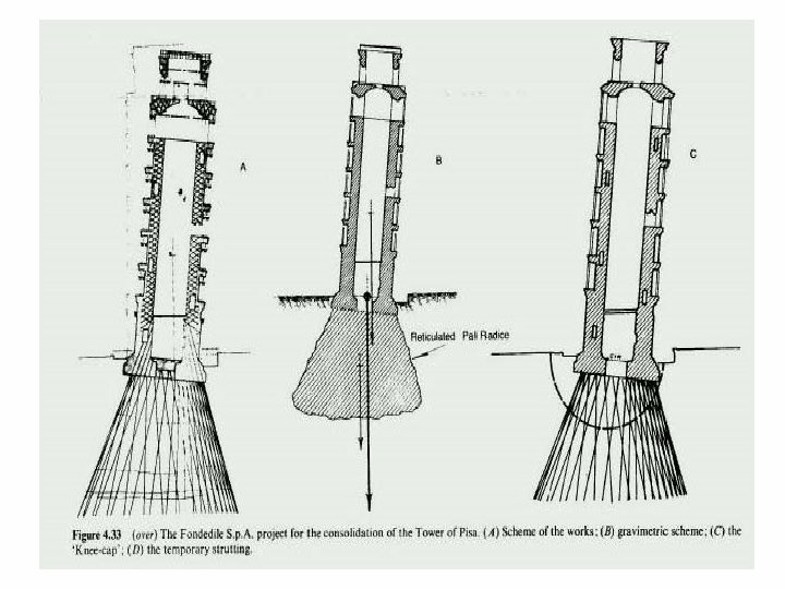
Recommended Method Pali Radice Refer to article
Pali Radice (Root Piles) • Formed by a double series of small-diameter piles • Piles tied to Capping Beam • Capping Beam connected to existing structure.
Justification ØPiles are constructed underneath the foundation of a structure, bonded together, and thus achieving a direct connection between the piles and the existing foundation. Ø The piles are not visible in position and therefore do not cause and alteration to the appearance of the existing structure.
Justification con’t Ø Pali Radice is essentially a frictional piles Ø Even when the piles are formed, the structure continues to rest on its old foundation. Ø It does not supercede the existing foundation. All its function is complementary and only when necessary does it contribute to the foundation. Ø The bearing capacity of the piles are added to that of the existing soil, thereby increasing the Factor of Safety.
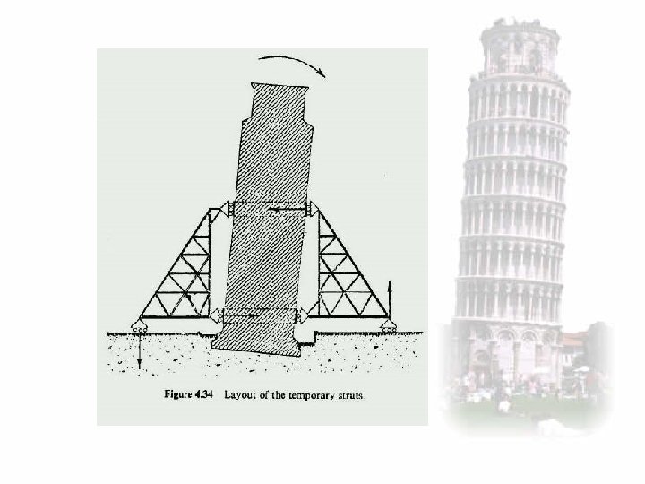
Temporary Works Ø This system of underpinning does not require excavation and/ or shoring (which is not true pertaining to the case study on Leaning Tower of Pisa, due to precautionary reasons), thereby preserving the equilibrium of the structure during underpinning work.
Raking shores • Load from the shores is transferred to the ground by means of grillages • Soleplates should be kept clear of the edge of the underpinning
Raking Shores
Construction Sequence : (1) Placement of piles Ø Small diameter piles used. Ø Piles are constructed in stages around the building.
Root Piles Pisa Tower Plan View
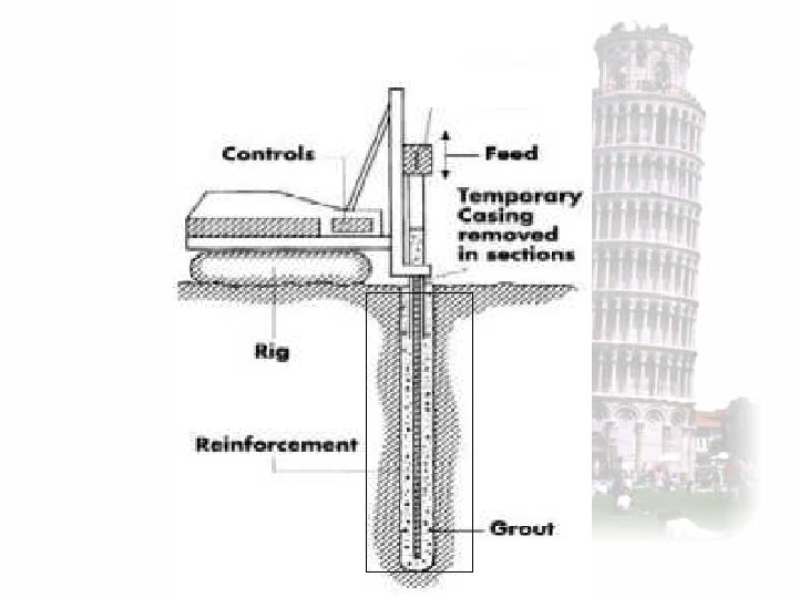
Const Sequence con’t i. Drilling commenced by a rotating casing, which is progressively introduced into the subsoil. Ø no vibration involved
Const Sequence con’t The special cutting bits are fixed on the edge of the casing, thus enabling piles to be constructed through virtually any buried obstructions.
Pali Radice (root piles) • Sequence of Construction: ii. The spoil is removed by flushing water or bentonite mud introduced from the top through a rotating swivel. iii. Once the drilling has been taken to the designed depth, the reinforcement: a single bar; a cage or a tube with a larger diameter, is placed.
Const Sequence con’t iii. The grout is then placed by tremie pipe, whereby the mix is to be a high-strength grout. (ie: around 600 to 800 kg of cement per m 3 of sieved sand. iv. Once the casing has been filled, it is gradually extracted. v. At the same time, compressed air introduced from the top pushes the mix outside the pipe against the borehole.
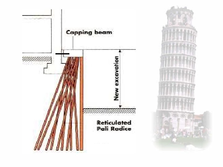
Construction Sequence (Capping Beam) Ø Piles are all connected by RC capping beam Ø to provide connection to the existing structure
Plan View
Reticulated Pali Radice • Three dimensional lattice soil/pile structure • Resist compressive as well as tensile shear forces • System is based on the interaction between pile and soil • Provide a kind of ‘knot’ effect
video