
Leak Detection Tutorial Paul Cruikshank Giuseppe Bregliozzi CERN
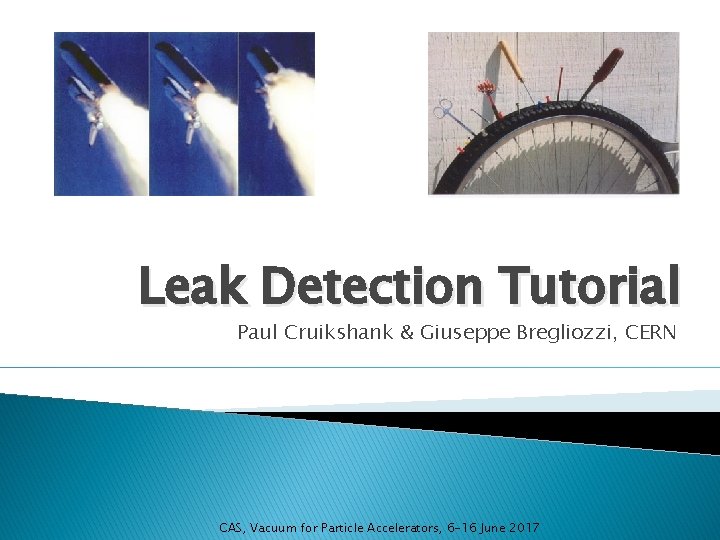
Leak Detection Tutorial Paul Cruikshank & Giuseppe Bregliozzi, CERN CAS, Vacuum for Particle Accelerators, 6 -16 June 2017
Leak Detection – Today’s Agenda ◦ 14: 30 ‘Introduction to leak detection’ - part 1 ◦ 15: 00 Practical 1 – Working with MS leak detector � 2 groups of 8 students rotating between stands ◦ 15: 40 ‘Introduction to leak detection’ - part 2 ◦ 16: 00 Practical 2 - Leak testing of manifolds ◦ ◦ ◦ � 3 groups of students on 3 similar stands 16: 30 Break 17: 00 Discussion on practicals 17: 10 Leaks in NEG coated systems with demonstration 17: 50 Leak exercises End of tutorial CAS Vacuum, June 2017 2
Leak Detection – Part 1 ◦ Leak units, Variation f(T, p, gas species) ◦ Common methods & their limits: �Over pressure �Under vacuum ◦ Leak detection with mass spec leak detector CAS Vacuum, June 2017 3
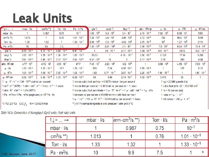
Leak Units � Insert table of equivalent units atm· CAS Vacuum, June 2017 4
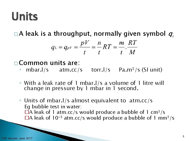
Units �A leak is a throughput, normally given symbol q. L � Common ◦ mbar. l/s units are: atm. cc/s torr. l/s Pa. m 3/s (SI unit) ◦ With a leak rate of 1 mbar. l/s a volume of 1 litre will change in pressure by 1 mbar in 1 second. ◦ Units of mbar. l/s almost equivalent to atm. cc/s Eg bubble test in water: �A leak of 1 atm. cc/s would produce a bubble of 1 cm 3/s �A leak of 10 -3 atm. cc/s would produce a bubble of 1 mm 3/s CAS Vacuum, June 2017 5
Units � …. flux through a leak will be different depending on the prevailing conditions (temperature, pressure, gas type) � Unless otherwise stated, a ‘standard helium leak rate’ in mbar. l/s implies: ◦ ◦ Helium as tracer gas, Under vacuum test, Helium at 1 barabs and 100% concentration System at 20 °C. � Any CAS Vacuum, June 2017 other conditions must be stated 6
Leak flux… � Variation of pressure � Variation of temperature � Variation of gas type CAS Vacuum, June 2017 7
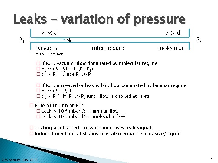
Leaks – variation of pressure λ≪d P 1 q. L viscous turb λ>d laminar intermediate molecular P 2 � If P 2 is vacuum, flow dominated by molecular regime � q. L ∝ (P 1 -P 2) = C (P 1 -P 2) � q. L ∝ P 1 since P 1 ≫ P 2 � If P 2 is increased or leak is big, flow dominated by laminar regime � q. L ∝ (P 12 -P 22) � q. L ∝ P 12 if P 1 ≫ P 2 (until flow is choked at inlet) � Rule of thumb at RT: � Leak > 10 -4 mbarl/s – laminar flow � Leak < 10 -5 mbar. l/s – molecular flow � Testing at elevated pressure increases leak signal � Induced mechanical strains may also enhance leak size/signal CAS Vacuum, June 2017 8
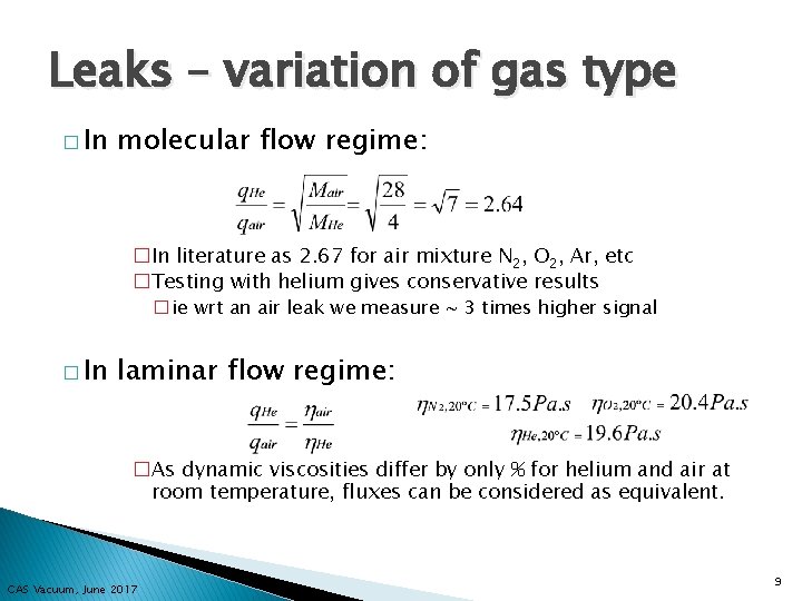
Leaks – variation of gas type � In molecular flow regime: �In literature as 2. 67 for air mixture N 2, O 2, Ar, etc �Testing with helium gives conservative results �ie wrt an air leak we measure ~ 3 times higher signal � In laminar flow regime: �As dynamic viscosities differ by only % for helium and air at room temperature, fluxes can be considered as equivalent. CAS Vacuum, June 2017 9
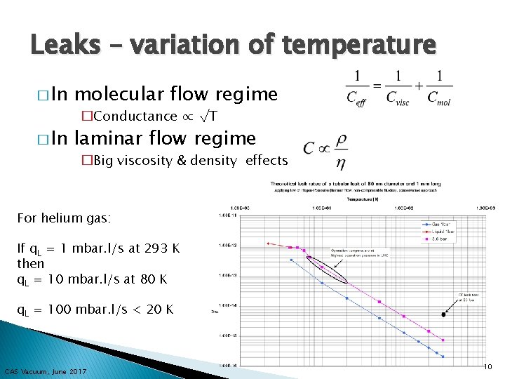
Leaks – variation of temperature � In molecular flow regime � In laminar flow regime �Conductance ∝ √T �Big viscosity & density effects For helium gas: If q. L = 1 mbar. l/s at 293 K then q. L = 10 mbar. l/s at 80 K q. L = 100 mbar. l/s < 20 K CAS Vacuum, June 2017 10
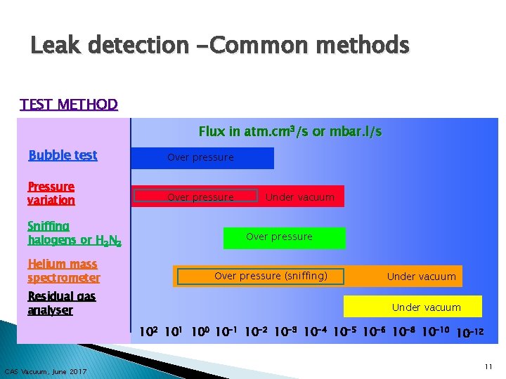
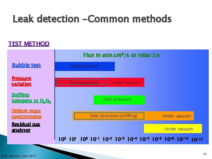
Leak detection -Common methods TEST METHOD Flux in atm. cm 3/s or mbar. l/s Bubble test Over pressure Pressure variation Over pressure Sniffing halogens or H 2 N 2 Helium mass spectrometer Residual gas analyser Under vacuum Over pressure (sniffing) Under vacuum 102 101 100 10 -1 10 -2 10 -3 10 -4 10 -5 10 -6 10 -8 10 -10 10 -12 CAS Vacuum, June 2017 11
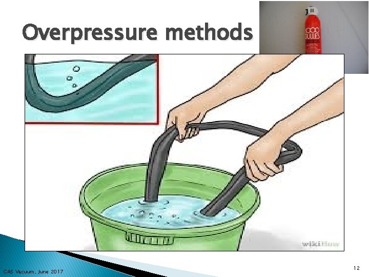
Overpressure methods (1) � Bubble test/Soap spray: ◦ Milles Bulles (Thousand Bubbles!) ◦ Visual test for big leaks ◦ Immersion (eg bicycle tyre) not practical for some applications ◦ System must be able to support overpressure �Above 1. 5 bar (absolute) safety rules apply ◦ Can be employed on complex pipe work �Remember 1 mbar. l/s ~ 1 atm. cm 3/s �Pressurised gas is emerging to make bubbles at 1 atm, so 1 bubble of 1 mm 3/s would be 10 -3 atm. cm 3/s �Detection limit ~ 10 -4 mbar. l/s CAS Vacuum, June 2017 12
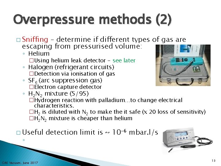
Overpressure methods (2) � Sniffing – determine if different types of gas are escaping from pressurised volume: ◦ Helium �Using helium leak detector - see later ◦ Halogen (refrigerant circuits) �Detection via ionisation of gas ◦ SF 6 (arc suppression gas) �Electron capture detector ◦ H 2 N 2 mixture (5/95) �Hydrogen reaction with palladium…to change electrical characteristics. �H 2 is diluted with N 2 to make the it safe (x 20 loss of sensitivity) �H 2 N 2 mixture is cheaper than helium � Useful ◦ CAS Vacuum, June 2017 detection limit is ~ 10 -6 mbar. l/s 13
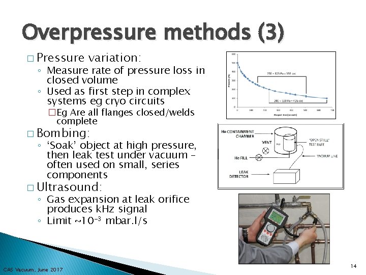
Overpressure methods (3) � Pressure variation: ◦ Measure rate of pressure loss in closed volume ◦ Used as first step in complex systems eg cryo circuits �Eg Are all flanges closed/welds complete � Bombing: ◦ ‘Soak’ object at high pressure, then leak test under vacuum – often used on small, series components � Ultrasound: ◦ Gas expansion at leak orifice produces k. Hz signal ◦ Limit ~10 -3 mbar. l/s CAS Vacuum, June 2017 14
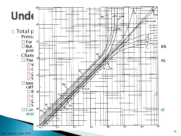
Under vacuum methods � Total pressure gauge ◦ Pressure rise � For large leaks only � But, must know outgassing load from measurement or comparison with previous tests ◦ Change of gauge reading – gauges are gas dependent � Thermal conductivity effect for Pirani gauge (when in measuring range), � With N 2 as reference � Gauge reading when spraying Ar ↘, He ↗, Alcohol ↗ � Qualitative method to determine the presence of a leak � Sensitivity will depend on leak, pump and gauge position � Ionisation probabilities for ion gauge - hot (SVT) or cold (Penning) cathode types � Relative ionization probability for N 2 = 1, Ar = 1. 2, He = 0. 15 � Gauge reading when spraying Ar↗, He↘ � Qualitative method to determine the presence of a leak � Sensitivity will depend on leak, pump and gauge position � Can be useful techniques to keep in mind if helium leak detector is not available or can’t be connected to system. CAS Vacuum, June 2017 15
Under vacuum methods(2) � Total pressure gauge ◦ Change of gauge reading due to (temporary) plugging of the leak �Alcohol �Vacuum grease (not recommended) �Mastic (not recommended) �Varnish (temporary repairs) � Helium leak detector – see next � Partial pressure gauge - Residual gas analyser ◦ ◦ Fixed or added in vacuum system, sensitivity 10 -12 mbarl/s Mass 4 as helium leak detector Signature for air leaks Ar, O 2, etc. Leak testing with neon �LHC cryomodules already contaminated with helium �If NEG present – use gauge sensitivity and conductance effects for leak localisation CAS Vacuum, June 2017 16

The mass spectrometer leak detector (MSLD)… An expensive, mobile, ‘black box’ that evacuates the chamber to be tested and reads helium signals! CAS Vacuum, June 2017 17
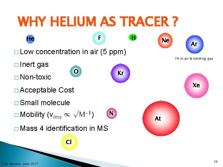
WHY HELIUM AS TRACER ? F He � Low � Inert H Ne concentration in air (5 ppm) 1% in air & welding gas O � Non-toxic � Acceptable � Small Kr Xe Cost molecule � Mobility � Mass Ar (vrms ∝ √M-1) N At 4 identification in MS Cl CAS Vacuum, June 2017 18
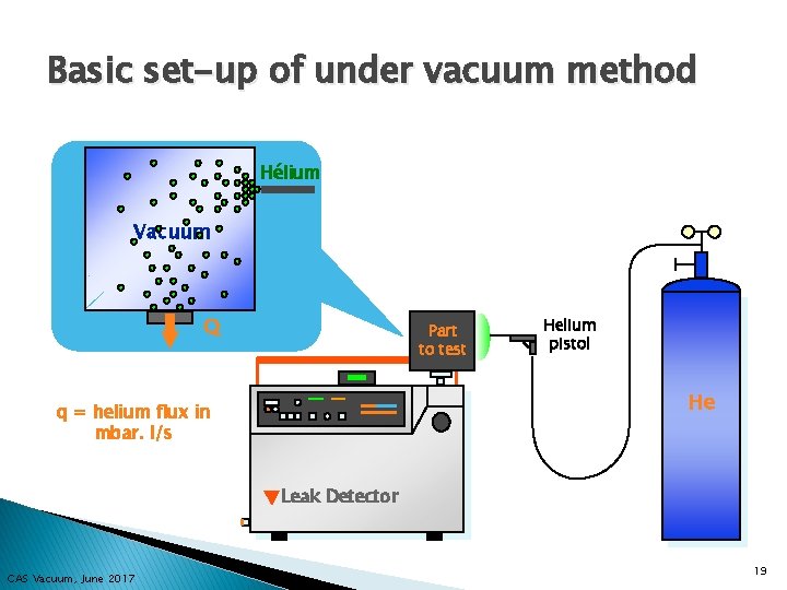
Basic set-up of under vacuum method Hélium Vacuum Q Part to test Helium pistol He q = helium flux in mbar. l/s Leak Detector CAS Vacuum, June 2017 19
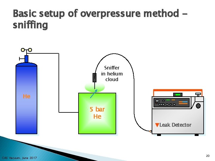
Basic setup of overpressure method sniffing Sniffer in helium cloud He 5 bar He Leak Detector CAS Vacuum, June 2017 20
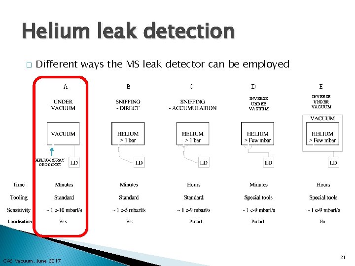
Helium leak detection � Different ways the MS leak detector can be employed A B C D INVERSE UNDER VACUUM E INVERSE UNDER VACUUM HELIUM SPRAY OR POCKET Localisation Yes CAS Vacuum, June 2017 Yes Partial No 21
Leak detection -Common methods TEST METHOD Flux in atm. cm 3/s or mbar. l/s Bubble test Over pressure Pressure variation Over pressure Sniffing halogens or H 2 N 2 Helium mass spectrometer Residual gas analyser Under vacuum Over pressure (sniffing) Under vacuum 102 101 100 10 -1 10 -2 10 -3 10 -4 10 -5 10 -6 10 -8 10 -10 10 -12 CAS Vacuum, June 2017 22
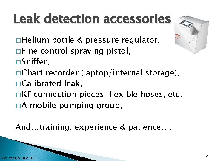
Leak detection accessories � Helium bottle & pressure regulator, � Fine control spraying pistol, � Sniffer, � Chart recorder (laptop/internal storage), � Calibrated leak, � KF connection pieces, flexible hoses, etc. � A mobile pumping group, And…training, experience & patience…. CAS Vacuum, June 2017 23
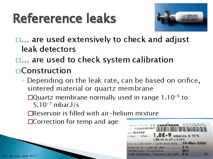
Refererence leaks �… are used extensively to check and adjust leak detectors � … are used to check system calibration � Construction ◦ Depending on the leak rate, can be based on orifice, sintered material or quartz membrane �Quartz membrane normally used in range 1. 10 -9 to 5. 10 -7 mbar. l/s �Reservoir is filled with air-helium mixture �Correction for temp and age CAS Vacuum, June 2017 24

The leak signal…determining the size � Need to apply corrections to the observed leak signal to determine the leak size ◦ Subtract the residual signal ◦ Apply coefficient for helium concentration ◦ Apply correction for detector response to an external calibrated leak � Leak CAS Vacuum, June 2017 size 25
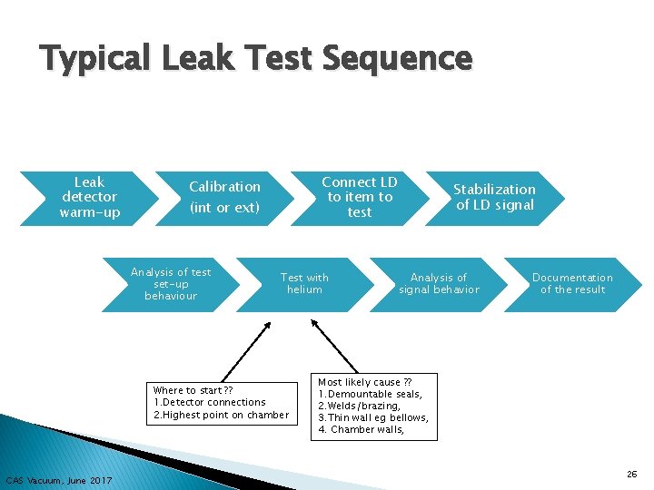
Typical Leak Test Sequence Leak detector warm-up Connect LD to item to test Calibration (int or ext) Analysis of test set-up behaviour Test with helium Where to start ? ? 1. Detector connections 2. Highest point on chamber CAS Vacuum, June 2017 Stabilization of LD signal Analysis of signal behavior Documentation of the result Most likely cause ? ? 1. Demountable seals, 2. Welds/brazing, 3. Thin wall eg bellows, 4. Chamber walls, 26
PRACTICAL 1 ◦ 2 Groups of 8 students ◦ 4 x ~10 minutes ◦ Test stand 1 – Get acquainted with LD & He bottle ◦ Test stand 2 – Get acquainted with LD & calibration/acquisition ◦ Test stand 3 – Leak detection on bellows ◦ Test stand 4 – Leak detection on serpentine tube ◦ Discussion CAS Vacuum, June 2017 27
Leak Detection – Part 2 ◦ Inside the leak detector…. ◦ The leak signal…. . ◦ (Further details and reading) ◦ Practical 2 CAS Vacuum, June 2017 28
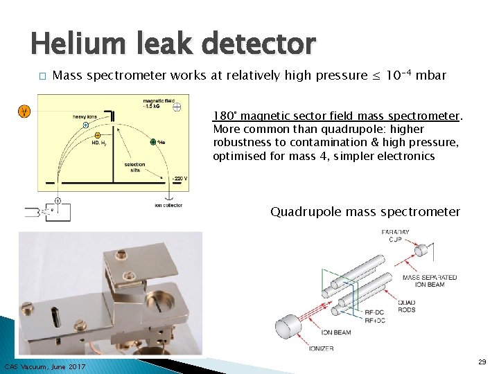
Helium leak detector � Mass spectrometer works at relatively high pressure ≤ 10 -4 mbar 180° magnetic sector field mass spectrometer. More common than quadrupole: higher robustness to contamination & high pressure, optimised for mass 4, simpler electronics Quadrupole mass spectrometer CAS Vacuum, June 2017 29
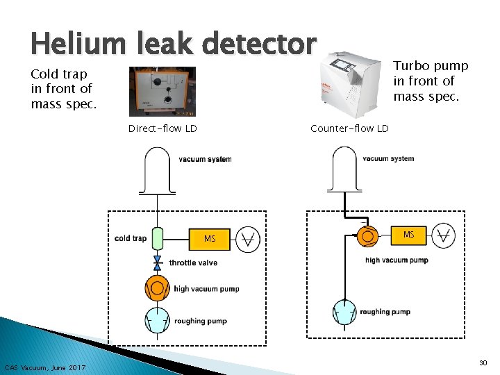
Helium leak detector Cold trap in front of mass spec. Direct-flow LD Counter-flow LD MS CAS Vacuum, June 2017 Turbo pump in front of mass spec. MS 30
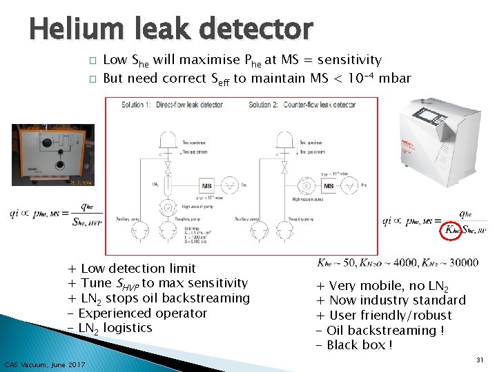
Helium leak detector � � Low She will maximise Phe at MS = sensitivity But need correct Seff to maintain MS < 10 -4 mbar + Low detection limit + Tune SHVP to max sensitivity + LN 2 stops oil backstreaming - Experienced operator - LN 2 logistics CAS Vacuum, June 2017 + Very mobile, no LN 2 + Now industry standard + User friendly/robust - Oil backstreaming ! - Black box ! 31
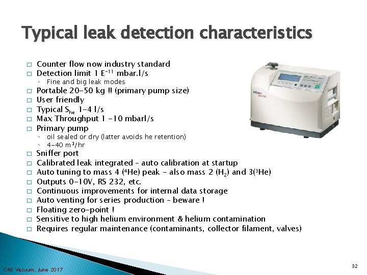
Typical leak detection characteristics � � Counter flow now industry standard Detection limit 1 E-11 mbar. l/s ◦ Fine and big leak modes � � � Portable 20 -50 kg !! (primary pump size) User friendly Typical She 1 -4 l/s Max Throughput 1 -10 mbarl/s Primary pump ◦ oil sealed or dry (latter avoids he retention) ◦ 4 -40 m 3/hr � � � � � Sniffer port Calibrated leak integrated – auto calibration at startup Auto tuning to mass 4 (4 He) peak - also mass 2 (H 2) and 3(3 He) Outputs 0 -10 V, RS 232, etc. Continuous improvements for internal data storage Auto venting for series production – beware ! Floating zero-point ! Sensitive to high helium environment & helium contamination Requires regular maintenance (contaminants, collector filament, valves) CAS Vacuum, June 2017 32
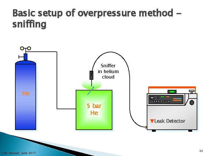
Basic setup of overpressure method sniffing Sniffer in helium cloud He 5 bar He Leak Detector CAS Vacuum, June 2017 33
Overpressure methods � Helium Sniffing: ◦ Principle to detect an increased helium concentration at the leak with respect to a background signal ◦ The background is due to the natural 5 ppm helium in air (in cryo environments this can be higher). ◦ The sniffer is directly sampling the gas mixture in the ambient air via a sintered plug, and an increase in helium concentration is seen in the leak detector cell. ◦ Typically 2 to 5 m tube length ◦ Sniffing is a localisation method, often employed once a leak is known to exist. ◦ System must be able to support overpressure � Above 1. 5 bar (absolute) safety rules apply ◦ Can be employed on complex geometries ◦ The detection limit depends of the sniffer pumping speed and the sensitivity of the detector cell � Detection limit for direct sniffing ~ 10 -5/10 -6 mbar. l/s ◦ The detection limit can be greatly improved by accumulation of the leaking helium in a pocket � Detection limit for sniffing with accumulation ~ 10 -9 mbar. l/s CAS Vacuum, June 2017 34
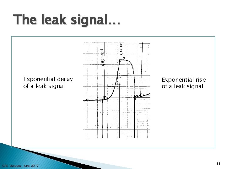
The leak signal… Exponential decay of a leak signal CAS Vacuum, June 2017 Exponential rise of a leak signal 35
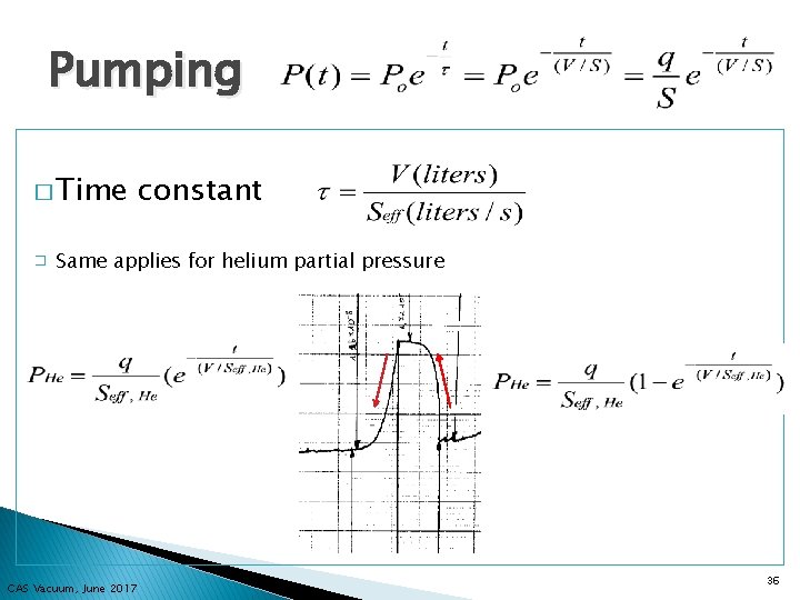
Pumping � Time � constant Same applies for helium partial pressure CAS Vacuum, June 2017 36
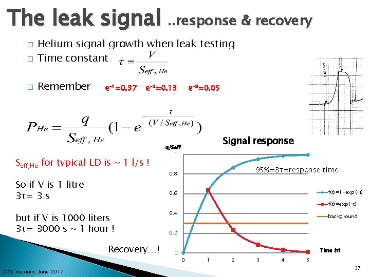
The leak signal. . response & recovery � Helium signal growth when leak testing Time constant � Remember � e-1=0. 37 e-2=0. 13 Seff, He for typical LD is ~ 1 l/s ! So if V is 1 litre 3τ= 3 s Signal response q/Seff 1 95%=3τ=response time 0. 8 f(t)=1 -exp(-t) 0. 6 f(t)=exp(-t) but if V is 1000 liters 3τ= 3000 s ~ 1 hour ! Recovery…! CAS Vacuum, June 2017 e-3=0. 05 0. 4 background 0. 2 0 Time (τ) 0 1 2 3 4 5 37
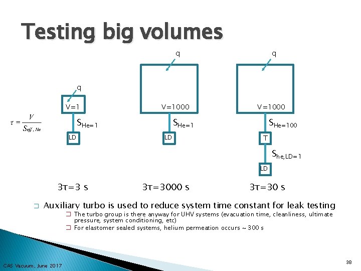
Testing big volumes q q q V=1000 SHe=1 LD SHe=100 T She, LD=1 LD 3τ=3 s � 3τ=3000 s 3τ=30 s Auxiliary turbo is used to reduce system time constant for leak testing � The turbo group is there anyway for UHV systems (evacuation time, cleanliness, ultimate pressure, system conditioning, etc) � For elastomer sealed systems, helium permeation occurs ~ 300 s CAS Vacuum, June 2017 38
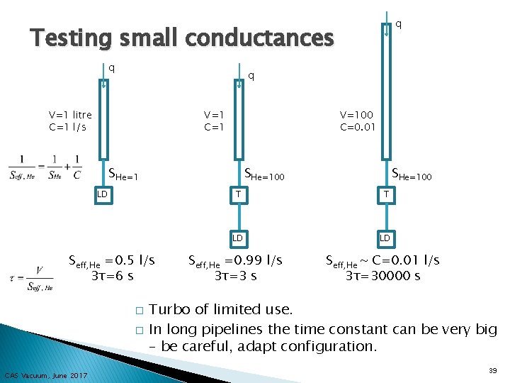
q Testing small conductances q q V=1 litre C=1 l/s V=1 C=1 V=100 C=0. 01 SHe=100 LD Seff, He =0. 5 l/s 3τ=6 s � � CAS Vacuum, June 2017 SHe=100 T T LD LD Seff, He =0. 99 l/s 3τ=3 s Seff, He ~ C=0. 01 l/s 3τ=30000 s Turbo of limited use. In long pipelines the time constant can be very big – be careful, adapt configuration. 39
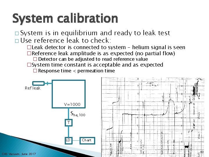
System calibration � System is in equilibrium and ready to leak test � Use reference leak to check: �Leak detector is connected to system - helium signal is seen �Reference leak amplitude is as expected (no partial flow) � Detector can be adjusted to read reference value �System time constant is acceptable and as expected � Response time < permeation time Ref leak V=1000 She, 100 T LD CAS Vacuum, June 2017 Chart 40
High background signal � Due to leak detector: � Due to system under test ◦ ◦ ◦ ◦ ◦ Polluted detector (He contaminated oil, seals, collector, etc) Calibration of detector Malfunctioning of detector Leaks in internal connections Leaks (5 ppm helium in air) Virtual leaks Permeation through elastomer seals High helium environment (> 5 ppm) Materials in system retaining helium (oil, grease, etc) CAS Vacuum, June 2017 41
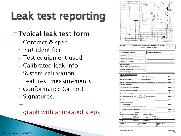
Leak test reporting � Typical leak test form ◦ Contract & spec ◦ Part identifier ◦ Test equipment used ◦ Calibrated leak info ◦ System calibration ◦ Leak test measurements ◦ Conformance (or not) ◦ Signatures. + ◦ graph with annotated steps CAS Vacuum, June 2017 42
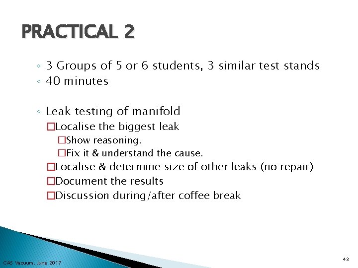
PRACTICAL 2 ◦ 3 Groups of 5 or 6 students, 3 similar test stands ◦ 40 minutes ◦ Leak testing of manifold �Localise the biggest leak �Show reasoning. �Fix it & understand the cause. �Localise & determine size of other leaks (no repair) �Document the results �Discussion during/after coffee break CAS Vacuum, June 2017 43
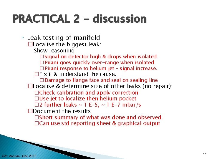
PRACTICAL 2 - discussion ◦ Leak testing of manifold �Localise the biggest leak: Show reasoning �Signal on detector high & drops when isolated �Pirani goes quickly over-range when isolated �Pirani response to helium jet – signal increase. �Fix it & understand the cause. �Damage to flange face and seal on sealing line �Localise & determine size of other leaks (no repair): �Check calibration and apply correction �Use jet to localize then helium pocket � 2 further leaks ~ 1 E-5, ~ 1 E-7 mbar/s �Document the results �Short summary of what was done and observed. �Can use std reporting sheet & graphical output CAS Vacuum, June 2017 44
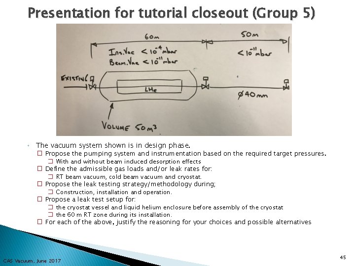
Presentation for tutorial closeout (Group 5) ◦ The vacuum system shown is in design phase. � Propose the pumping system and instrumentation based on the required target pressures. � � � With and without beam induced desorption effects Define the admissible gas loads and/or leak rates for: � RT beam vacuum, cold beam vacuum and cryostat. Propose the leak testing strategy/methodology during; � Construction, installation and operation. Propose a leak test setup for: � the cryostat vessel and liquid helium enclosure before assembly of the cryostat � the 60 m RT zone during its installation. For each of the above, justify the reasoning for your choices and possible alternatives CAS Vacuum, June 2017 45

Further slides……. CAS Vacuum, June 2017 46
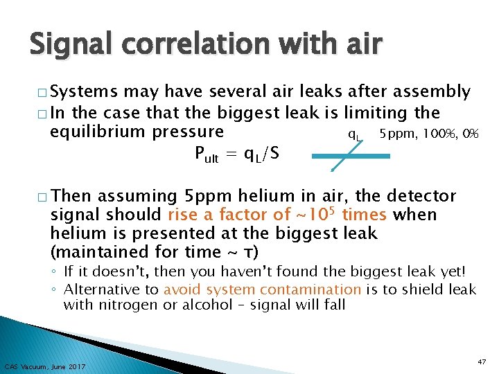
Signal correlation with air � Systems may have several air leaks after assembly � In the case that the biggest leak is limiting the equilibrium pressure q. L 5 ppm, 100%, 0% Pult = q. L/S � Then assuming 5 ppm helium in air, the detector signal should rise a factor of ~105 times when helium is presented at the biggest leak (maintained for time ~ τ) ◦ If it doesn’t, then you haven’t found the biggest leak yet! ◦ Alternative to avoid system contamination is to shield leak with nitrogen or alcohol – signal will fall CAS Vacuum, June 2017 47
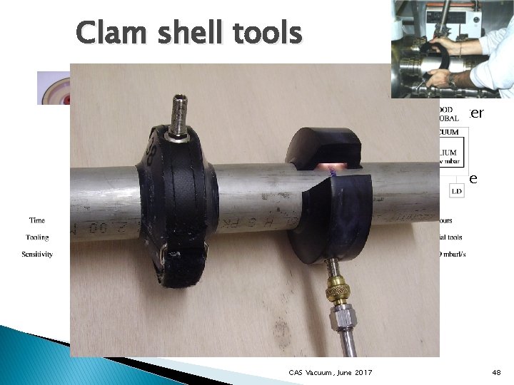
Clam shell tools � � ~20 diameters and diameter combinations for LSS standalones NBR, polyurethane, silicone rubber, metal+mastic CAS Vacuum, June 2017 48
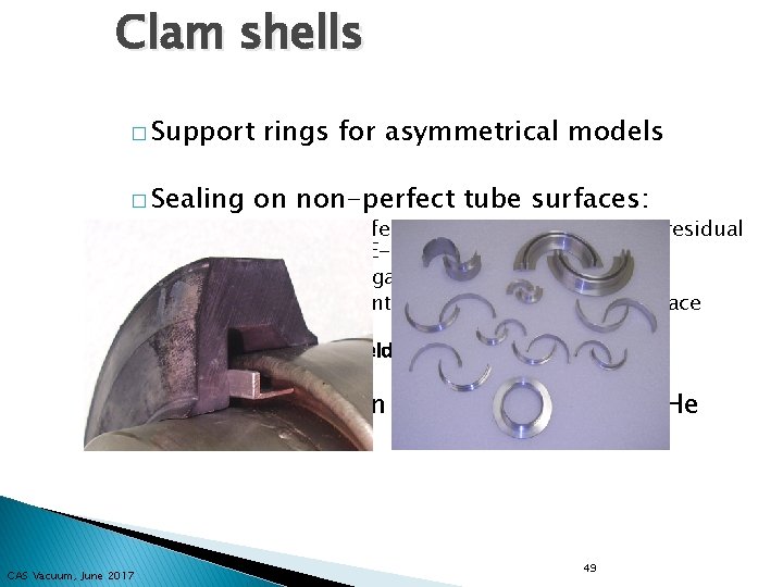
Clam shells � Support � Sealing rings for asymmetrical models on non-perfect tube surfaces: ◦ alcohol for small defects to allow a E-8 mbar. l/s residual signal to reduce to E-10 range ◦ mastic for bridging gaps ◦ vacuum grease for intermediate defects (e. g. surface scratches) � Same space as orbital welding machine � Clam shells retain He – do not store in He atmosphere CAS Vacuum, June 2017 49
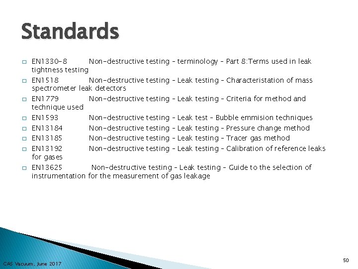
Standards � � � � EN 1330 -8 Non-destructive testing – terminology – Part 8: Terms used in leak tightness testing EN 1518 Non-destructive testing – Leak testing – Characteristation of mass spectrometer leak detectors EN 1779 Non-destructive testing – Leak testing – Criteria for method and technique used EN 1593 Non-destructive testing – Leak test – Bubble emmision techniques EN 13184 Non-destructive testing – Leak testing – Pressure change method EN 13185 Non-destructive testing – Leak testing – Tracer gas method EN 13192 Non-destructive testing – Leak testing – Calibration of reference leaks for gases EN 13625 Non-destructive testing – Leak testing – Guide to the selection of instrumentation for the measurement of gas leakage CAS Vacuum, June 2017 50
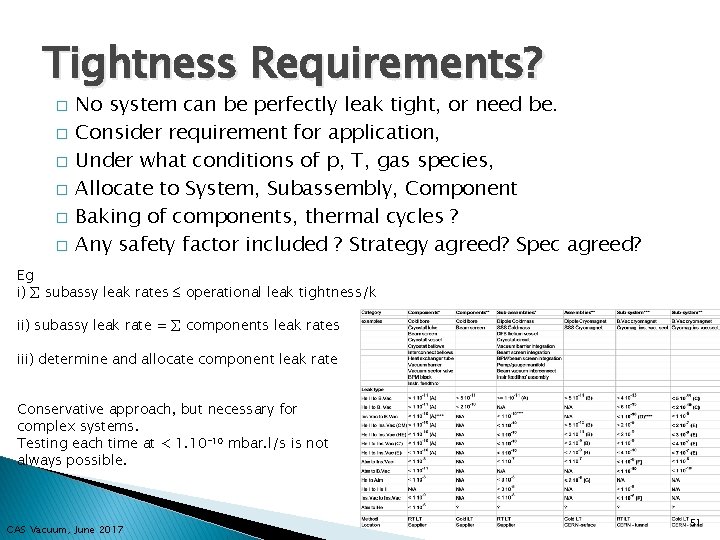
Tightness Requirements? � � � No system can be perfectly leak tight, or need be. Consider requirement for application, Under what conditions of p, T, gas species, Allocate to System, Subassembly, Component Baking of components, thermal cycles ? Any safety factor included ? Strategy agreed? Spec agreed? Eg i) subassy leak rates operational leak tightness/k ii) subassy leak rate = components leak rates iii) determine and allocate component leak rate Conservative approach, but necessary for complex systems. Testing each time at < 1. 10 -10 mbar. l/s is not always possible. CAS Vacuum, June 2017 51
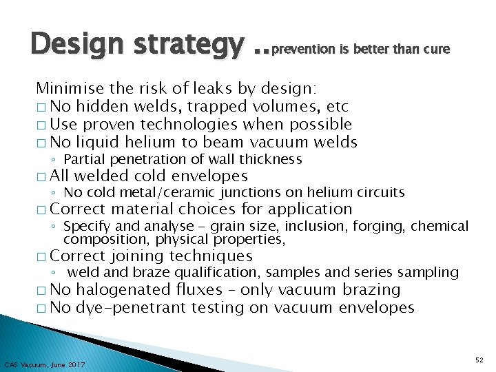
Design strategy. . prevention is better than cure Minimise the risk of leaks by design: � No hidden welds, trapped volumes, etc � Use proven technologies when possible � No liquid helium to beam vacuum welds ◦ Partial penetration of wall thickness � All welded cold envelopes ◦ No cold metal/ceramic junctions on helium circuits � Correct material choices for application � Correct joining techniques ◦ Specify and analyse - grain size, inclusion, forging, chemical composition, physical properties, ◦ weld and braze qualification, samples and series sampling � No halogenated fluxes – only vacuum brazing � No dye-penetrant testing on vacuum envelopes CAS Vacuum, June 2017 52
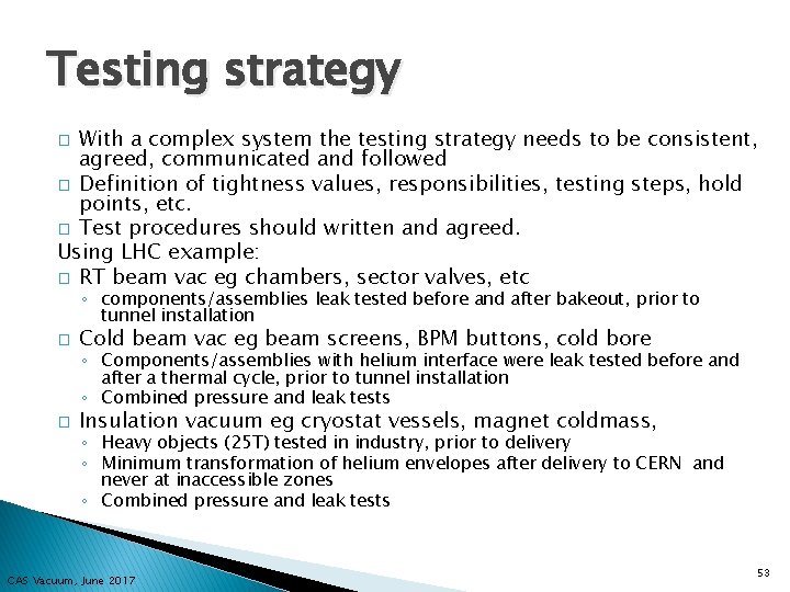
Testing strategy With a complex system the testing strategy needs to be consistent, agreed, communicated and followed � Definition of tightness values, responsibilities, testing steps, hold points, etc. � Test procedures should written and agreed. Using LHC example: � RT beam vac eg chambers, sector valves, etc � ◦ components/assemblies leak tested before and after bakeout, prior to tunnel installation � Cold beam vac eg beam screens, BPM buttons, cold bore ◦ Components/assemblies with helium interface were leak tested before and after a thermal cycle, prior to tunnel installation ◦ Combined pressure and leak tests � Insulation vacuum eg cryostat vessels, magnet coldmass, ◦ Heavy objects (25 T) tested in industry, prior to delivery ◦ Minimum transformation of helium envelopes after delivery to CERN and never at inaccessible zones ◦ Combined pressure and leak tests CAS Vacuum, June 2017 53
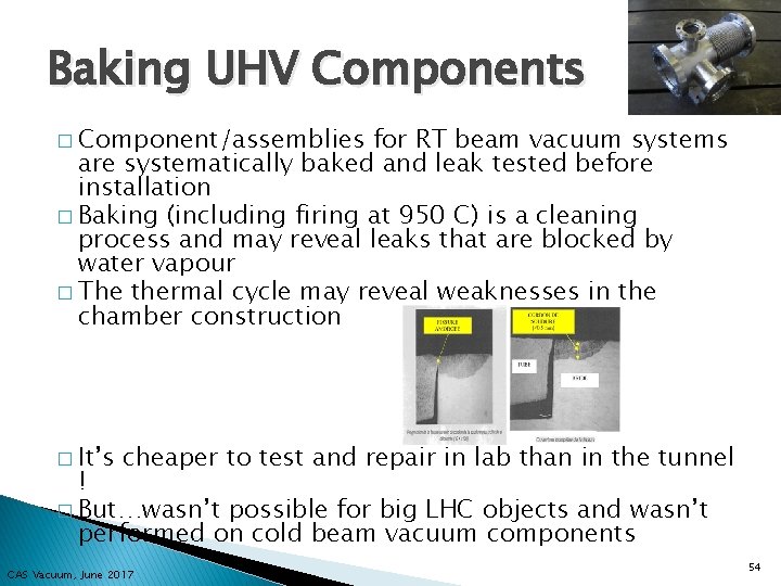
Baking UHV Components � Component/assemblies for RT beam vacuum systems are systematically baked and leak tested before installation � Baking (including firing at 950 C) is a cleaning process and may reveal leaks that are blocked by water vapour � The thermal cycle may reveal weaknesses in the chamber construction � It’s cheaper to test and repair in lab than in the tunnel ! � But…wasn’t possible for big LHC objects and wasn’t performed on cold beam vacuum components CAS Vacuum, June 2017 54
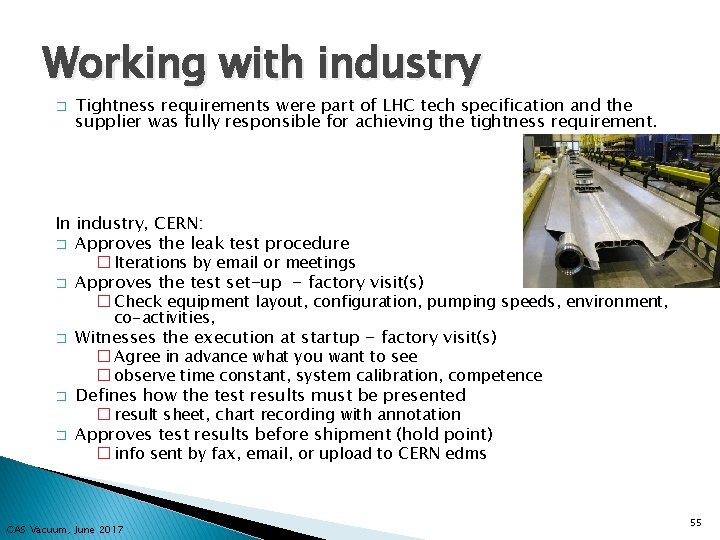
Working with industry � Tightness requirements were part of LHC tech specification and the supplier was fully responsible for achieving the tightness requirement. In industry, CERN: � Approves the leak test procedure � Iterations by email or meetings � Approves the test set-up - factory visit(s) � Check equipment layout, configuration, pumping speeds, environment, co-activities, � � � Witnesses the execution at startup - factory visit(s) � Agree in advance what you want to see � observe time constant, system calibration, competence Defines how the test results must be presented � result sheet, chart recording with annotation Approves test results before shipment (hold point) � info sent by fax, email, or upload to CERN edms CAS Vacuum, June 2017 55

Types of leaks � Demountable connections � Permanent connections � Flaws in wall material ◦ metal seals, elastomer seals ◦ Welded, brazed, glass/metal, ceramic/metal, bonded ◦ ◦ � � Thin walls – bellows, flexible hoses Changes of x-section Cracks, inclusions, porosity, corrosion, fatigue… Damage – shocks, TIG arc, Many more…. Priorities in leak search could follow order above but get info on history – previous test (who, when, how), recent modifications, transport, thermal cycles, pressure cycles, flux, storage, etc. CAS Vacuum, June 2017 56
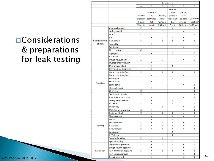
� Considerations & preparations for leak testing CAS Vacuum, June 2017 57
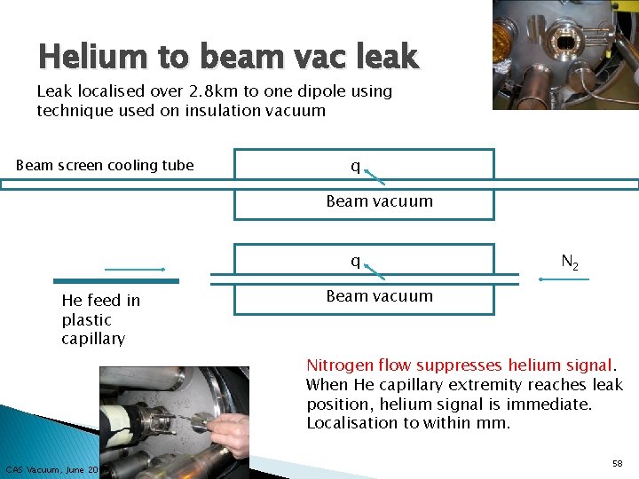
Helium to beam vac leak Leak localised over 2. 8 km to one dipole using technique used on insulation vacuum Beam screen cooling tube q Beam vacuum q He feed in plastic capillary N 2 Beam vacuum Nitrogen flow suppresses helium signal. When He capillary extremity reaches leak position, helium signal is immediate. Localisation to within mm. CAS Vacuum, June 2017 58
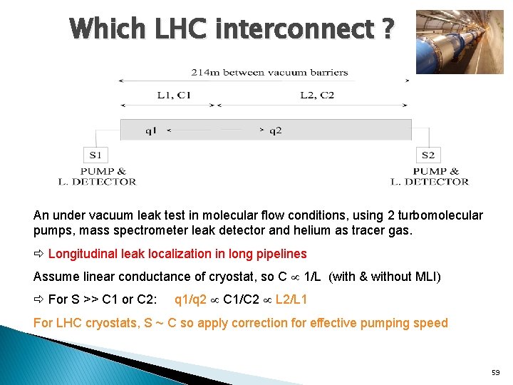
Which LHC interconnect ? An under vacuum leak test in molecular flow conditions, using 2 turbomolecular pumps, mass spectrometer leak detector and helium as tracer gas. Longitudinal leak localization in long pipelines Assume linear conductance of cryostat, so C 1/L (with & without MLI) For S >> C 1 or C 2: q 1/q 2 C 1/C 2 L 2/L 1 For LHC cryostats, S ~ C so apply correction for effective pumping speed 59
- Slides: 59