Leachate Collection Systems Class Objectives To discuss landfill

Leachate Collection Systems

Class Objectives Ø To discuss landfill water balance Ø To present liner and leachate collection system (LCS) design information Ø To discuss clogging problems


Liner and LCS Design Ø Select liner type Ø Leachate flow rates (25 -yr storm - 0. 36 in/hr) Ø Pipe spacing Ø Pipe flow Ø Pipe diameter Ø Design filter


Waste Containment Liners Waste Leachate collection Protection geotextile Geomembrane Geosynthetic Clay Liner Subsoil Common containment regulations require different sealing systems for nonhazardous and hazardous containments. In general the lining system is a composite lining system.
 –")
Liner Types Ø Composite – Soil (clay – 60 cm, 10 -7 cm/sec) – Geosynthetic (1. 5 mm) – Geocomposite Ø Double

Single Composite Liner

Double Geomembrane Liner Geomembrane or GCL

Double Liner with Bottom Geocomposite Composite

Double Composite Liner

Materials in Liner system ~ Clay Liner Low permeability soil kd = 1 x 10 -7 cm/sec t Subgrade
 sheet with a minimum thickness of 1.")
Geomembrane A planar, relatively impermeable, polymeric (synthetic) sheet with a minimum thickness of 1. 0 mm. In landfill applications they are most commonly of HDPE with a thickness of > 1. 0 mm. The surface can be smooth , profiled or textured and can be of importance for the shear behaviour.
 An assembled structure of geosynthetic materials and low hydraulic conductivity")
Geosynthetic Clay Liner (GCL) An assembled structure of geosynthetic materials and low hydraulic conductivity earth materials (usually bentonite). The clay layer is encapsulated between geosynthetics (cover and carrier geotextile) or bonded to a geosynthetic. Shear force transferring GCLs are needle-punched or stitchbonded.

Leachate Collection System
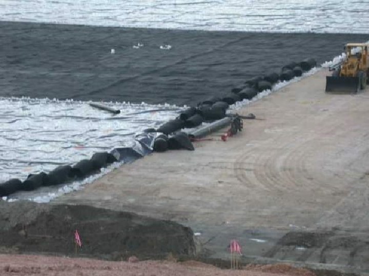


Installation of a GCL barrier in the base of a MSW landfill


Drain design configurations

Leachate Collection System with Sloped Subgrade
")
Head on Liner – Florida Regulations (Composite Liner)

Leachate Collection System

Pipe Spacing q k Slope Hmax L/2 Collection pipe
")
Spatial Distribution of Head (Mc. Enroe’s Equation)

Slotted Collection Pipes

Spacing Between Pipes Using a Geonet

Leachate Removal System

Pipe flow Qin pipe = q Lb Where: q = Infiltration rate, L/T L = pipe spacing, L b = length of pipe, L

Pipe Diameter Ø Assume pipe is flowing full Ø Use Manning Equation Ø check velocity is sufficient (>2 fps) Ø Diameter is commercially available (not 3. 2 in!)

Leachate Collection – Double Liner

Leachate Collection Pump

Causes of Leachate Collection System Failure Ø Clogging due to particulate transport/chemical precipitation Ø Clogging due to biological material buildup Ø Pipe breakage/slope change

Biological Clogging Ø Bacteria secret extra cellular polysaccharides to form gelatinous matrix or biofilm Ø Biofilm acts as a filter within filter, trapping particles

Chemical Precipitation Ø Metals are mobilized in leachate Ø Carbonates and sulfides present in anaerobic environment lead to metal precipitation Ø Little silts or other fines Ø Primary threat during acidic phases Ø Opening size critical factor

Implications of LCS Failure Ø Excess head on liner Ø Increased risk associated with potential liner failure Ø Side seeps Ø Reduced leachate output Ø Landfill instability

LCS Failure Contributors Ø Carbonate in drainage rock/leachate interaction Ø Geotextile-wrapped collection pipes Ø Slope change due to settling and compression of subgrade Ø Crushed pipe

LCS Failure Contributors Cont’d Ø Overhandling of drainage material production of fines Ø Creep/clogging of geonets Ø Adverse leachate p. H Ø Change in partial pressure of CO 2

Clogging Prevention Ø Proper filter design – Use of safety factors – Proper placement Ø Proper selection of materials

Backflushing has Transitory Impact on Filter Clogging

Return to Home Page Last updated 25 November 2020 by Dr. Reinhart
- Slides: 44