
LCLSIISC Parameters Tor Raubenheimer 1012013 LCLSII Linac and
LCLS-IISC Parameters Tor Raubenheimer 10/1/2013
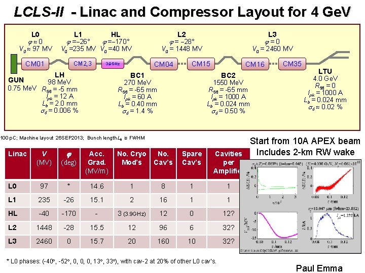
LCLS-II - Linac and Compressor Layout for 4 Ge. V L 0 j 0 V 0 97 MV L 1 j =-26° HL j =-170° V 0 =235 MV V 0 =40 MV CM 01 CM 2, 3 V 0 = 2460 MV CM 15 BC 1 98 Me. V 0. 75 Me. V R 56 = -5 mm Ipk = 12 A Lb = 2. 0 mm sd = 0. 006 % L 3 j = 0 V 0 = 1448 MV CM 04 3. 9 GHz LH GUN L 2 j = -28° CM 16 BC 2 270 Me. V R 56 = -65 mm Ipk = 60 A Lb = 0. 40 mm sd = 1. 4 % 1550 Me. V R 56 = -65 mm Ipk = 1000 A Lb = 0. 024 mm sd = 0. 50 % 100 p. C; Machine layout 26 SEP 2013; Bunch length Lb is FWHM Linac V (MV) L 0 j (deg) Acc. Grad. (MV/m) No. Cryo Mod’s No. Cav’s Spare Cav’s Cavities per Amplifier 97 * 14. 6 1 8 1 1 L 1 235 -26 15. 1 2 16 1 1 HL -40 -170 - 3 (3. 9 GHz) 12 0 12? L 2 1448 -28 15. 5 12 96 6 32? L 3 2460 0 15. 7 20 160 10 32? * L 0 phases: (-40 , -52 , 0, 0, 0, 13 , 33 ), with cav-2 at 20% of other L 0 cav’s. CM 35 LTU 4. 0 Ge. V R 56 = 0 Ipk = 1000 A Lb = 0. 024 mm sd 0. 02 % Start from 10 A APEX beam Includes 2 -km RW wake Paul Emma
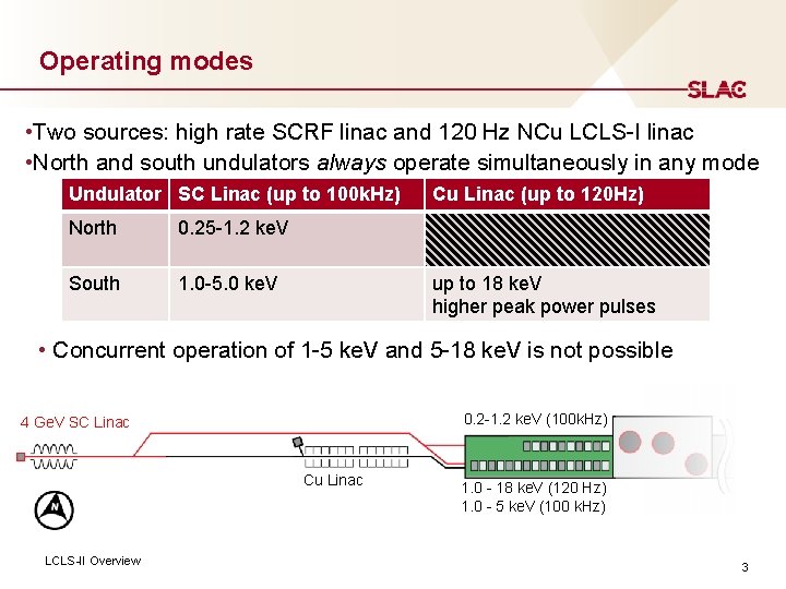
Operating modes • Two sources: high rate SCRF linac and 120 Hz NCu LCLS-I linac • North and south undulators always operate simultaneously in any mode Undulator SC Linac (up to 100 k. Hz) North 0. 25 -1. 2 ke. V South 1. 0 -5. 0 ke. V Cu Linac (up to 120 Hz) up to 18 ke. V higher peak power pulses • Concurrent operation of 1 -5 ke. V and 5 -18 ke. V is not possible 0. 2 -1. 2 ke. V (100 k. Hz) 4 Ge. V SC Linac Cu Linac LCLS-II Overview 1. 0 - 18 ke. V (120 Hz) 1. 0 - 5 ke. V (100 k. Hz) 3
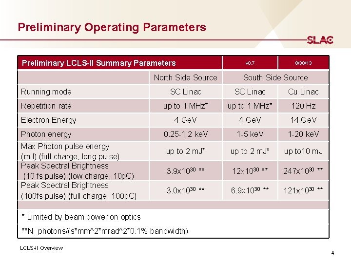
Preliminary Operating Parameters Preliminary LCLS-II Summary Parameters North Side Source v 0. 7 8/30/13 South Side Source Running mode SC Linac Cu Linac Repetition rate up to 1 MHz* 120 Hz 4 Ge. V 14 Ge. V 0. 25 -1. 2 ke. V 1 -5 ke. V 1 -20 ke. V up to 2 m. J* up to 10 m. J 3. 9 x 1030 ** 12 x 1030 ** 247 x 1030 ** 3. 0 x 1030 ** 6. 9 x 1030 ** 121 x 1030 ** Electron Energy Photon energy Max Photon pulse energy (m. J) (full charge, long pulse) Peak Spectral Brightness (10 fs pulse) (low charge, 10 p. C) Peak Spectral Brightness (100 fs pulse) (full charge, 100 p. C) * Limited by beam power on optics **N_photons/(s*mm^2*mrad^2*0. 1% bandwidth) LCLS-II Overview 4
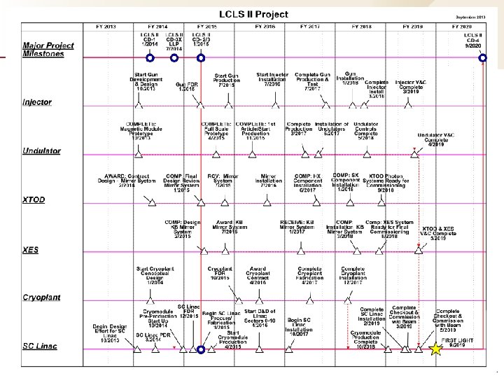
High Level Schedule Insert Presentation Title in Slide Master 5
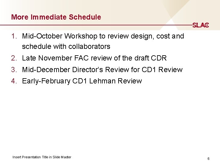
More Immediate Schedule 1. Mid-October Workshop to review design, cost and schedule with collaborators 2. Late November FAC review of the draft CDR 3. Mid-December Director’s Review for CD 1 Review 4. Early-February CD 1 Lehman Review Insert Presentation Title in Slide Master 6
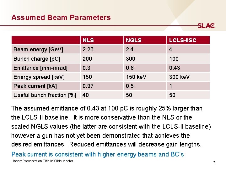
Assumed Beam Parameters NLS NGLS LCLS-IISC Beam energy [Ge. V] 2. 25 2. 4 4 Bunch charge [p. C] 200 300 100 Emittance [mm-mrad] 0. 3 0. 6 0. 43 Energy spread [ke. V] 150 ke. V 300 ke. V Peak current [k. A] 0. 97 0. 5 1 Useful bunch fraction [%] 40 50 50 The assumed emittance of 0. 43 at 100 p. C is roughly 25% larger than the LCLS-II baseline. It is more conservative than the NLS or the scaled NGLS values (the latter are consistent with the LCLS-II baseline) however a gun has not yet been demonstrated that achieves the desired emittances. Reduced emittances will decrease gain lengths. Peak current is consistent with higher energy beams and BC’s Insert Presentation Title in Slide Master 7
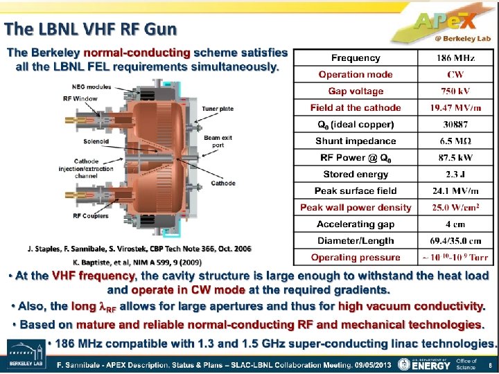
Example of Injector: APEX Insert Presentation Title in Slide Master 8
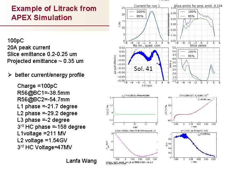
Example of Litrack from APEX Simulation 100 p. C 20 A peak current Slice emittance 0. 2 -0. 25 um Projected emittance ~ 0. 35 um Ø better current/energy profile Charge =100 p. C R 56@BC 1=-38. 5 mm R 56@BC 2=-54. 7 mm L 1 phase =-21. 7 degree L 2 phase =-29. 2 degree L 3 phase =-2 degree 3 rd HC phase =-158 degree L 1 voltage =211 MV L 2 voltage =1. 54 GV 3 rd HC Voltage=47 MV Lanfa Wang 9
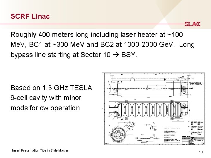
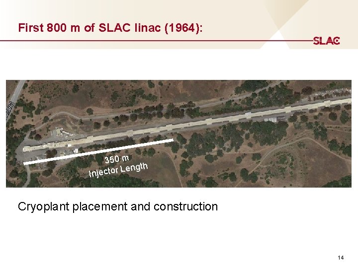
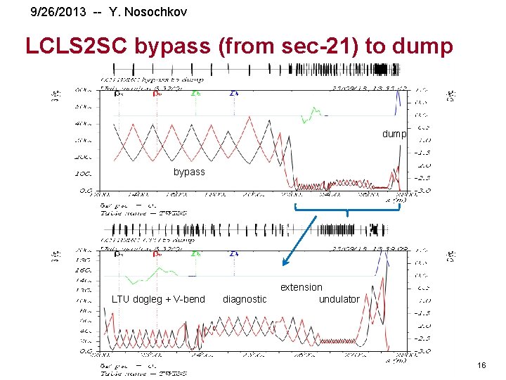
SCRF Linac Roughly 400 meters long including laser heater at ~100 Me. V, BC 1 at ~300 Me. V and BC 2 at 1000 -2000 Ge. V. Long bypass line starting at Sector 10 BSY. Based on 1. 3 GHz TESLA 9 -cell cavity with minor mods for cw operation Insert Presentation Title in Slide Master 10
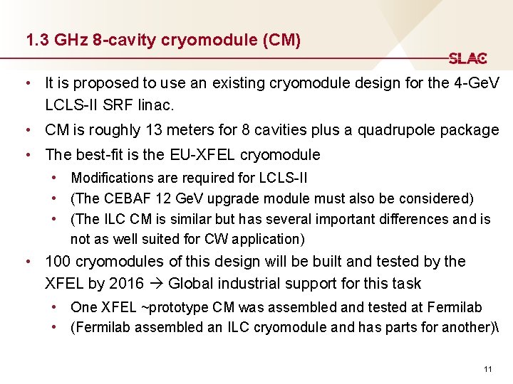
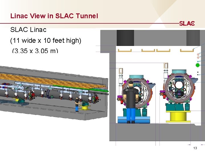
1. 3 GHz 8 -cavity cryomodule (CM) • It is proposed to use an existing cryomodule design for the 4 -Ge. V LCLS-II SRF linac. • CM is roughly 13 meters for 8 cavities plus a quadrupole package • The best-fit is the EU-XFEL cryomodule • Modifications are required for LCLS-II • (The CEBAF 12 Ge. V upgrade module must also be considered) • (The ILC CM is similar but has several important differences and is not as well suited for CW application) • 100 cryomodules of this design will be built and tested by the XFEL by 2016 Global industrial support for this task • One XFEL ~prototype CM was assembled and tested at Fermilab • (Fermilab assembled an ILC cryomodule and has parts for another) 11
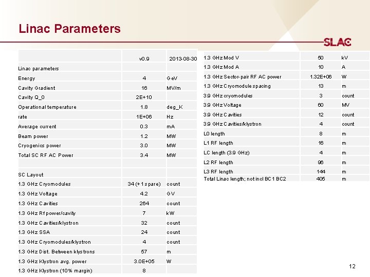
Linac Parameters v 0. 9 2013 -08 -30 Linac parameters 1. 3 GHz Mod V 50 k. V 1. 3 GHz Mod A 10 A 1. 32 E+06 W Energy 4 Ge. V 1. 3 GHz Sector-pair RF AC power Cavity Gradient 16 MV/m 1. 3 GHz Cryomodule spacing 13 m 3. 9 GHz cryomodules 3 count deg_K 3. 9 GHz Voltage 60 MV 1 E+06 Hz 3. 9 GHz Cavities 12 count Average current 0. 3 m. A 3. 9 GHz Cavities/klystron 4 count Beam power 1. 2 MW L 0 length 8 m Cryogenics power 3. 0 MW L 1 RF length 16 m Total SC RF AC Power 3. 4 MW LC length (3. 9 GHz) 4 m L 2 RF length 96 m L 3 RF length Total Linac length; not incl BC 1 BC 2 144 405 m m Cavity Q_0 Operational temperature rate SC Layout 1. 3 GHz Cryomodules 2 E+10 1. 8 34 (+1 spare) count 1. 3 GHz Voltage 4. 2 GV 1. 3 GHz Cavities 264 count 1. 3 GHz Rf power/cavity 7 k. W 1. 3 GHz Cavities/klystron 32 count 1. 3 GHz SSA 24 count 1. 3 GHz Cryomodules/klystron 4 count 1. 3 GHz Dist. Between klystrons 57 m 3. 0 E+05 W 1. 3 GHz Klystron avg. power 1. 3 GHz Klystron (10% margin) 8 12
Linac View in SLAC Tunnel SLAC Linac (11 wide x 10 feet high) (3. 35 x 3. 05 m) x 13
First 800 m of SLAC linac (1964): 350 m ength L r o t c e j In Cryoplant placement and construction 14
9/26/2013 -- Y. Nosochkov Geometry downstream of SC linac Plan view old LCLS 2 linac 100 k. Hz 120 Hz LCLS 2 SC bypass fast kicker Elevation view 100 k. Hz LCLS 2 SC bypass old LCLS 2 linac dump 15
9/26/2013 -- Y. Nosochkov LCLS 2 SC bypass (from sec-21) to dump bypass LTU dogleg + V-bend diagnostic extension undulator 16
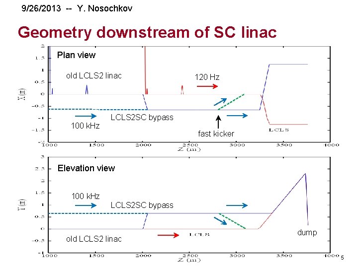
Assumed FEL Configuration • High rep rate beam could be directed to either of two undulators HXR or SXR bunch-by-bunch • 120 Hz beam could be directed to the HXR at separate times • The SC linac would be located in Sectors 0 -10 and would be transported to BSY in the 2 km long Bypass Line. It would use a dual stage bunch compressor. • A dechirper might be used to further cancel energy spread for greater flexibility in beam parameters • The high rep rate beam energy would be 4 Ge. V and the HXR would fill the LCLS hall with ~144 m while the SXR would be <75 m so that it could be fit into ESA • Both undulators would need to support self-seeding as well as other seeding upgrades Insert Presentation Title in Slide Master 17
Undulator Requirements: 1. SXR self-seeding operation between 0. 2 and 1. 3 ke. V in ESA tunnel (<75 meters) with 2. 5 to 4 Ge. V beam 2. HXR self-seeding operation between 1. 3 and 4 ke. V in LCLS tunnel (~144 meters) with 4 Ge. V beam 3. HXR SASE operation up to 5 ke. V with 4 Ge. V beam 4. Primary operation of SXR and TXR at constant beam energy large K variation 5. HXR operation comparable to present LCLS with 2 to 15 Ge. V beam Insert Presentation Title in Slide Master 18
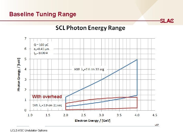
Baseline Tuning Range With overhead LCLS-IISC Undulator Options
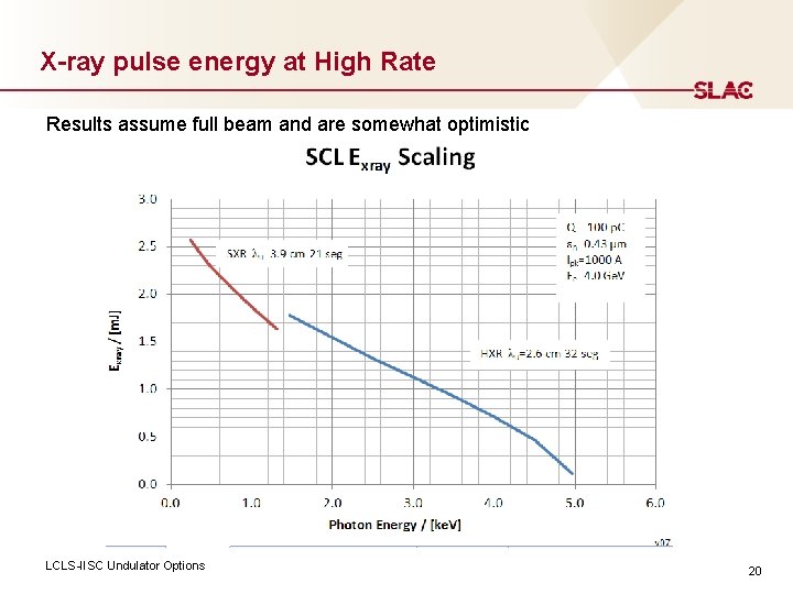
X-ray pulse energy at High Rate Results assume full beam and are somewhat optimistic LCLS-IISC Undulator Options 20
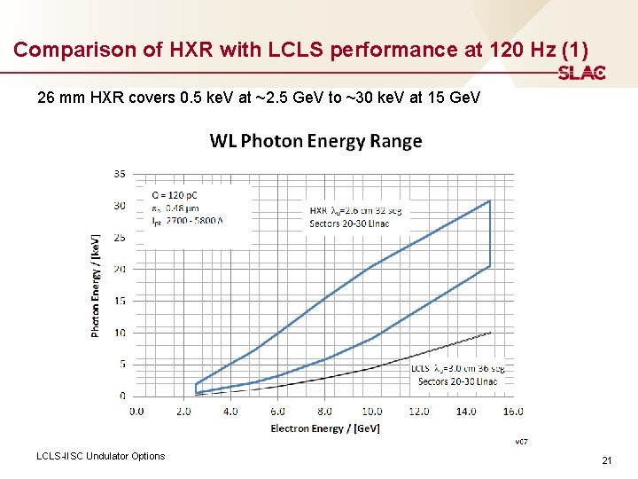
Comparison of HXR with LCLS performance at 120 Hz (1) 26 mm HXR covers 0. 5 ke. V at ~2. 5 Ge. V to ~30 ke. V at 15 Ge. V LCLS-IISC Undulator Options 21
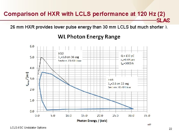
Comparison of HXR with LCLS performance at 120 Hz (2) 26 mm HXR provides lower pulse energy than 30 mm LCLS but much shorter l LCLS-IISC Undulator Options 22
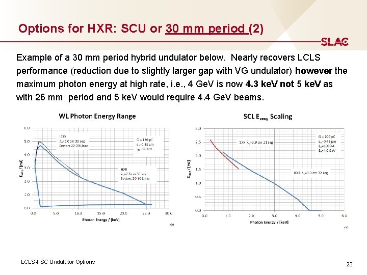
Options for HXR: SCU or 30 mm period (2) Example of a 30 mm period hybrid undulator below. Nearly recovers LCLS performance (reduction due to slightly larger gap with VG undulator) however the maximum photon energy at high rate, i. e. , 4 Ge. V is now 4. 3 ke. V not 5 ke. V as with 26 mm period and 5 ke. V would require 4. 4 Ge. V beams. LCLS-IISC Undulator Options 23
Superr. Conducting Undulator options An SCU has a number of benefits: 1. Would attain comparable performance as LCLS even while achieving 5 ke. V at 4 Ge. V at high rate by operating with high K 2. Would allow shorter SXR period to reduce SXR beam energy and gain length to ensure space in ESA while still covering full wavelength range at constant energy. Insert Presentation Title in Slide Master 24
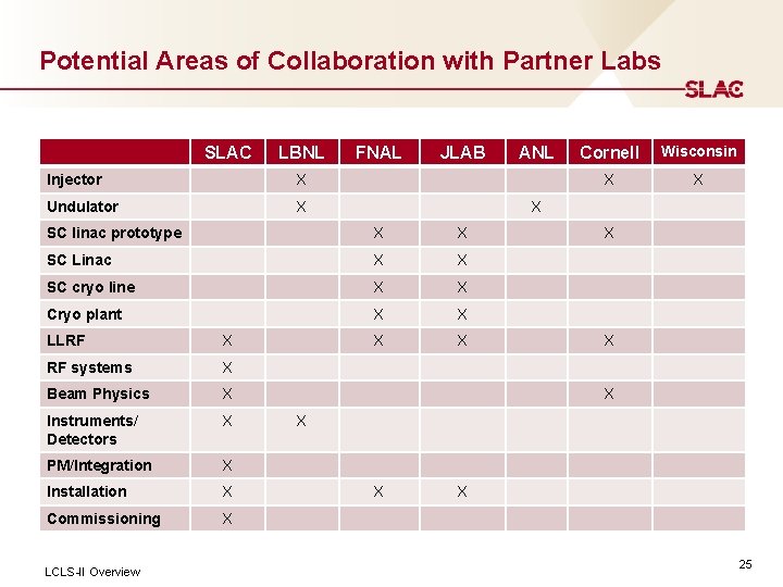
Potential Areas of Collaboration with Partner Labs SLAC LBNL Injector X Undulator X FNAL JLAB X X SC Linac X X SC cryo line X X Cryo plant X X X X X RF systems X Beam Physics X Instruments/ Detectors X PM/Integration X Installation X Commissioning X LCLS-II Overview Cornell Wisconsin X X X SC linac prototype LLRF ANL X X X X 25
Points of Contact Insert Presentation Title in Slide Master 26
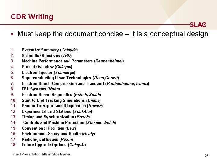
CDR Writing • Must keep the document concise – it is a conceptual design 1. 2. 3. 4. 5. 6. 7. 8. 9. 10. 11. 12. 13. 14. 15. 16. 17. 18. Executive Summary (Galayda) Scientific Objectives (TBD) Machine Performance and Parameters (Raubenheimer) Project Overview (Galayda) Electron Injector (Schmerge) Superconducting Linac Technologies ( Ross, Corlett) Electron Bunch Compression and Transport (Raubenheimer, Emma) FEL Systems (Nuhn) Electron Beam Diagnostics (Frisch, Smith) Start-to-End Tracking Simulations (Emma) Photon Transport and Diagnostics (Rowen) Experimental End-Stations (Schlotter) Timing and Synchronization (Frisch) Controls and Machine Protection (Shoaee, Welch) Conventional Facilities (Law) Environment, Safety and Health (Healy) Radiological Issues (Rokni) Future Upgrade Options (Galayda) Insert Presentation Title in Slide Master 27
- Slides: 27