LCD and Keyboard Interfacing Describe the LCD interfacing

LCD and Keyboard Interfacing “Describe the LCD interfacing and keyboard interfacing”

Objectives Describe the functions of the pins of a typical LCD Interface a LCD to the PIC 18 Describe the key press Interface a Keypad to the PIC 18

Why we use LCD? The declining prices of LCDs The ability to display numbers, charaters and graphics Incorporation of a refreshing controller into the LCD, thereby relieving the CPU of the task of refreshing the LCD Ease for programming for characters and graphics

LCD Screen LCD screen consists of two lines with 16 characters each Every character consists of 5 x 8 or 5 x 11 dot matrix

Pin Symbol I/O Description 1 VSS -- Ground 2 VCC -- +5 V Power Supply 3 VEE -- Power Supply to Control Contrast 4 RS I RS=0 to Select Command Register RS =1 to Select Data Register 5 R/W I R/W=0 for Write R/W=1 for Read 6 E I/O Enable 7 DB 0 I/O The 8 -bit Data Bus 8 DB 1 I/O The 8 -bit Data Bus 9 DB 2 I/O The 8 -bit Data Bus 10 DB 3 I/O The 8 -bit Data Bus 11 DB 4 I/O The 8 -bit Data Bus 12 DB 5 I/O The 8 -bit Data Bus 13 DB 6 I/O The 8 -bit Data Bus 14 DB 7 I/O The 8 -bit Data Bus
 RS = 0: The instruction command code is selected, allowing the")
RS (Register Select) RS = 0: The instruction command code is selected, allowing the user to send command such as clear display, cursor at home RS = 1: The data register is selected , allowing the user to send data to be displayed on the LCD
 R/W = 0: Write information to the LCD R/W = 1: Read")
R/W (Read/Write) R/W = 0: Write information to the LCD R/W = 1: Read information from the LCD
 To latch information presented to its data pins When data is supplied")
E (Enable) To latch information presented to its data pins When data is supplied to data pins, a HIGH-to-LOW pulse must be applied to the E pin in order for the LCD to latch in the data present at the data pins This pulse must be a minimum of 450 n. S wide

LCD Memory LCD display contains three memory blocks: ◦ DDRAM - Display Data RAM ◦ CGRAM - Character Generator RAM ◦ CGROM - Character Generator ROM
 CGROM memory contains default character map")
LCD Memory (cont’d) CGROM memory contains default character map

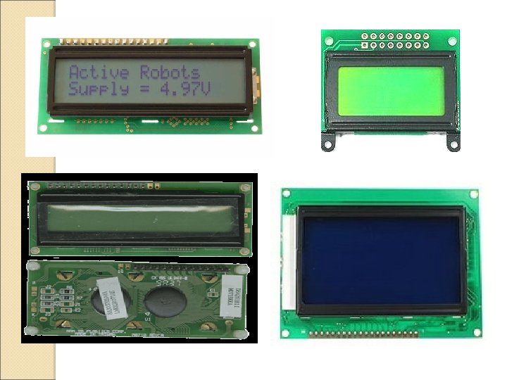
LCD Connections Model with backlights Model without backlights

LCD Operation There are two ways to send characters to LCD: ◦ Delay method (Please see Program 12 -1, pg 476) ◦ Monitoring busy flag (Please see Program 12 -2, pg 477) Use RS = 0 & R/W = 1 to read the busy flag bit to see if the LCD is ready to receive information.

Cursor Address for Some LCDs 80 81 82 83 84 85 86 87 88 89 8 A 8 B 8 C 8 D 8 E 8 F C 0 C 1 C 2 C 3 C 4 C 5 C 6 C 7 C 8 C 9 CA CB CC CD CE CF 16 X 2 LCD

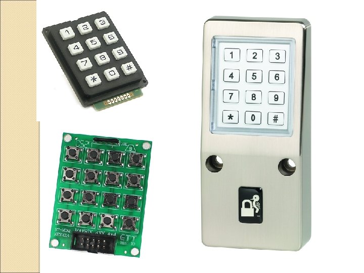
Interfacing the Keyboard to the PIC 18 Organized in a matrix of rows and coloums The CPU accesses both rows and coloums thru’ port; therefore with 8 -bit ports, an 8 X 8 matrix of keys can be connected to a microcontroller Key pressed: Row and column make a contact Key press detection method: 1) Interrupt method 2) Scanning method
 Row (RB 0")
Interrupt Method of Key Press Detection Column (RB 4 -RB 7) Row (RB 0 -RB 3) 4 X 4 Matrix Keyboard Connection to Ports

Keyboard Debounce Noise Stable

Example 1: Identify the row and column of the pressed key for the following: RB 3 -RB 0 = 1110 (Row) RB 7 -RB 4 = 1011 (Column) Try This: Solution: Key number 2 RB 3 -RB 0 = 1101 (Row) RB 7 -RB 4 = 1011 (Column) * Please see Program 12 -4 page 490 for more details

“I hear and I forget. I see and I remember. I do and I understand” END OF CHAPTER
- Slides: 20