LBNL Test Cryostat Preliminary Design Review Tuning Field

LBNL Test Cryostat Preliminary Design Review Tuning – Field Correction Soren Prestemon, Diego Arbelaez, Heng Pan, Scott Myers, Taekyung Ki

Outline • Existing cryostat review – Structure and capacities – Features of each main part – Recent cooling down test results • The extended system – Extension details This is new, to be “reviewed”

The Existing Tuning Cryostat v Structures • Vacuum Chamber • Thermal Shields Assembly ü Tower shields ü Main horizontal shields and flexible connections • Suspension System ü Shields supports ü Cold mass supports • Binary Current Leads (Copper + HTS) ü Three rated current leads which carry 30 A, 100 A, and 500 A • Instrumentation

The Existing Tuning Cryostat v Structures overview PT 415 Cryocooler Instrumentation port Cold mass support (vertical) Thermal shields supports Plus wire feed-in Cold mass support (horizontal) Instrumentation port
 Tower shielding")
The Existing Tuning Cryostat v Structures overview Cold box support Assembly (vertical) Tower shielding Main shielding Existing Magnet assembly

The Existing Tuning Cryostat v Features • The existing cryostat is a conduction-cooled system with two cryocoolers (cryogen-free system). • The cold mass could work at 4. 5 K~40 K with adjustable heaters. • Thermal shields will work at around 50~60 K. • The existing cryostat has a designed heat load of < 2 W at 4. 5 K, additional heat will apply to tune the operation temperature from 20 K~40 K.
 60")
The Existing Tuning Cryostat v Overall heat load Item 300 K-60 K (W) 60 K-4. 2 K (W)* Current leads (total) 52 1. 08 (HTS leads) Radiation load 11 0. 06 Shields supports (total) 0. 55 - Magnets supports (total) 0. 72 0. 3 Instrumentation wires (total) 0. 56 0. 05 total 68. 83 1. 49 30% contingency 84. 27 1. 94 • *this column just shows the designed heat load for the existing cryostat, does not apply for the 20 K~40 K application. • The current leads include one pair of 500 A, one pair of 100 A and two pairs of 30 A. • The cooling capacity of PT 415 is 40 W@45 K and 1. 5 W@4. 2 K.

The Existing Tuning Cryostat v Vacuum Chamber PT 415 Cryocooler A PT 415 Cryocooler B (remote motor) Shields supports tubes Tooling windows Operation vacuum is 10 -7 -10 -6 torr Plus wire feed-in port

The Existing Tuning Cryostat v Thermal Shields Assembly • Consists of tower shields, a main shield, thermal interception accessories, all of which are made of OFHC copper. • Designed working temperature is 50~60 K. • Flexible connections are adopted to connect the tower shields and the main shield. • 45 layers of MLI superinsulation are applied on the outer surfaces; one layer of Mylar is attached to the inner surfaces to reduce the emissivity.

The Existing Tuning Cryostat v Thermal Shields Assembly Copper lead thermal interceptions Tower shields 45 layers of MLI blankets Main shield

The Existing Tuning Cryostat v Thermal shields thermal analysis q Assumptions: ØRadiation load: 11 W; ØConduction heat of 53. 2 W. Ø 1 st stage cold head is 55 K Calculated ΔT = 11 K q The test result (without the load of current leads ) is ΔT=3 K

The Existing Tuning Cryostat v Cold mass suspension system • Consists of vertical and horizontal supports: – Vertical support s are to load the entire cold mass; – Horizontal supports are to do the cold mass alignment. • The vertical supports are designed to be able to load 300 lbs. • Both types of the supports have very low heat leaks. Formed bellows Warm end Stainless steel tube Vertical supports Horizontal supports Release hole for epoxy G 10 rod 316 steel connection Cold mass cooling box Release hole for epoxy G 10 rod Steel stud for G 10 rod (G 10 rod is inserted to the stud and glued by epoxy) Cold end Bracket connected to “cold box” (old design) Existing Cold Mass Assembly G 10 bracket

The Existing Tuning Cryostat v Cold mass suspension system • Assume the cold end is 4. 5 K. • The heat leak through each vertical support is 0. 1 W, the heat through the horizontal support is 0. 05 W. Vertical supports Horizontal supports

The Existing Tuning Cryostat v Binary current leads Copper lead • There are three rated current leads: 500 A, 100 A and 30 A. • All of the current leads consist of traditional copper leads (RRR=30 ) and HTS leads. • The size of copper leads have been optimized for the minimum heat leak(for 500 A lead, the minimum heat leak at full current is 21 W, 15. 7 W with zero current). Thermal interception HTS leads

The Existing Tuning Cryostat v Instrumentation • Monitor temperatures, vacuum, voltages, and status of compressors • Extendable GPIB Bus for all of the measurements. Main GUI Labview based program has been developed for monitoring and recording data. Compressor GUI

The Existing Tuning Cryostat v Cooling down test Heat load : ~ 1. 1 W Location Temperature Regular 2 nd stage 4. 0 ~ 4. 1 K Regular 1 st stage 35 K Thermal shield 32 ~ 34 K Remote 2 nd stage 12. 7 ~ 12. 8 K Remote 1 st stage 29. 9 ~ 30 K Remote cooler being repaired by Cryomech.

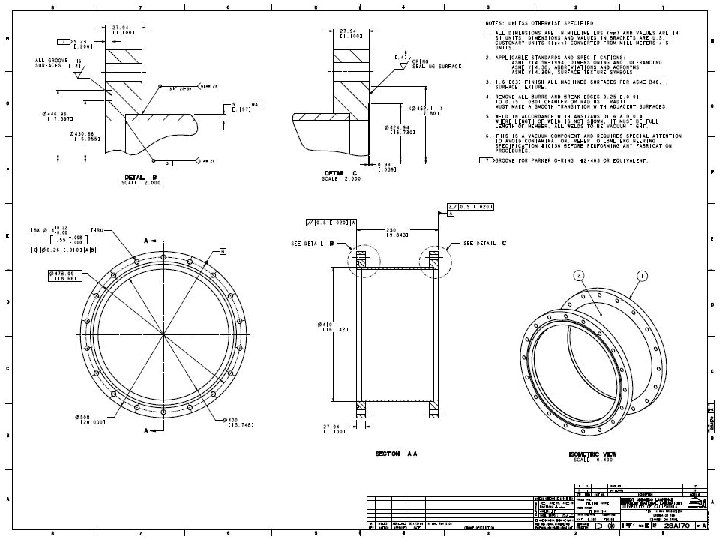
The Proposed Extended Cryostat v Shielding extending The original end flanges will remain The New Extension spool • The main shield can be extended with two extension spools at both ends. • The extensions will NOT affect thermal performance.

The Proposed Extended Cryostat v Shielding extending Extension shielding Bolt connections The overall length of new shields is about 77. 1 in

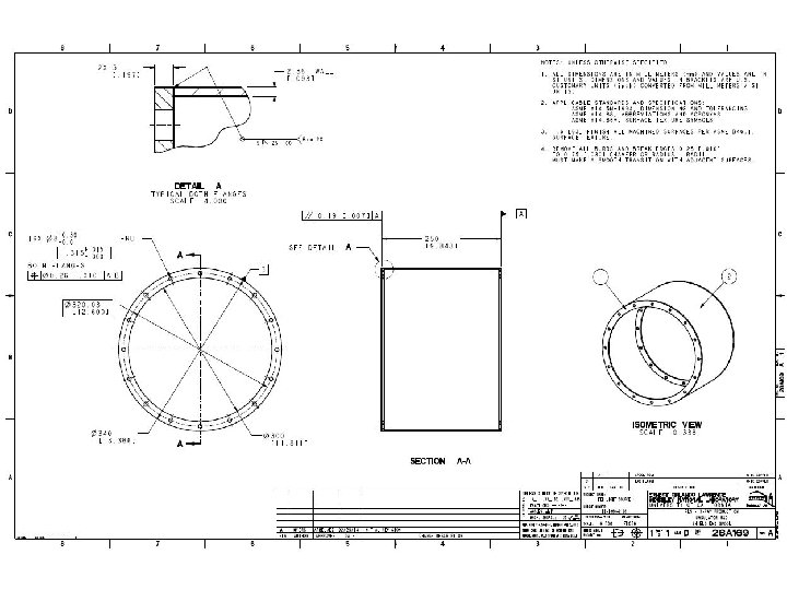
The Proposed Extended Cryostat v Vacuum chamber extending The original vacuum chamber The original end flanges will remain Extension spool

Application of Cryostat to Central Field Corrector Development and Testing • Small scale testing of undulator tuning system will begin in the cryostat in its current configuration – – 100 A current leads Temperature operation from 4. 5 K to ~ 40 K Instrumentation ports for heater switches and temperature sensors Field measurements with pulsed wire method (local measurements at fixed point with hall probe) • Extended cryostat will be used to qualify the full length correctors for use in the ANL cryostat – Will accommodate lengths exceeding the ANL cryostat vacuum chamber – Support system can accommodate the vacuum chamber length and has ample load capacity for the chamber and corrector weight
- Slides: 22