Lathe Operations 1 Introduction A lathe is one


 Bed 2) Head stock 3) Tail stock 4)")


 b) c) d) e) Saddle – The base of the carriage is")


 � v = cutting speed �")


- Slides: 35
Lathe Operations 1
Introduction � A lathe is one of the oldest & most important machine tools ever developed. The job to be machined is rotated & the cutting tool is moved relative to the job. That is why, It’s also called as “ Turning Machine”. � A Lathe was basically developed to machine cylindrical surfaces. But many other operations can also be performed on lathes. e. g. -facing, parting, necking, knurling, taper turning & forming. � A lathe is called the mother of the entire machine tool family. � The lathe can be defined as a machine tool which holds the work between two rigid & strong centres, or in a chuck or face plate while the latter revolves. � The cutting tool is rigidly held & supported in a tool post & feed against the revolving work.
3
Block diagram of center lathe 5
Lathe
Chuck Figure three‑jaw chuck 7
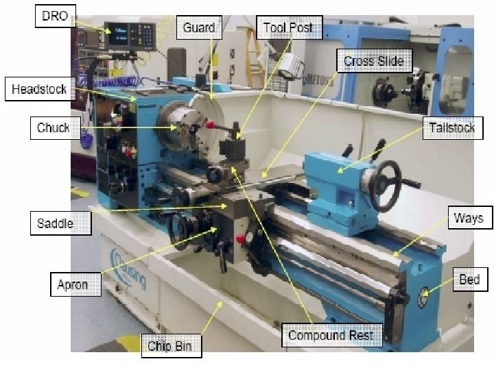
Principle parts of Lathe machine 1) Bed 2) Head stock 3) Tail stock 4) Carriage – saddle, cross-slide, compound rest, tool post, apron 5) Lead Screw
Principle parts of Lathe machine �Bed- - The bed is the base or foundation of the lathe. -It is a heavy & rigid casting made in one piece to resist deflection and vibrations. -It holds or supports all other parts, that is, head stock, tailstock & carriage etc. -The top of the bed is planed to form guides or ways.
Headstock- It is permanently fastened to the left hand end of the lathe. It serves to support the first operative unit of the lathe, i. e. spindle. It’s also called as live centre because it turns with the work. The headstock is that part of the lathe which serves as a housing for the driving pulleys, back gears & spindle. It consist of main parts: 1)Cone pulley, 2)Backgears & lever, 3)Main spindle, 4) Live centre, & 5) Feed reverse lever. Fig. Back Gears
Tailstock It’s on the other end of the bed from the headstock. It’s chief function is to hold the dead centre so that long work pieces can be supported between centres.
Lathe Spindle 12
• Carriage – In between the headstock & tailstock is the carriage. It’s movable on the bed ways and it’s purpose is to hold the cutting tool & to impart to it either longitudinal or cross feed. It has five major parts: a) Saddle b) Cross slide c) Compound rest d) Tool post e) Apron
Carriage a) b) c) d) e) Saddle – The base of the carriage is the saddle which slides along the ways of the lathe bed and supports the cross-slide, compound rest & tool post. Cross slide – It’s mounted on top of saddle. It provides cutting tool motion which is perpendicular to the centre line of the lathe itself. The cross feed movement may be controlled by manual or by power feed. Compound rest– It’s also known as tool rest. It’s mounted on top of the cross-slide. It has a graduated circular base & can be swiveled around a vertical axis. It can be clamped to remain at any angular setting. Tool post- It is mounted on the compound rest & slides in a Tslot. Cutting tool/ tool holder is firmly held in it. Apron – It’s the hanging part in front of the carriage. It is secured underneath the saddle & hangs over the front of the bed. It contains the gear, clutches, & levers for operating the carriage by hand power feeds.
Lead Screw
Lathe Machine
17
18
19
20
Turning Parameters Illustrated Turning operation 21
3. Taper turning 22
23
4. Contour Turning Instead of feeding the tool parallel to the axis of rotation, tool follows a contour that is not necessarily straight (thus creating a contoured form). Figure (c) contour turning 24
5. Boring 25
6. Drilling 26
7. knurling 27
8. Chafering 28
9. Parting off 29
10. Grooving 30
11. Forming 31
12. Threading 32
Machining Calculations: � Spindle Speed - N (rpm) � v = cutting speed � Do = outer diameter � Feed Rate - fr (mm/min -or- in/min) � f = feed per rev � Depth of Cut - d (mm/rev -or- in/rev) � Do = outer diameter � Df = final diameter � Machining Time - Tm 33 � L = length of cut Dept. Mechanical Engg. PC Poly (min)
34
35