Latches and flipflops Latches A latch is a


- Slides: 14

Latches and flip-flops

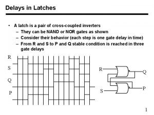
Latches A latch is a temporary storage device that has two stable states (bistable). It is a basic form of memory. The S-R (Set-Reset) latch is the most basic type. It can be constructed from NOR gates or NAND gates. With NOR gates, the latch responds to active-HIGH inputs; with NAND gates, it responds to active-LOW inputs. R S Q Q NOR Active-HIGH Latch S R Q Q NAND Active-LOW Latch

Latches The active-HIGH S-R latch is in a stable (latched) condition when both inputs are LOW. Assume the latch is initially RESET (Q = 0) and the inputs are at their inactive level (0). To SET the latch (Q = 1), a momentary HIGH signal is applied to the S input while the R remains LOW. To RESET the latch (Q = 0), a momentary HIGH signal is applied to the R input while the S remains LOW. 0 R 1 0 0 1 0 S 0 R 1 0 0 S Q Latch initially RESET Q Q Latch initially SET Q

Latches The active-LOW S-R latch is in a stable (latched) condition when both inputs are HIGH. Assume the latch is initially RESET (Q = 0) and the inputs are at their inactive level (1). To SET the latch (Q = 1), a momentary LOW signal is applied to the S input while the R remains HIGH. To RESET the latch a momentary LOW is applied to the R input while S is HIGH. Never apply an active set and reset at the same time (invalid). 1 S 1 R 1 S 1 0 1 0 Q Latch initially RESET Q Q Latch initially 1 SET 0 1 R Q

Latches Truth table for active low S-R latch Output waveform (Assume that Q is initially LOW)

Gated S-R latch A gated latch is a variation on the basic latch. S The gated latch has an additional input, called enable (EN) that must be HIGH in order for the EN latch to respond to the S and R inputs. Show the Q output with R relation to the input signals. Assume Q starts LOW. Keep in mind that S and R are only active when EN is HIGH. S R EN Q Q Q

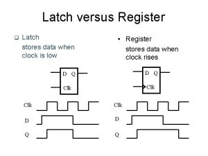
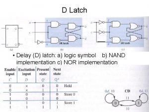
The Gated D Latch The D latch is an variation of the S-R latch but combines the S and R inputs into a single D input as shown: D Q EN Q A simple rule for the D latch is: Q follows D when the Enable is active. Q

The Gated D-Latch The truth table for the D latch summarizes its operation. If EN is LOW, then there is no change in the output and it is latched.

The Gated D-Latch D Determine the Q output for the D latch, given the inputs shown. Q EN Q Notice that the Enable is not active during these times, so the output is latched.

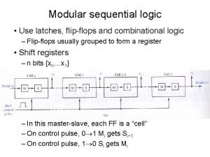
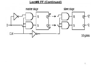
Edge-Triggered Flip-Flops A flip-flop differs from a latch in the manner it changes states. A flip-flop is a clocked device, in which only the clock edge determines when a new bit is entered. The active edge can be positive or negative. Dynamic input indicator

D Flip-Flops The truth table for a positive-edge triggered D flip-flop shows an up arrow to remind you that it is sensitive to its D input only on the rising edge of the clock; otherwise it is latched. The truth table for a negative-edge triggered D flip-flop is identical except for the direction of the arrow. (a) Positive-edge triggered (b) Negative-edge triggered

J-K FLIP-FLOPS The J-K flip-flop is more versatile than the D flip flop. In addition to the clock input, it has two inputs, labeled J and K. When both J and K = 1, the output changes states (toggles) on the active clock edge (in this case, the rising edge).

J-K FLIP-FLOPS Q J CLK Determine the Q output for the J-K flip-flop, given the inputs shown. K Notice that the outputs change on the leading edge of the clock. Set CLK J K Q Toggle Set Latch Q

Asynchronous Preset and Clear inputs Synchronous inputs are transferred in the triggering edge of the clock (for example the D or J-K inputs). Most flip-flops have other inputs that are asynchronous, meaning they affect the output independent of the clock. PRE Two such inputs are normally labeled preset (PRE) and clear (CLR). These inputs are usually active LOW. A J-K flip flop with active LOW preset and CLR is shown. Q J CLK Q K CLR
 Shallow latch vs deep latch
 Standard logic latches
 Flipflops
 D latch
 What is the difference between latches and flip flops
 Tabella verità flip flop jk
 Nmos
Nmos Latch s-r
 D latch and d flip flop
 Latch and unlatch ladder logic
 Difference between latch and flip flop
 Truth table of sr flip flop
 Cicq
Cicq Latch timing problem
 Circuitos sequenciais exercícios resolvidos

