Latches and Flip Flops Latches A latch is


 Latch")
 denotes the present state of a memory device,")


 from its")


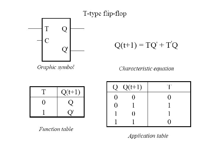
 Flip Flop • A T flip-flop is obtained from a JK flipflop")
- Slides: 21
Latches and Flip Flops
Latches • A latch is a bistable device, with inputs, that remains in a given state as long as power is applied and until input signals are applied to cause its output to change. • A bistable device is a circuit having two stable conditions (states).
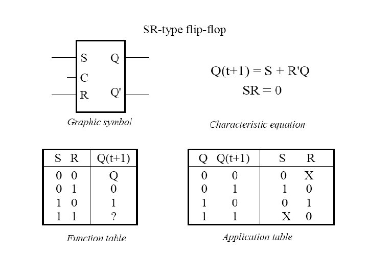
SR (set-Reset) Latch
Next State • Q or Q(t) denotes the present state of a memory device, i. e. , the state at the time the input signals are applied, • Q+ or Q(t+1) denotes the next state, i. e. , the new state assumed by the device in response to the input signals.
Gated SR Latch
Gated D Latch
Timing considerations • Propagation delays • Minimum pulse width • Setup and hold time
Setup and hold times • To achieve a satisfactory operation of a gated latch, constraints are normally placed on the time intervals between input changes. • The minimum time the input signal must be held fixed before and after the latching action is called the setuptime and holdtime, respectively.
Minimum pulse width • The minimum amount of time a signal must be applied in order to produce a desired result.
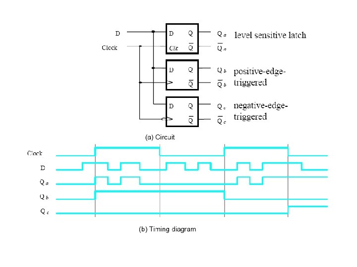
Latches vs. Flip Flops • • Latches are flip-flops for which the timing of the output changes are not controlled. • For a latch, the output responds immediately to changes on the input lines. i. e the timing of output changes are not controlled. • A flip-flop is designed to change its output at the edge of a controlling clock signal.
Positive/Negative Edge Triggering • The transition of a control signal (clock pulse) from its low to high value (0 to 1) in positive logic is called the positive edge of the control signal, while the transition from high to low (1 to 0) is called the negative edge. • flip-flops are designed to change their output at the either the positive or negative edge of a clock signal.
Edge triggered Flip Flops • Edge triggered flip-flops use just one of the edges of the clock pulse to affect the reading of the input lines. • These flip-flops are designed to be triggered by either the positive or negative edge. • In analyzing the behavior of an asynchronous sequential circuit, one often needs to know which edge trigger the flip-flops used.
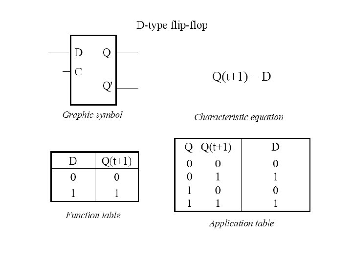
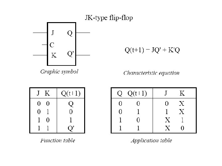
Flip Flops • There are four different types of flip-flops: SR, D, JK, and T types.
JK Flip Flop • A JK flip-flop works just like an SR flip-flop if we consider J input as S(et) input and K input as R(eset) input, except when both S and R inputs are set to 1, the output simply flips over.
JK Flip Flops
T (toggle) Flip Flop • A T flip-flop is obtained from a JK flipflop by tying the J and K inputs together to form the T inpu