LATCHED FLIPFLOPS AND TIMERS INTRODUCTION Latches and flipflops


- Slides: 36

LATCHED, FLIP-FLOPS, AND TIMERS

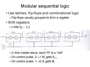
INTRODUCTION • Latches and flip-flops are the basic single-bit memory elements used to build sequential circuit with one or two inputs/outputs, designed using individual logic gates and feedback loops. • Latches: – The output of a latch depends on its current inputs and on its previous output and its change of state can happen at any time when its inputs change. • Flip-Flops: – The output of a flip-flop also depends on current inputs and its previous output but the change of state occurs at specific times determined by a clock input.

INTRODUCTION • Latches: – S-R Latch – Gate D-Latch • Flip-Flops: – Edge-Triggered Flip-Flop (S-R, J-K, D) – Asynchronous Inputs – Master-Slave Flip-Flop – Flip-Flop Operating Characteristics – Flip-Flop Applications – One-shots & The 555 Timer

An Active High Input S-R (Set – Reset) Latch

An Active Low Input (Set – Reset) Latch

EXAMPLE If the waveform in figure below are applied to the inputs of the active LOW input latch, determine the waveform that will be observed on the Q output. Assume that Q is initially LOW.

The Gated S-R (Set – Reset) Latch · A gate input is added to the S-R latch to make the latch synchronous. · A gated latches requires input, EN. · In order for the set and reset inputs to change the latch, the gate input must be active (high/Enable). · When the gate input is low, the latch remains in the hold condition.

Example: The Gated S-R (Set – Reset) Latch Determine the Q output waveform if the inputs in figure below are applied to a gated D latch, which is initially RESET

The Gated D Latch · The D (data) latch has a single input that is used to set and to reset the flip-flop. ·When the gate is high, the Q output will follow the D input. ·When the gate is low, the Q output will hold.

The Gated D Latch (74 LS 75)

EXAMPLE Determine the Q output waveform if the inputs shown in figure below are applied to a gated D latch, which is initially RESET

Edge Triggered Flip-Flops • An edge triggered flip-flop changes state either at the positive edge (rising edge) or at the negative edge (falling edge) of the clock pulse and is sensitive to its inputs only at this transition of the clock. • Can be either positive edge triggered (no bubble at C input) or negative edge triggered (bubble at C input).

Clock Signals & Synchronous Sequential Circuits 1 Clock signal 0 Rising edges of the clock (Positive-edge triggered) Falling edges of the clock (Negative-edge triggered) Clock Cycle Time • A clock signal is a periodic square wave that indefinitely switches values from 0 to 1 and 1 to 0 at fixed intervals.

Operation of a positive edge-triggered S-R flip-flop The S and R inputs of the S-R flip flop are called synchronous input because data on these inputs are transferred to the flip flop’s output only on the triggering edge of the clock pulse.

Truth Table for a positive edge-triggered S-R flip-flop

EXAMPLE Determine the output waveforms of the flip-flops in figure below for S, R, and CLK inputs. Assume that the positive edge triggered flip flops is initially RESET.

A positive edge-triggered D flip-flop formed with an S-R flip-flop and an inverter

EXAMPLE Given the waveforms in figure below for the D input and the clock, determine the Q output waveform if the flip flops starts out RESET.

Edge-Triggered J-K flip-flop

Edge-triggered J-K flip-flop • The edge-triggered J-K will only accept the J and K inputs during the active edge of the clock. • The small triangle on the clock input indicates that the device is edge-triggered. • A bubble on the clock input indicates that the device responds to the negative edge. no bubble would indicate a positive edge-triggered device.

Transitions illustrating the toggle operation when J =1 and K = 1

EXAMPLE (Positive Edge Triggered) The waveform in figure below are applied to the flip flop as shown. Determine the Q output, starting in the RESET state.

EXAMPLE (Negative Edge Triggered) The waveforms in figure below are applied to the J, K, and clock inputs as indicated. Determine the Q output, assuming that the flip flop is initially RESET.

Logic symbol for a J-K flip-flop with active-LOW preset and clear inputs. An active level on the preset input will set the flip flop, and an active level on the clear input will reset it. These input affect the state of the flip flop independent of the clock.

Logic diagram for a basic J-K flip flop with active LOW preset and clear inputs

EXAMPLE For the positive edge triggered J-K flip flop with preset and clear inputs in figure below, determine the output Q for the input shown in the timing diagram if Q is initially LOW.

Flip-flops used in a basic register for parallel data storage

Frequency Division (J-K flip-flop as a divide-by-2 device. Q is one-half the frequency of CLK)

Two J-K flip-flops used to divide the clock frequency by 4. QA is one-half and QB is one-fourth the frequency of CLK.

EXAMPLE Develop the fout waveform for circuit in figure below when an 8 k. H square wave input is applied to the clock input of the flip flop A.

Flip-flops used to generate a binary count sequence. Two repetitions (00, 01, 10, 11) are shown

EXAMPLE Determine the output waveforms in relation to the clock for QA, QB and QC in the circuit of figure below and show the binary sequence represented by these waveform.

Basic operation of a 555 Timer • • • Threshold Control Voltage Trigger Discharge Reset Output

Functional Diagram of 555 Timer • Monostable (one-shot) operation • Astable operation

Monostable (one-shot) operation tw=1. 1 R 1 C 1

Monostable (one-shot) operation
 Flipflops
 Flipflops
 The interrupt is an example of edge triggered
 What is the difference between latches and flip flops
 T flip flop
 Conventional cmos latches
 Sr latch
 The 8051 has______16-bit counter/timers
 On delay timer coil symbol
 8051 timers
 Timer in assembly language
 아두이노 타이머 인터럽트 2개
 24 timers mennesket
 Mnemonic code
 Model factory anniken
 Arielle solheim
 Lecturel
 Tmod 8051
 Idle timer expired
 Intro paragraph outline
 Module 5 supply and demand introduction and demand
 An introduction to shakespeare and romeo and juliet part 1
 Essay of advantages and disadvantages
 Introduction to acids and bases webquest
 Famous epic poem by homer
 Introduction to computer organization and architecture
 Romeo and juliet introduction
 The odyssey and epic poetry: an introduction, part 1
 Introduction body and conclusion
 Introduction of system analysis and design
 Nas v san
 Epic rules
 Hook for romeo and juliet
 Romeo and juliet prologue analysis
 Setting of romeo and juliet
 Centralized recruitment
 Report structure
