laser Introduction 2 Maser 3 Laser 4 Ruby

laser

Introduction 2

Maser 3

Laser 4

Ruby Laser : 1960, the first laser

6


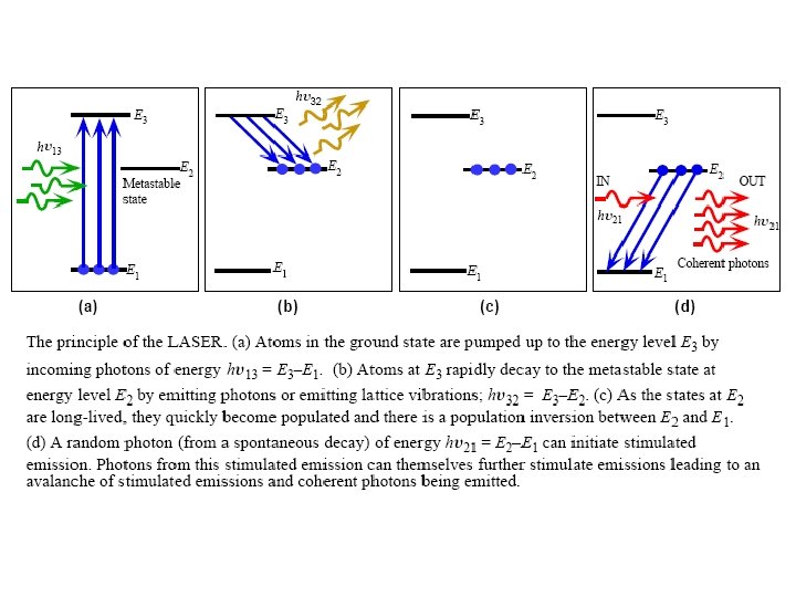
Stimulated Emission and Photon Amplification Light Amplification by Stimulated Emission of Radiation, Laser Spontaneous emission 3 features of stimulated emission : (1) 1 photon in, 2 photons out light amplification (2) emitted photon in the same direction as the incoming photon (3) emitted photon in phase ( coherent ) with the incoming photon Condition of making laser:
 unidirectional (2) high intensity ( Ex : He-Ne")
Characteristics of a laser : (1) unidirectional (2) high intensity ( Ex : He-Ne Suppose: laser : ~ 100 W/m 2 which is ~ N 1 atoms per unit volume with energy E 1 4000 x sunlight ) N 2 atoms ………………. . . E 2 (3) nearly monochromatic Upward transition rate is (4) coherent Downward transition rate is Spontaneous emission Simulated emission B 12, A 21, and B 21 : Einstein coefficients (ρ : photon energy density per unit freq. represents the number of photon with hv)

Ratio of stimulated emission to spontaneous emission : Ratio of stimulated emission to absorption :
 need optical cavity to contain photons need to achieve")
Lasing Requirements: need large ρ(hυ) need optical cavity to contain photons need to achieve N 2> N 1 population inversion from Boltzmann statistics N 2 > N 1 negative T (K) laser based on non-T. E.

The rate R 12 represents the rate at which N 1 is decreasing by absorption The rate R 21 represents the rate at which N 2 is decreasing by spontaneous and stimulated emission Further

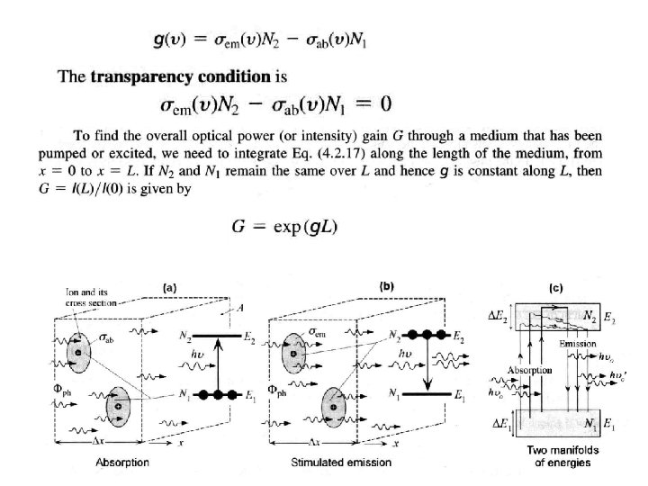
Emission and absorption cross-sections The flux Фph=I/hν: the number of photons flowing per unit area along a certain direction. The absorption of radiation depends on two factors: the number of ions per unit volume N 1 and the interaction of the photon with an individual ion. N 1 ions per unit volume, the total power absorbed per unit volume is Iσab. N 1

The absorption coefficient

Erbium Doped Fiber Amplifier Er 3+ ions doped into the core region of an optical fiber. optical gain, Gop = K ( N 2 –N 1 ) K : a constant depends on pumping intensity drawback 1, E 2 decay spontaneously from E 2 to E 1 which will give rise to unwanted noise. 810 nm Less efficient 2, When not pumped, Er 3+ ions will absorb 1550 nm (from E 1 to E 2). 3, the energy levels are not single unique levels (15251565 nm) Lifetime 10 ms

Er-doped fiber usually inserted into fiber communication line by splicing gain efficiency : 8 -10 d. B/m. W is defined by the maximum optical gain achievable per unit optical pumping power.
")
He-Ne Laser a gaseous mixture of He and Ne atoms ( 5: 1 ) in a gas discharge tube stimulated emission from Ne atoms ( ground state : 1 s 22 p 6 ) He atoms ( ground state : 1 s 2 ) excite Ne atoms by atomic collisions

Diameter increase intensity decreases
")
The ends of the tube are sealed with a flat mirror (99. 9% reflecting) at one end a concave mirror (99%) at the other end. Brewster windows are used at the end to allow only polarized light to be transmitted.

Doppler Broadening

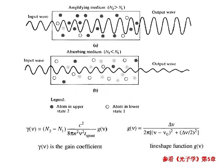
Optical Gain and Cavity Modes from Doppler broadening : optical gain lineshape ~ Gaussian function with typical spread in frequency of 2 -5 GHz FWHM of the optical gain vs. freq. spectrum (assuming Maxwell velocity distribution) : applied nearly to all gas lasers ( solid state lasers have different broadening mechanisms ) For Fabry Perot optical resonator: only cavity certain modes with specified λ can be maintained as standing waves in the cavity

Optical Gain Coefficient

Threshold Gain

Pump Rate and Output Power
")
PRL 110, 206802 (2013)

Phase Condition

Laser Modes 1, simplified ideal analysis : plane wave & perfectly parallel mirrors assumed 2, all practical laser cavities have finite transverse size and not all cavities have flat reflectors at the ends 3, off-axis self-replicating rays can exist non-axial modes greater transverse size more off-axis modes 4, a mode : a particular spatial electric field pattern at one reflector that can replicate itself after one round trip through the cavity
 that are")
All modes can be represented by fields ( E & B ) that are nearly normal to the cavity axis transverse electric and magnetic (TEMpqm) modes p , q number of nodes in the field distribution along y and z ( transverse to the cavity axis x ) m ( longitudinal mode number ) number of nodes along the x-axis, usually very large ( ~ 106 in gas laser ) and not written

Laser Diode

Population Inversion in Homojunction Laser Diode degenerately doped direct bandgap p-n junction diode EFn> Ec, EFp< Ev forward bias with e. V > Eg population inversion at the junction The applied voltage diminishes the builtin potential barrier to almost zero which means that electrons (holes) flow into the SCL and flow over to the p+(n+)-side to constitute the diode current.

In SCL, there are more electrons in the conduction band at energies near Ec than electrons in the valence band near Ev, i. e. there is a population inversion between energies near Ec and those near Ev around the junction. incoming photon hυ = Eg in active region more likely to cause stimulated emission than being absorbed optical gain
 mode of the cavity")
reflectors formed by cleaved surfaces ( ~ 30% reflecting ) mode of the cavity : , ( n : refractive index )
 stimulated")
Threshold Current pumping mechanism: forward diode current at I = Itrans (transparency current) stimulated emission balances counter absorption at I > Ith ( threshold current ) optical gain g reached gth optical gain overcome photon losses from the cavity optical gain reached gth lasing emission Jth in homojunction laser diode is too high for practical uses ( can operate only at very low temp. )
 carrier confinement (2) photon confinement")
Heterostructure Laser Diodes To reduce Ith need better (1) carrier confinement (2) photon confinement improved carrier confinement in DH structure easier to achieve population inversion in narrow Eg active layer Ith↓ narrow Eg semiconductor usually has higher refractive index better photon confinement in narrow Eg active region photon concentration ↑ stimulated emission rate ↑ Ith↓ advantage of the Al. Ga. As DH laser lattice matched to substrate

1. The electrodes are attached to the Ga. As rather than Al. Ga. As for better contacting and avoids Schottky junctions which would limit the current. 2. the n and p-Al. Ga. As layers provide carrier and optical confinement. 3. p-Ga. As layer is the lasing region. The advantage of this W~um, Ith~m. A heterojunction is that there is only a small lattice mismatch and hence negligible strain induced interfacial defects. the advantages of stripe geometry : 1. reduced contact area Ith↓ 2. reduced emission area easier coupling to optical fibers

buried double heterostructure laser diode For the lateral optical confinement of photons increases the rate of stimulated emission and hence the efficiency of the diode buried DH with right dimensions compared with the λ of radiation only fundamental mode can exist single mode laser diode DH Al. Ga. As/Ga. As LD ~ 900 nm LD DH In. Ga. As. P/In. P LD 1. 3/1. 55 μm LD

Output Modes of LD

output spectrum from an index guided LD low current multimode high current single mode spectrum of most gain guided LD remain multimode even at high diode current Temperature Dependence of Ith slope efficiency ηslope : Less than 1 W/A

in single mode LD : when shift of peak gain causes mode change to an adjacent longer λ mode hopping to restrict mode hopping design the device structure to keep modes sufficiently separated

LED and Laser diode

Distributed Bragg Reflector Laser Diode

Distributed Feedback Laser Diode radiation fed from active layer into guiding layer in the whole cavity length corrugated grating periodic refractive index change partially reflected Waves oppositely traveling waves can only coherently coupled to set up a standing wave, a mode, if their frequency is related to the corrugation periodictiy Λ relative threshold gain for higher mode is high only m = 0 mode can effectively lase. Asymmetry introduced by fabrication process or on purpose only one mode appear L >> Λ ( λm λB)

Cleaved-Coupled-Cavity Laser couple two different laser optical cavities only waves that can exist as modes in both cavities are allowed restriction in modes and increase separation between modes single mode operation more easily
 narrow Eg active")
Single Quantum Well Structure very thin ( < 50 nm ) narrow Eg active region sandwiched between wider Eg semiconductors ( Ex. Ga. As/Al. Ga. As SQW : ΔEc > ΔEv ) two-dimensional electron gas confined in the x-direction d << Dy , Dz density of electronic states changes in a steplike fashion

The advantages of QW lasers to DH lasers : 1. lower threshold current (0. 5 -1 m. A to 10 -50 m. A) 2. narrower linewidth in λ advantages of SQW (single quantum well) can be extended by using MQW (multiple quantum well)

Vertical Cavity Surface Emitting Laser Wavelength stability: Wavelength uniformity Temperature sensitivity of wavelength High Temperature Operation Higher power per unit area Manufacturabilty and yield Cost http: //www. princetonoptronics. com/pdf s/Introduction 2 VCSELs. pdf

- Slides: 51