
LABORATORI NAZIONALI DI FRASCATI www lnf infn it
LABORATORI NAZIONALI DI FRASCATI www. lnf. infn. it SHIP Test Beam Oct-Nov 2015 G. Bencivenni LNF-INFN, Italy
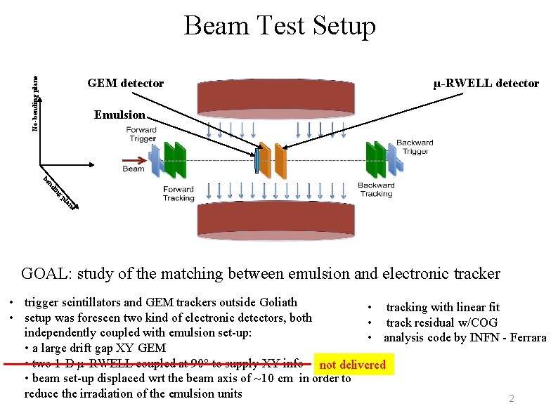
No-bending plane Beam Test Setup GEM detector µ-RWELL detector Emulsion be g in nd pl e an GOAL: study of the matching between emulsion and electronic tracker • trigger scintillators and GEM trackers outside Goliath • tracking with linear fit • setup was foreseen two kind of electronic detectors, both • track residual w/COG independently coupled with emulsion set-up: • analysis code by INFN - Ferrara • a large drift gap XY GEM • two 1 -D µ-RWELL coupled at 90° to supply XY info not delivered • beam set-up displaced wrt the beam axis of 10 cm in order to reduce the irradiation of the emulsion units 2
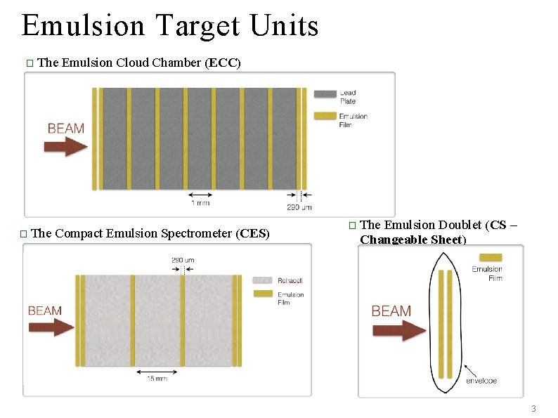
Emulsion Target Units � The Emulsion Cloud Chamber (ECC) Compact Emulsion Spectrometer (CES) � The Emulsion Doublet (CS – Changeable Sheet) 3
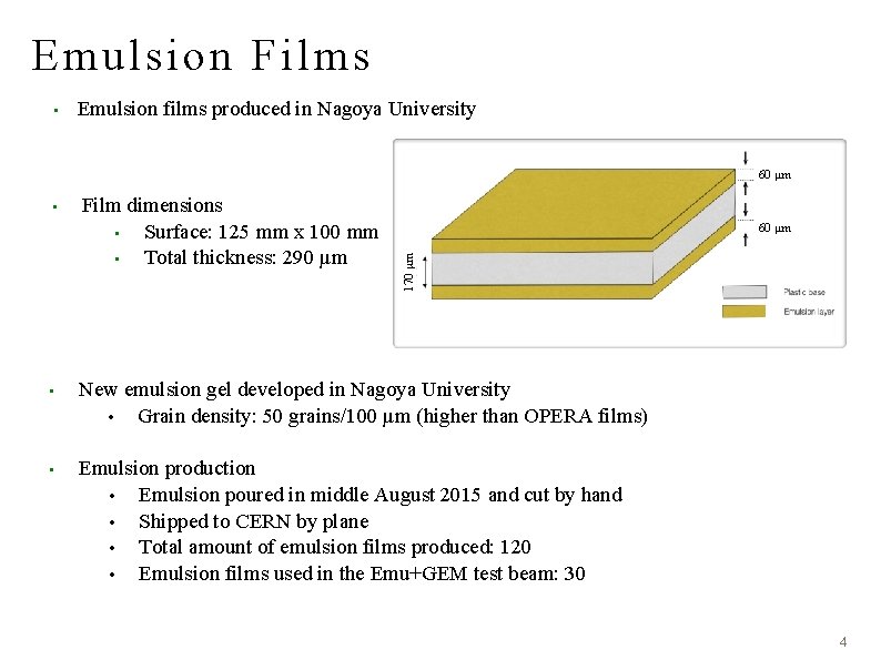
Emulsion Films • Emulsion films produced in Nagoya University 60 μm Film dimensions • Surface: 125 mm x 100 mm • Total thickness: 290 μm 60 μm 170 μm • • New emulsion gel developed in Nagoya University • Grain density: 50 grains/100 μm (higher than OPERA films) • Emulsion production • Emulsion poured in middle August 2015 and cut by hand • Shipped to CERN by plane • Total amount of emulsion films produced: 120 • Emulsion films used in the Emu+GEM test beam: 30 4
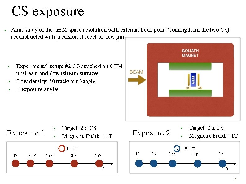
CS exposure Aim: study of the GEM space resolution with external track point (coming from the two CS) reconstructed with precision at level of few µm • • Experimental setup: #2 CS attached on GEM upstream and downstream surfaces Low density: 50 tracks/cm 2/angle 5 exposure angles • Exposure 1 • Target: 2 x CS Magnetic Field: + 1 T. B=1 T 0° 7. 5° 15° 30° Exposure 2 0° 45° θ • 7. 5° 15° • x Target: 2 x CS Magnetic Field: - 1 T B=1 T 30° 45° θ 5
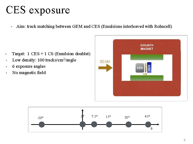
CES exposure • • • Aim: track matching between GEM and CES (Emulsions interleaved with Rohacell) Target: 1 CES + 1 CS (Emulsion doublet) Low density: 100 tracks/cm 2/angle 6 exposure angles No magnetic field -30° 0° 7. 5° 15° 30° 45° θ 6
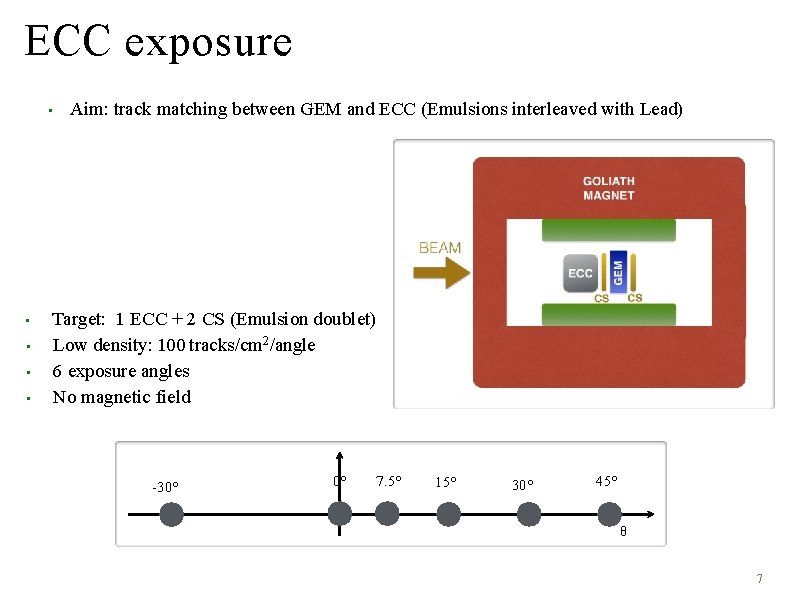
ECC exposure • • • Aim: track matching between GEM and ECC (Emulsions interleaved with Lead) Target: 1 ECC + 2 CS (Emulsion doublet) Low density: 100 tracks/cm 2/angle 6 exposure angles No magnetic field -30° 0° 7. 5° 15° 30° 45° θ 7
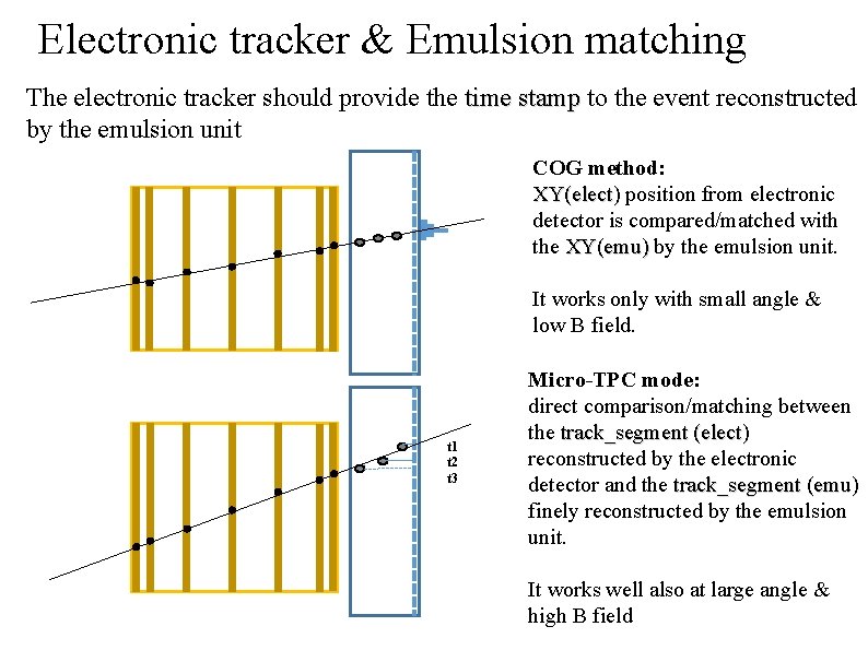
Electronic tracker & Emulsion matching The electronic tracker should provide the time stamp to the event reconstructed by the emulsion unit COG method: XY(elect) position from electronic detector is compared/matched with the XY(emu) by the emulsion unit. It works only with small angle & low B field. t 1 t 2 t 3 Micro-TPC mode: direct comparison/matching between the track_segment (elect) reconstructed by the electronic detector and the track_segment (emu) finely reconstructed by the emulsion unit. It works well also at large angle & high B field
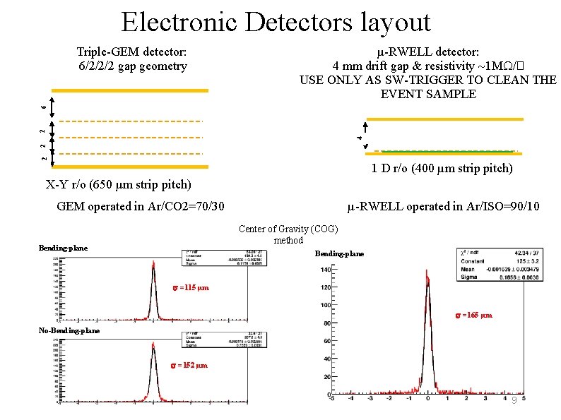
Electronic Detectors layout µ-RWELL detector: 4 mm drift gap & resistivity 1 M /� USE ONLY AS SW-TRIGGER TO CLEAN THE EVENT SAMPLE 2 2 4 2 6 Triple-GEM detector: 6/2/2/2 gap geometry 1 D r/o (400 µm strip pitch) X-Y r/o (650 µm strip pitch) GEM operated in Ar/CO 2=70/30 µ-RWELL operated in Ar/ISO=90/10 Center of Gravity (COG) method Bending-plane =115 µm =165 µm No-Bending-plane =152 µm 9
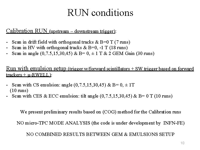
RUN conditions Calibration RUN (upstream – downstream trigger): - Scan in drift field with orthogonal tracks & B=0 T (7 runs) - Scan in HV with orthogonal tracks & B=0, -1 T (18 runs) - Scan in angle (0, 7. 5, 15, 30, 45) & B= 0, ± 1 T & 2 GEM Gain (30 runs) Run with emulsion setup (trigger w/forward scintillators + SW trigger based on forward trackers + µ-RWELL): - Scan with CS emulsion: angle (0, 7. 5, 15, 30, 45) & B= 0, ± 1 T (10 runs) - Scan with CES & ECC emulsion: tilt angle (0, 7. 5, 15, 30, 45) & B= 0 T (10 runs) We present preliminary results based on (COG) method for the Calibration runs NO micro-TPC MODE ANALYSIS (the code is under development by INFN-FE) NO COMBINED RESULTS BETWEEN GEM & EMULSIONS SETUP 10
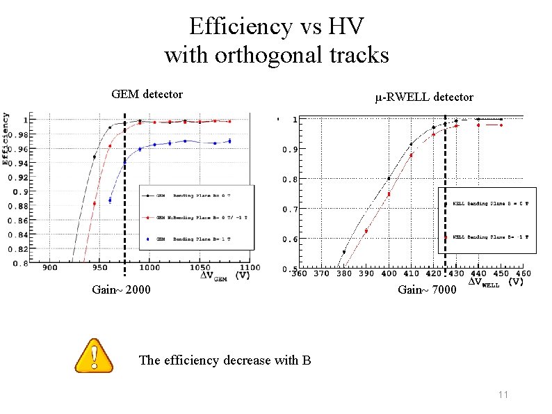
Efficiency vs HV with orthogonal tracks GEM detector Gain 2000 µ-RWELL detector Gain 7000 The efficiency decrease with B 11
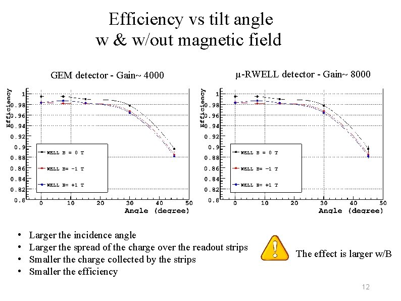
Efficiency vs tilt angle w & w/out magnetic field GEM detector - Gain 4000 • • µ-RWELL detector - Gain 8000 Larger the incidence angle Larger the spread of the charge over the readout strips Smaller the charge collected by the strips Smaller the efficiency The effect is larger w/B 12
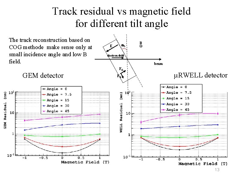
Track residual vs magnetic field for different tilt angle The track reconstruction based on COG methode make sense only at small incidence angle and low B field. GEM detector L E B x electron drift beam FE FB µRWELL detector 13
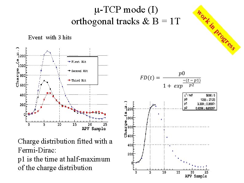
in o pr ss e gr Event with 3 hits rk wo -TCP mode (I) orthogonal tracks & B = 1 T Charge distribution fitted with a Fermi-Dirac: p 1 is the time at half-maximum of the charge distribution
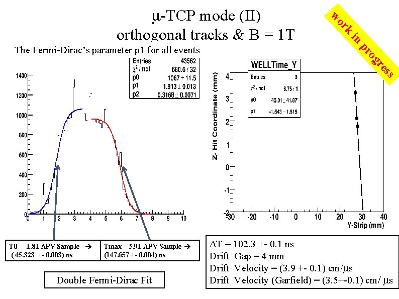
rk in o pr The Fermi-Dirac’s parameter p 1 for all events wo -TCP mode (II) orthogonal tracks & B = 1 T gr s es T 0 = 1. 81 APV Sample ( 45. 323 +- 0. 003) ns Tmax = 5. 91 APV Sample (147. 657 +- 0. 004) ns Double Fermi-Dirac Fit ΔT = 102. 3 +- 0. 1 ns Drift Gap = 4 mm Drift Velocity = (3. 9 +- 0. 1) cm/ s Drift Velocity (Garfield) = (3. 5+-0. 1) cm/ s
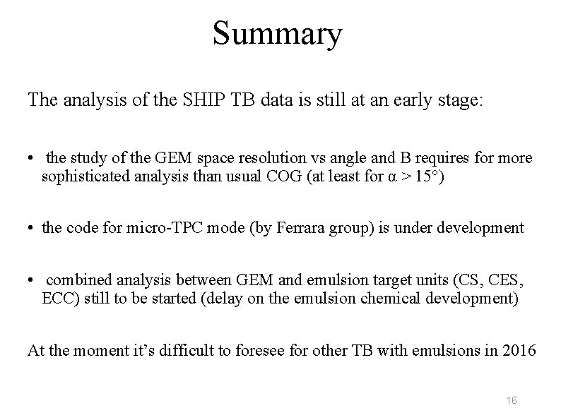
Summary The analysis of the SHIP TB data is still at an early stage: • the study of the GEM space resolution vs angle and B requires for more sophisticated analysis than usual COG (at least for α > 15°) • the code for micro-TPC mode (by Ferrara group) is under development • combined analysis between GEM and emulsion target units (CS, CES, ECC) still to be started (delay on the emulsion chemical development) At the moment it’s difficult to foresee for other TB with emulsions in 2016 16
2016 Beam Time request In the framework of µ-RWELL R&D we are collaborating with the CMS – phase 2 upgrade group for the design & construction of a first prototype of large area µ-RWELL with the so called LR resistive scheme (see Morello presentation of today). The goal is to have a dedicated TB of such a proto by the end of the 2016 (last H 4 TB time slot). In parallel we also aim to test some small (10 x 10 cm 2) µ-RWELL protos with other features (such as HR resistive scheme and thicker WELL amplification stage – 125µm ) 17
SPARES 18
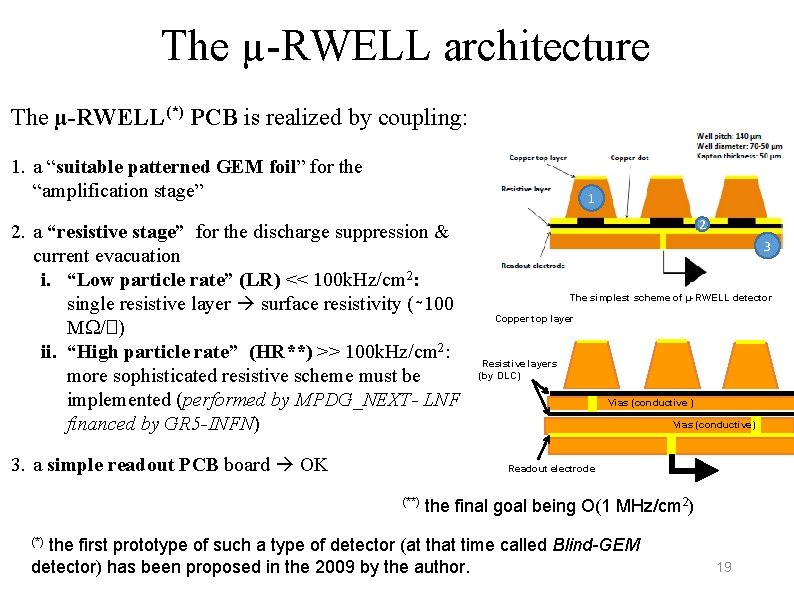
The µ-RWELL architecture The µ-RWELL(*) PCB is realized by coupling: 1. a “suitable patterned GEM foil” for the “amplification stage” 1 2. a “resistive stage” for the discharge suppression & current evacuation i. “Low particle rate” (LR) << 100 k. Hz/cm 2: single resistive layer surface resistivity (∼ 100 M /�) ii. “High particle rate” (HR**) >> 100 k. Hz/cm 2: more sophisticated resistive scheme must be implemented (performed by MPDG_NEXT- LNF financed by GR 5 -INFN) 3. a simple readout PCB board OK 2 3 The simplest scheme of µ-RWELL detector Copper top layer Resistive layers (by DLC) Vias (conductive) Readout electrode (**) the final goal being O(1 MHz/cm 2) the first prototype of such a type of detector (at that time called Blind-GEM detector) has been proposed in the 2009 by the author. (*) 19
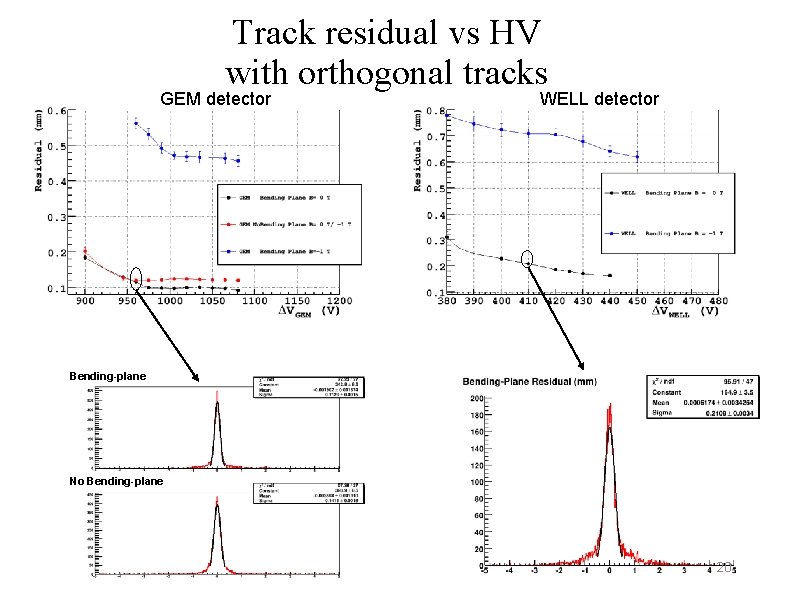
Track residual vs HV with orthogonal tracks GEM detector WELL detector Bending-plane No Bending-plane 20
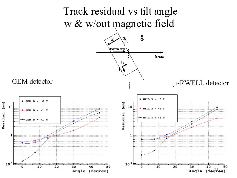
Track residual vs tilt angle w & w/out magnetic field L E B x electron drift beam FE FB GEM detector µ-RWELL detector 21
- Slides: 21