
LABORATORI NAZIONALI DI FRASCATI www lnf infn it
LABORATORI NAZIONALI DI FRASCATI www. lnf. infn. it Gaseous Detectors R&D for the Muon Systems upgrade at LHC G. Bencivenni LNF-INFN 1
Outline q Introduction q ALICE: the Forward Muon Spectrometer q ATLAS: the New Small Wheel (MM & s-TGC) q CMS: the GEM in Y 1/1 q LHCb: the GEM in M 2 q i-RPC for CMS & ATLAS q Conclusions 2
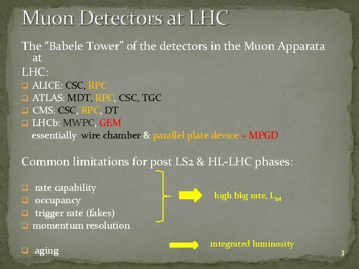
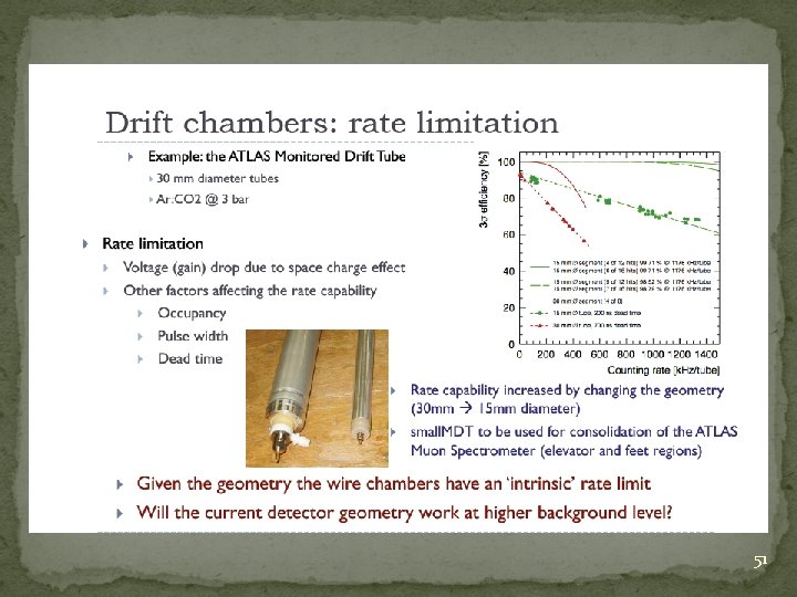
Muon Detectors at LHC The “Babele Tower” of the detectors in the Muon Apparata at LHC: ALICE: CSC, RPC ATLAS: MDT, RPC, CSC, TGC CMS: CSC, RPC, DT LHCb: MWPC, GEM essentially wire chamber & parallel plate device + MPGD q q Common limitations for post LS 2 & HL-LHC phases: q q rate capability occupancy trigger rate (fakes) momentum resolution q aging high bkg rate, List integrated luminosity 3
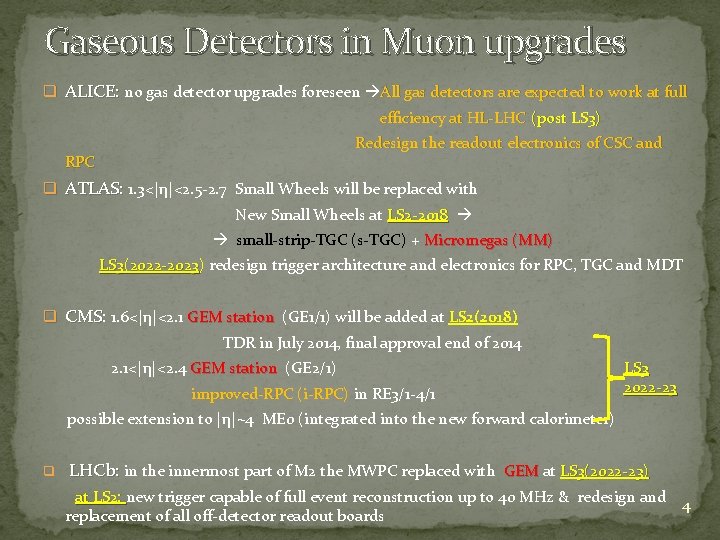
Gaseous Detectors in Muon upgrades q ALICE: no gas detector upgrades foreseen All gas detectors are expected to work at full efficiency at HL-LHC (post LS 3) Redesign the readout electronics of CSC and RPC q ATLAS: 1. 3<|η|<2. 5 -2. 7 Small Wheels will be replaced with New Small Wheels at LS 2 -2018 small-strip-TGC (s-TGC) + Micromegas (MM) LS 3(2022 -2023) redesign trigger architecture and electronics for RPC, TGC and MDT ) q CMS: CMS 1. 6<|η|<2. 1 GEM station (GE 1/1) will be added at LS 2(2018) TDR in July 2014, final approval end of 2014 2. 1<|η|<2. 4 GEM station (GE 2/1) GEM station improved-RPC (i-RPC) in RE 3/1 -4/1 LS 3 2022 -23 possible extension to |η|~4 ME 0 (integrated into the new forward calorimeter) q LHCb: in the innermost part of M 2 the MWPC replaced with GEM at GEM LS 3(2022 -23) at LS 2: new trigger capable of full event reconstruction up to 40 MHz & redesign and at LS 2: 4 replacement of all off-detector readout boards
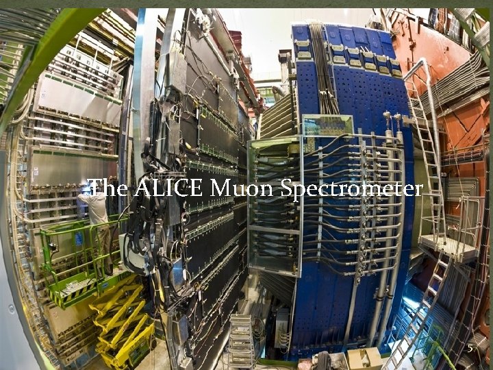
The ALICE Muon Spectrometer 5
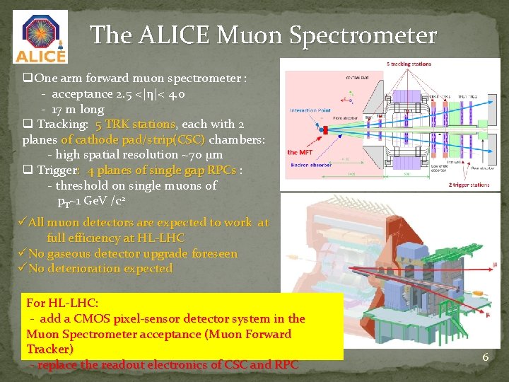
The ALICE Muon Spectrometer q. One arm forward muon spectrometer : - acceptance 2. 5 <|η|< 4. 0 - 17 m long q Tracking: 5 TRK stations, each with 2 5 TRK stations planes of cathode pad/strip(CSC) chambers: of cathode pad/strip(CSC) - high spatial resolution ~70 µm q Trigger: 4 planes of single gap RPCs : : 4 planes of single gap RPCs - threshold on single muons of p. T~1 Ge. V /c 2 üAll muon detectors are expected to work at full efficiency at HL-LHC üNo gaseous detector upgrade foreseen üNo deterioration expected For HL-LHC: - add a CMOS pixel-sensor detector system in the Muon Spectrometer acceptance (Muon Forward Tracker) - replace the readout electronics of CSC and RPC 6
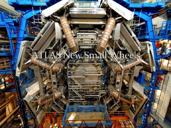
ATLAS New Small Wheels 7
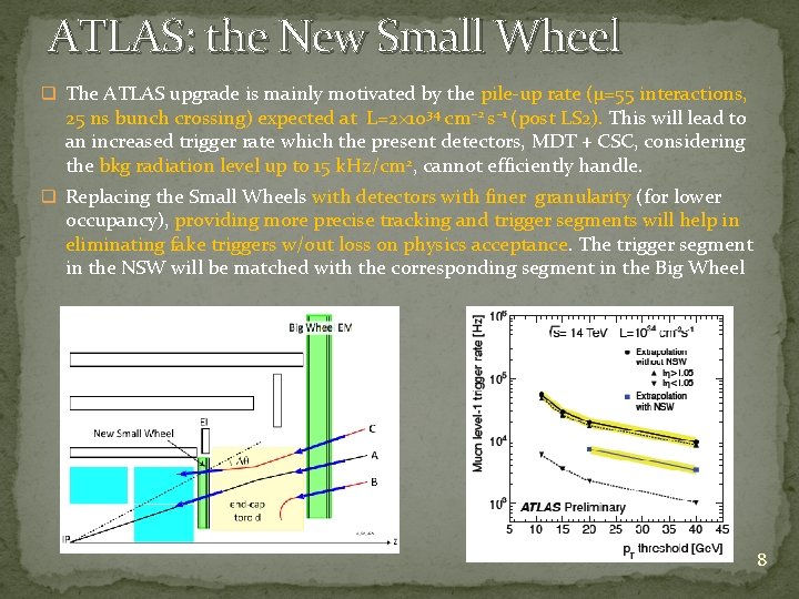
ATLAS: the New Small Wheel q The ATLAS upgrade is mainly motivated by the pile-up rate (μ=55 interactions, 25 ns bunch crossing) expected at L=2× 1034 cm− 2 s− 1 (post LS 2). This will lead to an increased trigger rate which the present detectors, MDT + CSC, considering the bkg radiation level up to 15 k. Hz/cm 2, cannot efficiently handle. q Replacing the Small Wheels with detectors with finer granularity (for lower occupancy), providing more precise tracking and trigger segments will help in eliminating fake triggers w/out loss on physics acceptance. The trigger segment in the NSW will be matched with the corresponding segment in the Big Wheel 8
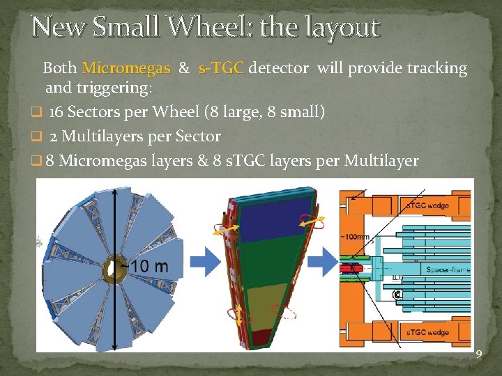
New Small Wheel: the layout Both Micromegas & s-TGC detector will provide tracking Micromegas s-TGC and triggering: q 16 Sectors per Wheel (8 large, 8 small) q 2 Multilayers per Sector q 8 Micromegas layers & 8 s. TGC layers per Multilayer 9
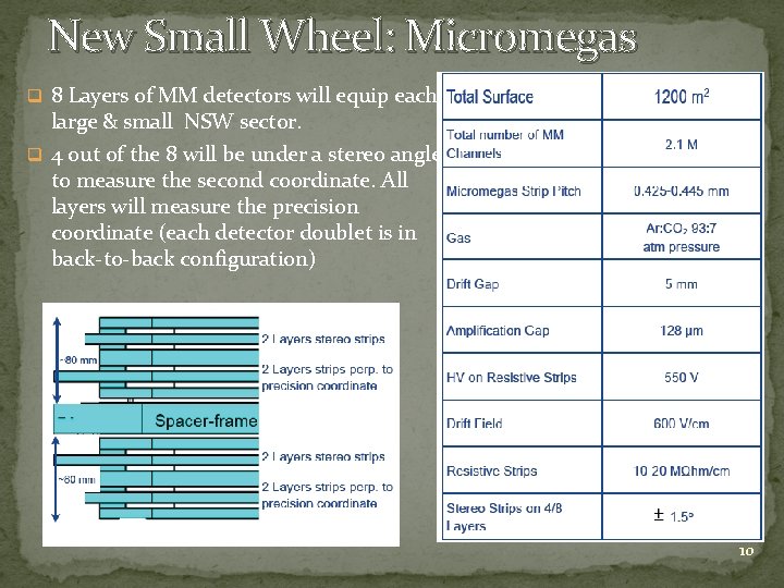
New Small Wheel: Micromegas q 8 Layers of MM detectors will equip each large & small NSW sector. q 4 out of the 8 will be under a stereo angle to measure the second coordinate. All layers will measure the precision coordinate (each detector doublet is in back-to-back configuration) 10
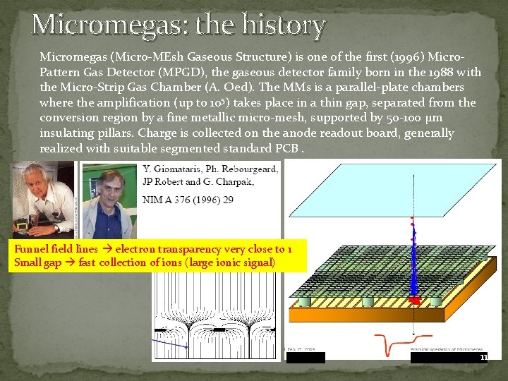
Micromegas: the history Micromegas (Micro-MEsh Gaseous Structure) is one of the first (1996) Micro. Pattern Gas Detector (MPGD), the gaseous detector family born in the 1988 with the Micro-Strip Gas Chamber (A. Oed). The MMs is a parallel-plate chambers where the amplification (up to 105) takes place in a thin gap, separated from the conversion region by a fine metallic micro-mesh, supported by 50 -100 µm insulating pillars. Charge is collected on the anode readout board, generally realized with suitable segmented standard PCB. Funnel field lines electron transparency very close to 1 Small gap fast collection of ions (large ionic signal) 11
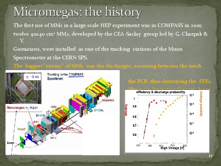
Micromegas: the history The first use of MMs in a large scale HEP experiment was in COMPASS in 2001: twelve 40 x 40 cm 2 MMs, developed by the CEA-Saclay group led by G. Charpak & Y. Giomataris, were installed as one of the tracking stations of the Muon Spectrometer at the CERN SPS. The biggest “enemy” of MMs was the discharges, occurring between the mesh and the PCB, thus destroying the FEEs. The main limitation for very large diffusion of MMs. 12
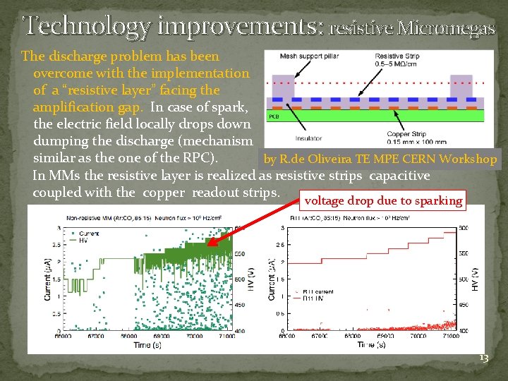
Technology improvements: resistive Micromegas The discharge problem has been overcome with the implementation of a “resistive layer” facing the amplification gap. In case of spark, the electric field locally drops down dumping the discharge (mechanism similar as the one of the RPC). by R. de Oliveira TE MPE CERN Workshop In MMs the resistive layer is realized as resistive strips capacitive coupled with the copper readout strips. voltage drop due to sparking 13
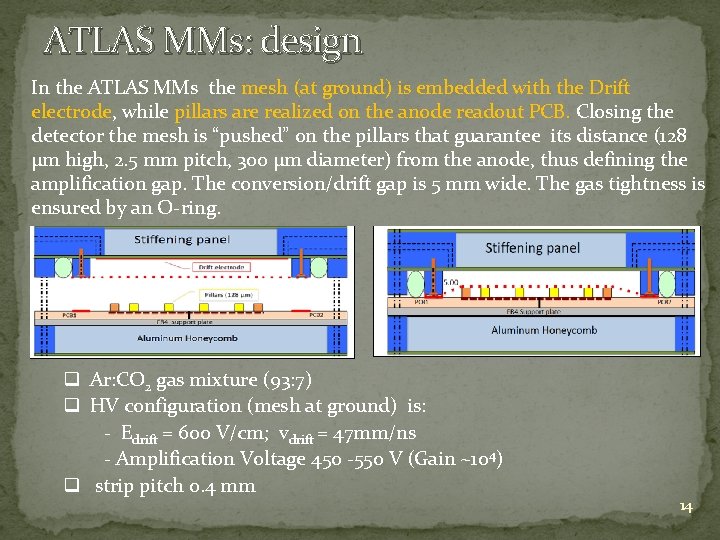
ATLAS MMs: design In the ATLAS MMs the mesh (at ground) is embedded with the Drift electrode, while pillars are realized on the anode readout PCB. Closing the detector the mesh is “pushed” on the pillars that guarantee its distance (128 µm high, 2. 5 mm pitch, 300 µm diameter) from the anode, thus defining the amplification gap. The conversion/drift gap is 5 mm wide. The gas tightness is ensured by an O-ring. q Ar: CO 2 gas mixture (93: 7) q HV configuration (mesh at ground) is: - Edrift = 600 V/cm; vdrift = 47 mm/ns - Amplification Voltage 450 -550 V (Gain ~104) q strip pitch 0. 4 mm 14
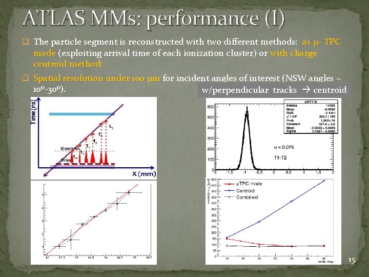
ATLAS MMs: performance (I) q The particle segment is reconstructed with two different methods: as µ- TPC mode (exploiting arrival time of each ionization cluster) or with charge mode centroid method; q Spatial resolution under 100 µm for incident angles of interest (NSW angles ~ Spatial resolution under 100 µm 10 o-30 o). w/perpendicular tracks centroid 15
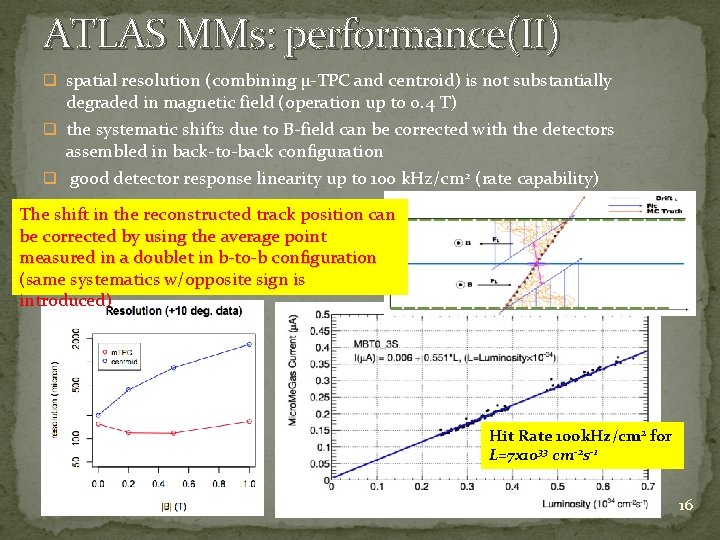
ATLAS MMs: performance(II) q spatial resolution (combining µ-TPC and centroid) is not substantially degraded in magnetic field (operation up to 0. 4 T) q the systematic shifts due to B-field can be corrected with the detectors assembled in back-to-back configuration q good detector response linearity up to 100 k. Hz/cm 2 (rate capability) The shift in the reconstructed track position can be corrected by using the average point measured in a doublet in b-to-b configuration (same systematics w/opposite sign is introduced) Hit Rate 100 k. Hz/cm 2 for L=7 x 1033 cm-2 s-1 16
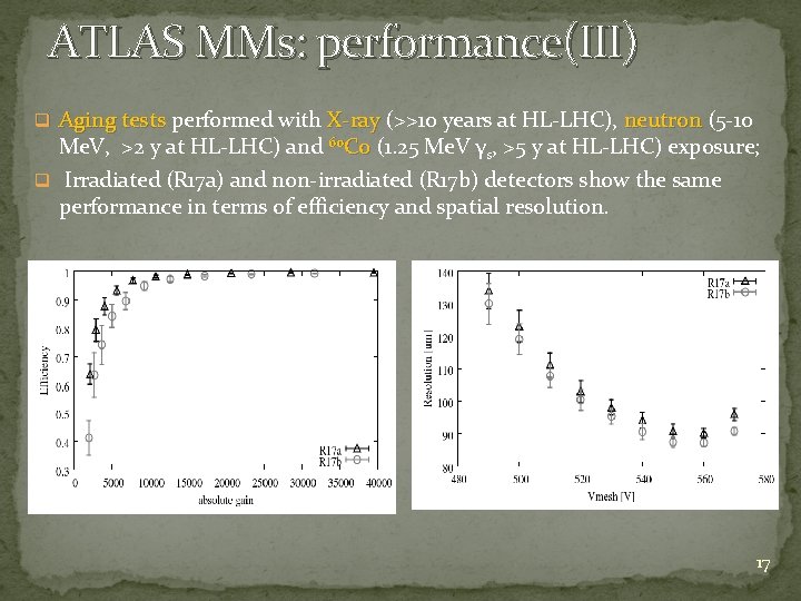
ATLAS MMs: performance(III) q Aging tests performed with X-ray (>>10 years at HL-LHC), neutron (5 -10 Aging tests X-ray neutron Me. V, >2 y at HL-LHC) and 60 Co (1. 25 Me. V γ Co s, >5 y at HL-LHC) exposure; q Irradiated (R 17 a) and non-irradiated (R 17 b) detectors show the same performance in terms of efficiency and spatial resolution. 17
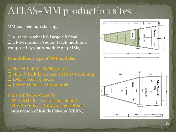
ATLAS–MM production sites MM construction sharing : q 16 sectors/wheel: 8 Large e 8 Small q 2 MM modules/sector (each module is composed by 2 sub-module of 4 MMs) Four different type of MM modules: q SM 1 built by INFN groups q SM 2 built by Germany (LMU + Freiburg) q LM 1 built by Saclay q LM 2 Dubna + Thessaloniki PCBs will be produced by - ELTOS (Italy – LNF responsibility) - ELVIA (France – Saclay responsibility) supervision of Rui de Oliveira (CERN) 18
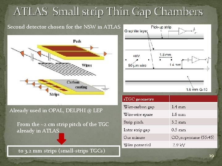
ATLAS Small strip Thin Gap Chambers Second detector chosen for the NSW in ATLAS Already used in OPAL, DELPHI @ LEP From the ~2 cm strip pitch of the TGC already in ATLAS to 3. 2 mm strips (small-strips TGCs) 19
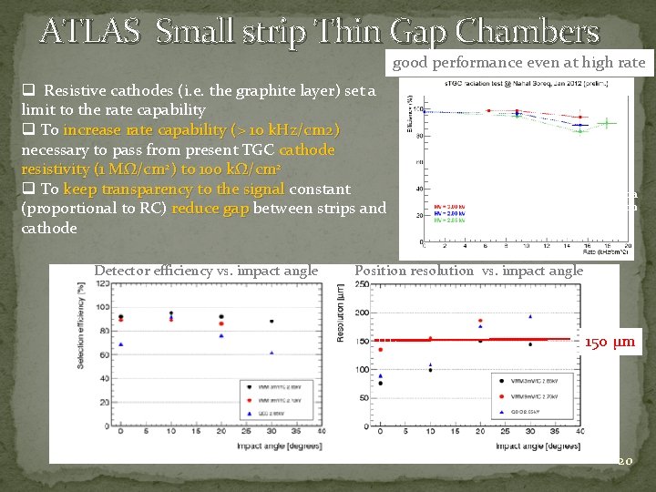
ATLAS Small strip Thin Gap Chambers good performance even at high rate q Resistive cathodes (i. e. the graphite layer) set a limit to the rate capability q To increase rate capability (> 10 k. Hz/cm 2) necessary to pass from present TGC cathode resistivity (1 MΩ/cm 2) to 100 kΩ/cm 2 q To keep transparency to the signal constant keep transparency to the signal (proportional to RC) reduce gap between strips and reduce gap cathode Detector efficiency vs. impact angle Cosmic muon detection under gamma irradiation Position resolution vs. impact angle 150 µm 20
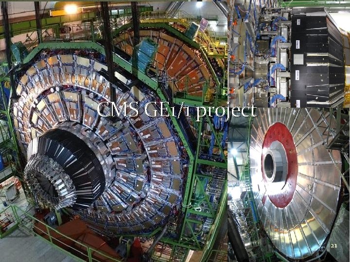
CMS GE 1/1 project 21
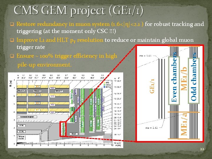
CMS GEM project (GE 1/1) q Restore redundancy in muon system (1. 6<|η|<2. 1 ) for robust tracking and Odd chambers ME 1/b ME 1/a Even chambers GE 1/1 triggering (at the moment only CSC !!!) q Improve L 1 and HLT p. T resolution to reduce or maintain global muon trigger rate q Ensure ~ 100% trigger efficiency in high pile-up environment. 22
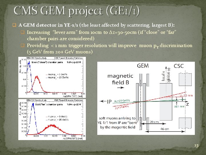
CMS GEM project (GE 1/1) q A GEM detector in YE-1/1 (the least affected by scattering, largest B): q Increasing “lever arm” from 10 cm to Δz=30 -50 cm (if “close” or “far” chamber pairs are considered) q Providing < 1 mm trigger resolution will improve muon p T discrimination (5 Ge. V from 20+ Ge. V muons) 23
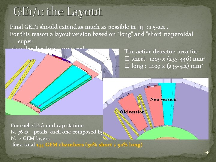
GE 1/1: the Layout Final GE 1/1 should extend as much as possible in |η| : 1. 5 -2. 2. For this reason a layout version based on “long” and “short”trapezoidal super chamber has been proposed. The active detector area for : q short: 1209 x (235 -446) mm 2 q long : 1409 x (235 -512) mm 2 New version Old version For each GE 1/1 end-cap station: N. 36 φ – petals, each one composed by N. 2 GEM layers for a total 144 GEM chambers (50% short + 50% long) 24
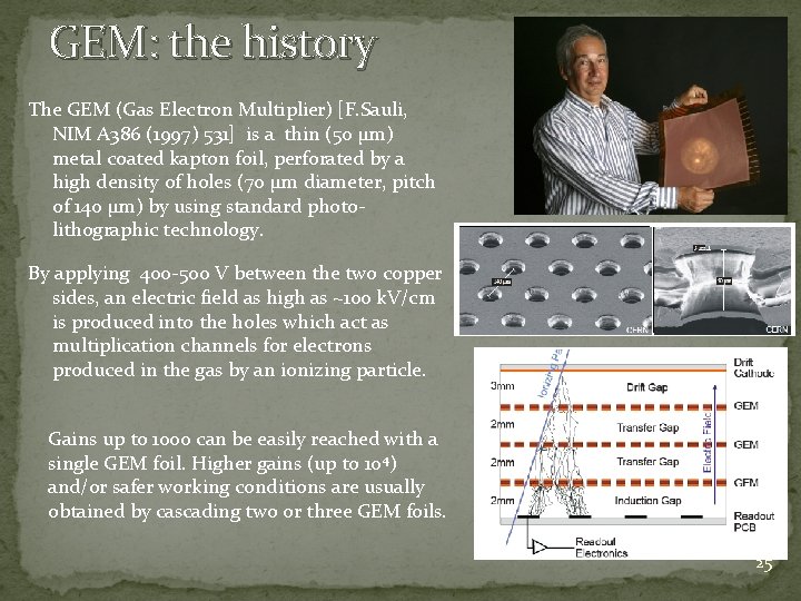
GEM: the history The GEM (Gas Electron Multiplier) [F. Sauli, NIM A 386 (1997) 531] is a thin (50 μm) metal coated kapton foil, perforated by a high density of holes (70 μm diameter, pitch of 140 μm) by using standard photolithographic technology. By applying 400 -500 V between the two copper sides, an electric field as high as ~100 k. V/cm is produced into the holes which act as multiplication channels for electrons produced in the gas by an ionizing particle. Gains up to 1000 can be easily reached with a single GEM foil. Higher gains (up to 104) and/or safer working conditions are usually obtained by cascading two or three GEM foils. 25
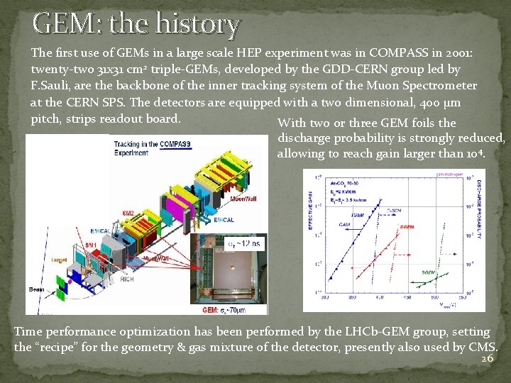
GEM: the history The first use of GEMs in a large scale HEP experiment was in COMPASS in 2001: twenty-two 31 x 31 cm 2 triple-GEMs, developed by the GDD-CERN group led by F. Sauli, are the backbone of the inner tracking system of the Muon Spectrometer at the CERN SPS. The detectors are equipped with a two dimensional, 400 µm pitch, strips readout board. With two or three GEM foils the discharge probability is strongly reduced, allowing to reach gain larger than 104. Time performance optimization has been performed by the LHCb-GEM group, setting the “recipe” for the geometry & gas mixture of the detector, presently also used by CMS. 26
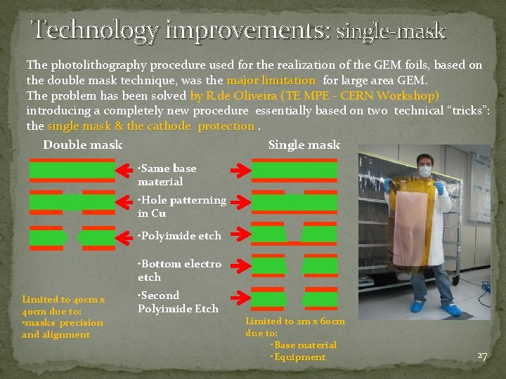
Technology improvements: single-mask The photolithography procedure used for the realization of the GEM foils, based on the double mask technique, was the major limitation for large area GEM. major limitation The problem has been solved by R. de Oliveira (TE MPE - CERN Workshop) introducing a completely new procedure essentially based on two technical “tricks”: the single mask & the cathode protection Double mask Single mask • Same base material • Hole patterning in Cu • Polyimide etch • Bottom electro etch Limited to 40 cm x 40 cm due to: • masks precision and alignment • Second Polyimide Etch Limited to 2 m x 60 cm due to: • Base material • Equipment 27
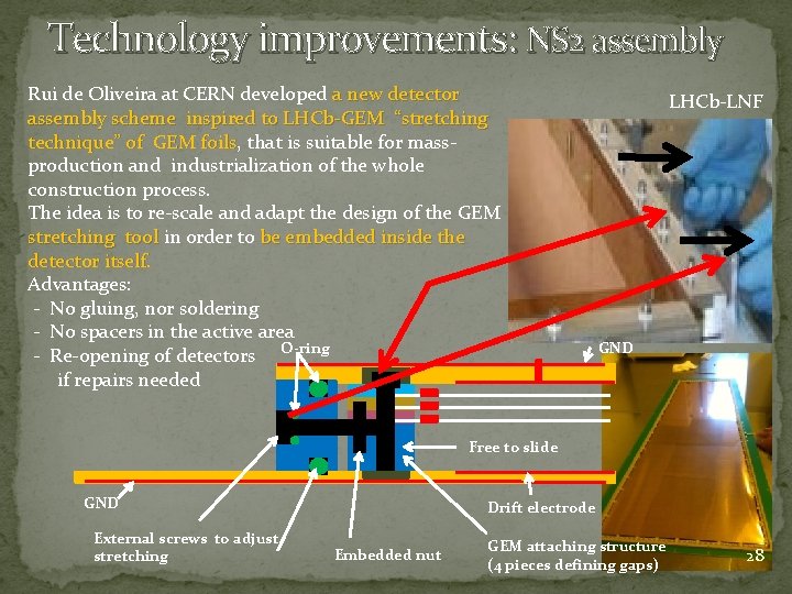
Technology improvements: NS 2 assembly Rui de Oliveira at CERN developed a new detector assembly scheme inspired to LHCb-GEM “stretching technique” of GEM foils, that is suitable for masstechnique” of GEM foils production and industrialization of the whole construction process. The idea is to re-scale and adapt the design of the GEM stretching tool in order to be embedded inside the stretching tool detector itself. Advantages: - No gluing, nor soldering - No spacers in the active area - Re-opening of detectors O-ring if repairs needed LHCb-LNF GND Free to slide GND External screws to adjust stretching Drift electrode Embedded nut GEM attaching structure (4 pieces defining gaps) 28
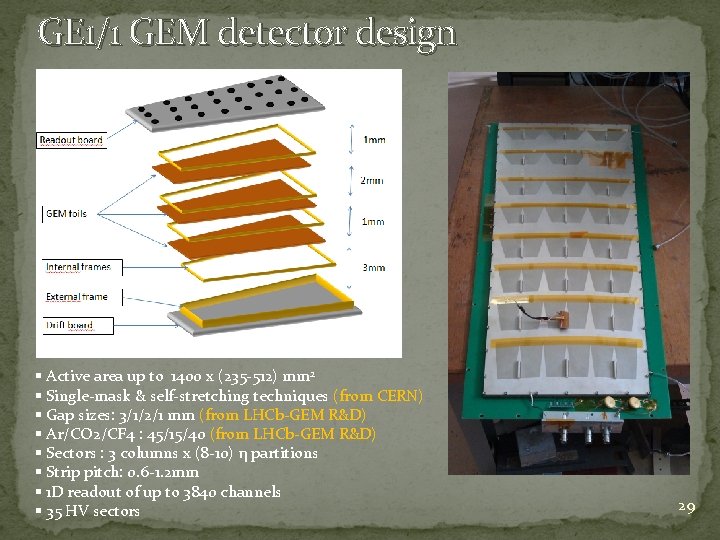
GE 1/1 GEM detector design § Active area up to 1400 x (235 -512) mm 2 § Single-mask & self-stretching techniques (from CERN) § Gap sizes: 3/1/2/1 mm (from LHCb-GEM R&D) § Ar/CO 2/CF 4 : 45/15/40 (from LHCb-GEM R&D) § Sectors : 3 columns x (8 -10) η partitions § Strip pitch: 0. 6 -1. 2 mm § 1 D readout of up to 3840 channels § 35 HV sectors 29
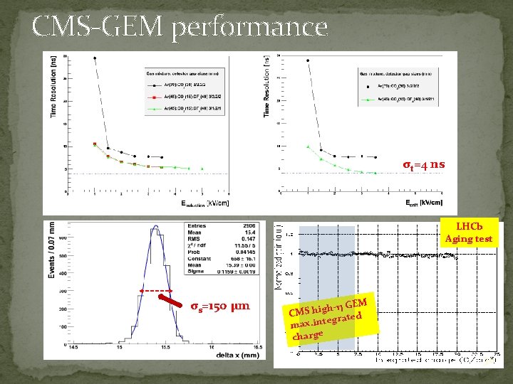
CMS-GEM performance σt=4 ns LHCb Aging test σs=150 µm -η GEM h g i h S CM egrated max. int charge 30
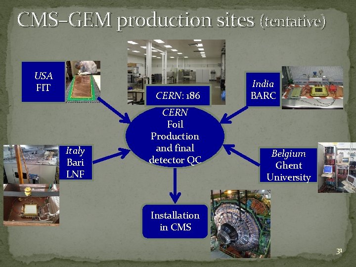
CMS–GEM production sites (tentative) USA FIT CERN: 186 Italy Bari LNF CERN Foil Production and final detector QC India BARC Belgium Ghent University Installation in CMS 31
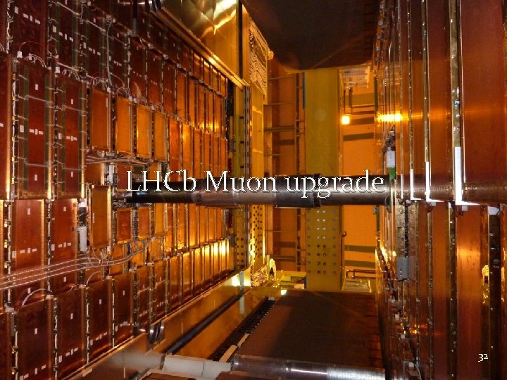
LHCb Muon upgrade 32
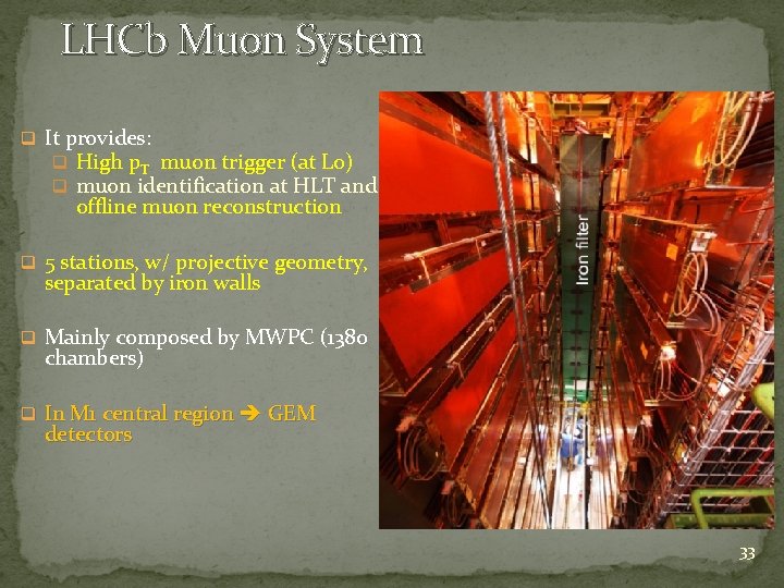
LHCb Muon System q It provides: q High p. T muon trigger (at L 0) q muon identification at HLT and offline muon reconstruction q 5 stations, w/ projective geometry, separated by iron walls q Mainly composed by MWPC (1380 chambers) q In M 1 central region GEM detectors 33
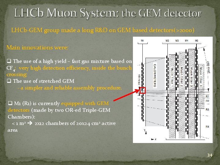
LHCb Muon System: the GEM detector LHCb-GEM group made a long R&D on GEM based detectors(>200 o) Main innovations were: q The use of a high yield – fast gas mixture based on CF 4: very high detection efficiency, inside the bunch crossing; q The use of stretched GEM - a simpler and reliable assembly procedure. q M 1 (R 1) is currently equipped with GEM detectors (made by two OR-ed Triple-GEM detectors Chambers): < 1 m 2 2 x 12 chambers of 20 x 24 cm 2 active area 34
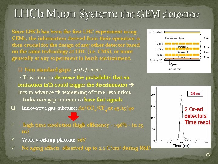
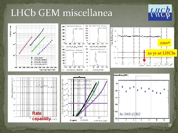
LHCb Muon System: the GEM detector Since LHCb has been the first LHC experiment using GEMs, the information derived from their operation is then crucial for the design of any other detector based on the same technology at LHC (i. e. CMS), or more generally at any experiment in harsh environment. Conversion & q Non-standard gaps: 3/1/2/1 mm : - T 1 is 1 mm to decrease the probability that an ionization in. T 1 could trigger the discriminator hits in advance worsening of time resolution. - Induction gap is 1 1 mm to have fast signals q Innovative gas mixture: Ar/CO 2/CF 4 at 45/15/40 ü ü high time resolution (high efficiency - >96% - in 25 ns) Wide working plateau: 70 V ü No aging effects observed up to 2. 2 C/cm 2 during R&D 2 Or-ed detectors Time resol. 35
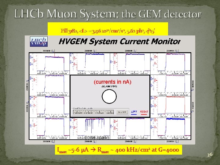
LHCb Muon System: the GEM detector Fill 3182, <L> = 3. 96 1032/cm 2/s-1, 5. 62 pb-1, 4 h 15’ (currents in n. A) Some sparks Imax ~5 -6 µA Rmax ~ 400 k. Hz/cm 2 at G=4000 36
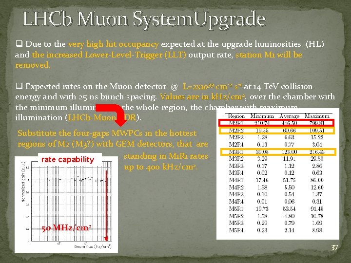
LHCb Muon System. Upgrade q Due to the very high hit occupancy expected at the upgrade luminosities (HL) and the increased Lower-Level-Trigger (LLT) output rate, station M 1 will be removed. q Expected rates on the Muon detector @ L=2 x 1033 cm-2 s-1 at 14 Te. V collision energy and with 25 ns bunch spacing. Values are in k. Hz/cm 2, over the chamber with the minimum illumination, the whole region, the chamber with maximum illumination (LHCb-Muon TDR). Substitute the four-gaps MWPCs in the hottest regions of M 2 (M 3? ) with GEM detectors, that are standing in M 1 R 1 rates rate capability up to 400 k. Hz/cm 2. 50 MHz/cm 2 37
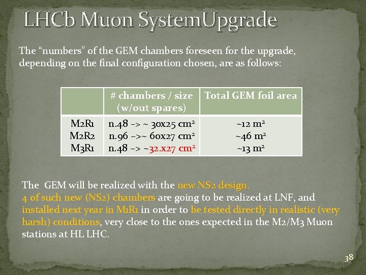
LHCb Muon System. Upgrade The “numbers” of the GEM chambers foreseen for the upgrade, depending on the final configuration chosen, are as follows: M 2 R 1 M 2 R 2 M 3 R 1 # chambers / size (w/out spares) Total GEM foil area n. 48 –> ~ 30 x 25 cm 2 n. 96 –>~ 60 x 27 cm 2 n. 48 –> ~32. x 27 cm 2 ~12 m 2 ~46 m 2 ~13 m 2 The GEM will be realized with the new NS 2 design 4 of such new (NS 2) chambers are going to be realized at LNF, and installed next year in M 1 R 1 in order to be tested directly in realistic (very harsh) conditions, very close to the ones expected in the M 2/M 3 Muon stations at HL LHC. 38
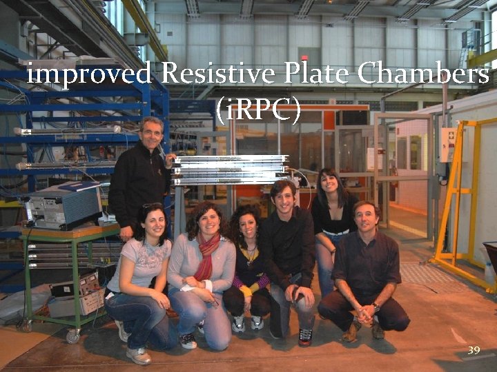
improved Resistive Plate Chambers (i. RPC) 39
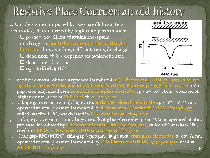
Resistive Plate Counter: an old history q Gas detector composed by two parallel resistive electrodes, characterized by high time performance: q ρ ~ 109− 1012 Ω. cm avalanche/spark discharges a limited area around the avalanche location, thus avoiding self sustaining discharge. location q dead area δ ~ depends on avalanche size q dead time τ ~ ρε q σT ~ Kd/α(E)µ(E)V 1. the first detector of such a type was introduced in (Y. Pestov et al. , NIM 93 ( 1971 ) 269 -27 0) in (Y. Pestov et al. , 1978 by Y. Pestov & G. Fedotovich, 1978 by Y. Pestov & G. Fedotovich Bull. Acad. Sci. USSR, Phys. Ser. 42 (1978) No. 7 122 -123 : thin: 9 10 gap (<100 µm), small area, semiconductive glass electrodes , ρ ~10 -10 Ω. cm , operated at semiconductive glass electrodes high pressure , used at VEPP-2 M σT~20 -30 ps; 10− 1012 Ω. cm , 2. a large gap version (2 mm), large area, melamine-phenolic electrodes, ρ ~10 melamine-phenolic electrodes operated at atm. pressure, introduced by R. Santonico & Cardarelli (NIMA 187(1981)377), called bakelite-RPC , widely used in LHC experiments σT~1 ns; 3. a large gap version (2 mm), large area, float-glass electrodes, ρ ~1012 Ω. cm, operated at atm. pressure, introduced by G. Bencivenni et al (NIMA 300(1991)572), called GSCor Glass-RPC, G. Bencivenni et al (NIMA 300(1991)572), used in OPERA (C. Gustavino NIMA 602(2009)631) σT~1 ns; 12 Ω. cm, 4. Multigap-RPC (MRPC), thin-gap (<300 µm), large area, float-glass electrodes, ρ ~10 , operated at atm. pressure, introduced by C. Williams et al (NIMA 374(1996)132), used in , ALICE-TOF σT<50 ps; 40
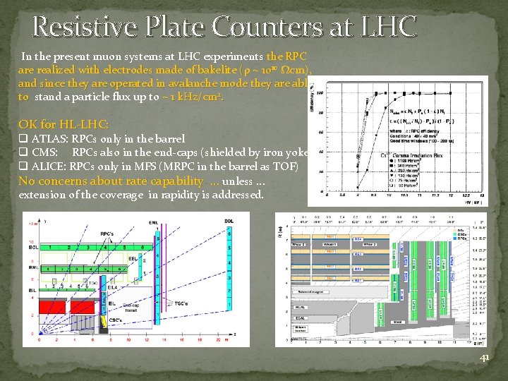
Resistive Plate Counters at LHC In the present muon systems at LHC experiments the RPC are realized with electrodes made of bakelite (ρ ~ 1010 Ωcm), and since they are operated in avalanche mode they are able to stand a particle flux up to ~ 1 k. Hz/cm 2. to OK for HL-LHC: q ATLAS: RPCs only in the barrel q CMS: RPCs also in the end-caps (shielded by iron yoke) q ALICE: RPCs only in MFS (MRPC in the barrel as TOF) No concerns about rate capability … unless … extension of the coverage in rapidity is addressed. 41
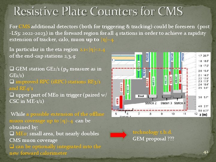
Resistive Plate Counters for CMS For CMS additional detectors (both for triggering & tracking) could be foreseen (post CMS -LS 3: 2022 -2023) in the forward region for all 4 stations in order to achieve a rapidity extension of tracker, calo, muon up to |η|~4. In particular in the eta region 2. 1<|η|<2. 4 of the end-cap stations 2, 3, 4: q GEM station GE 2/1 (p. T measure as in GE 1/1) q improved RPC (i. RPC) stations RE 3/1 and RE 4/1 q upper part of ME 0 in trigger (paired w/ CSC in ME-1/1) While a possible extension of the offline muon coverage up to |η|~4 can be obtained by: q ME 0: small area, but nearly doubles ME 0 CMS muon coverage q can be optionally integrated into the new forward calorimeter technology t. b. d. GEM proposal ? ? ? 42
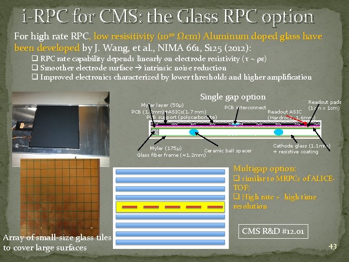
i-RPC for CMS: the Glass RPC option For high rate RPC, low resisitivity (1010 Ωcm) Aluminum doped glass have been developed by J. Wang, et al. , NIMA 661, S 125 (2012): been developed q RPC rate capability depends linearly on electrode resistivity (τ ~ ρε) q Smoother electrode surface intrinsic noise reduction q Improved electronics characterized by lower thresholds and higher amplification Single gap option Mylar layer (50μ) PCB (1. 2 mm)+ASICs(1. 7 mm) PCB support (polycarbonate) PCB interconnect Readout pads (1 cm x 1 cm) Readout ASIC (Hardroc 2, 1. 6 mm) Gas gap(1. 2 mm) Mylar (175μ) Ceramic ball spacer Glass fiber frame (≈1. 2 mm) Cathode glass (1. 1 mm) + resistive coating Multigap option: q similar to MRPCs of ALICETOF; q High rate + high time resolution Array of small-size glass tiles to cover large surfaces CMS R&D #12. 01 43
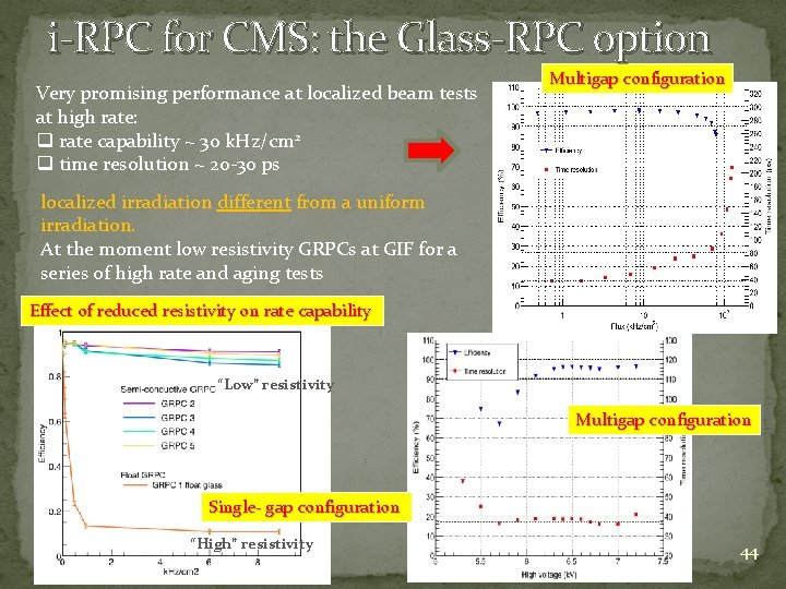
i-RPC for CMS: the Glass-RPC option Very promising performance at localized beam tests at high rate: q rate capability ~ 30 k. Hz/cm 2 q time resolution ~ 20 -30 ps Multigap configuration localized irradiation different from a uniform irradiation. At the moment low resistivity GRPCs at GIF for a series of high rate and aging tests Effect of reduced resistivity on rate capability “Low” resistivity Multigap configuration Single- gap configuration “High” resistivity 44
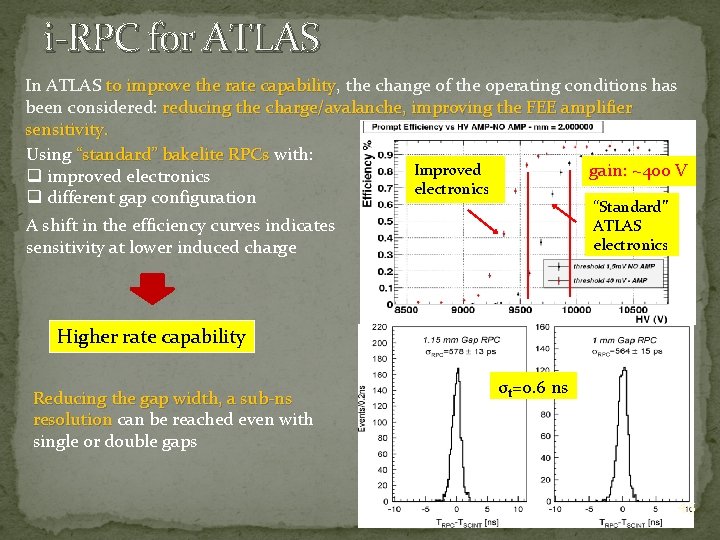
i-RPC for ATLAS In ATLAS to improve the rate capability, the change of the operating conditions has to improve the rate capability been considered: reducing the charge/avalanche, improving the FEE amplifier sensitivity. Using “standard” bakelite RPCs with: “standard” bakelite RPCs Improved gain: ~400 V q improved electronics q different gap configuration “Standard” A shift in the efficiency curves indicates sensitivity at lower induced charge ATLAS electronics Higher rate capability Reducing the gap width, a sub-ns resolution can be reached even with resolution single or double gaps σt=0. 6 ns 45
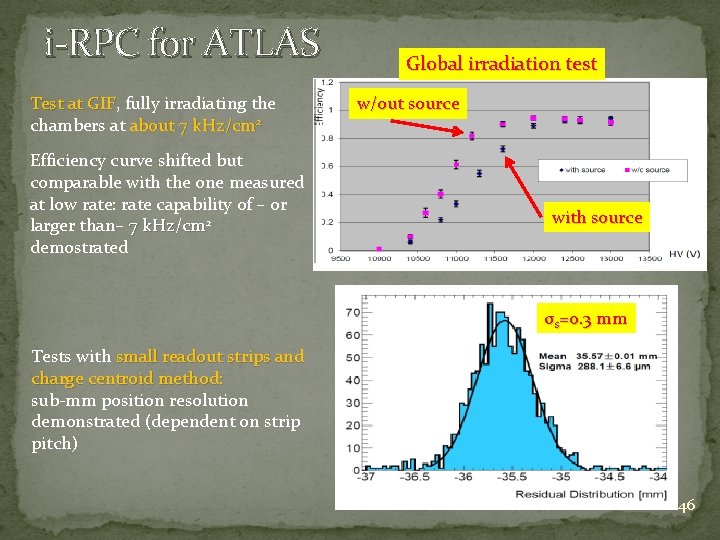
i-RPC for ATLAS Test at GIF, fully irradiating the Test at GIF chambers at about 7 k. Hz/cm 2 Efficiency curve shifted but comparable with the one measured at low rate: rate capability of – or larger than– 7 k. Hz/cm 2 demostrated Global irradiation test w/out source with source σs=0. 3 mm Tests with small readout strips and charge centroid method: sub-mm position resolution demonstrated (dependent on strip pitch) 46
Conclusions q Gaseous detectors are still today the only way to equip Gaseous detectors large volumes at a reasonable cost, with good space and time resolution and limited material budget q MPGDs thanks to their large potentiality especially in MPGDs terms of rate capability and the impressive technological rate capability progress made during the last years ( RD 51), are gaining progress RD 51 an enormous space in the HEP environment (not only as muon devices…) q RPCs , “still … in the spotlight … after all these years “, are RPCs , subject of lot of interesting and fruitful R&Ds 47

Aknowledgements I would like to thank many colleagues for the help in I would like to thank many colleagues collecting the information needed for this presentation: M. Abbrescia, A. Cardini, A. di Ciaccio, G. Fedotovich , P. Iengo, M. Iodice, Y. Pestov and D. Piccolo THANKS for the attention 48
Spare slides 49
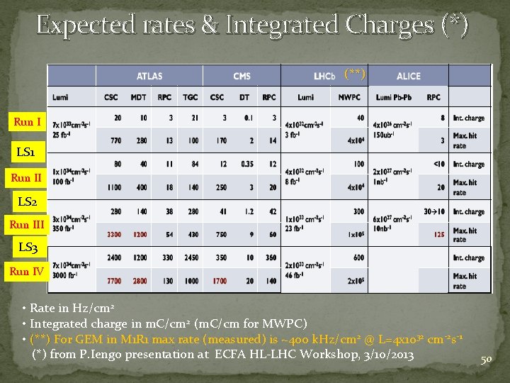
Expected rates & Integrated Charges (*) (**) Run I LS 1 Run II LS 2 Run III LS 3 Run IV • Rate in Hz/cm 2 • Integrated charge in m. C/cm 2 (m. C/cm for MWPC) 2 @ L=4 x 1032 cm-2 s-1 • (**) For GEM in M 1 R 1 max rate (measured) is ~400 k. Hz/cm (**) (*) from P. Iengo presentation at ECFA HL-LHC Workshop, 3/10/2013 50
51
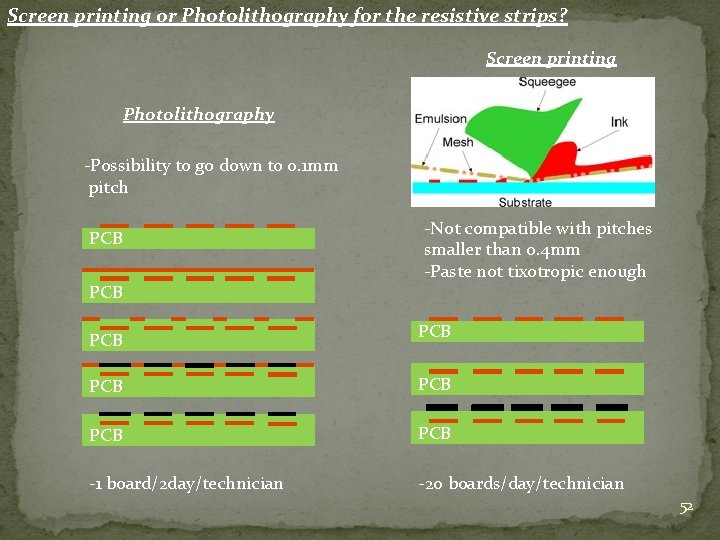
Screen printing or Photolithography for the resistive strips? Screen printing Photolithography -Possibility to go down to 0. 1 mm pitch PCB -Not compatible with pitches smaller than 0. 4 mm -Paste not tixotropic enough PCB PCB PCB -1 board/2 day/technician -20 boards/day/technician 52
LHCb GEM miscellanea 2 x 10⁴ 10 ys at LHCb 1 Rate capability G~4000 G~17000 53
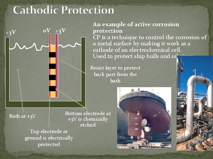
Cathodic Protection 0 V +3 V An example of active corrosion protection CP is a technique to control the corrosion of a metal surface by making it work as a cathode of an electrochemical cell. Used to protect ship hulls and oil pipes Resist layer to protect back part from the bath Bottom electrode at +3 V is chemically etched Top electrode at ground is electrically protected Bath at +3 V 54
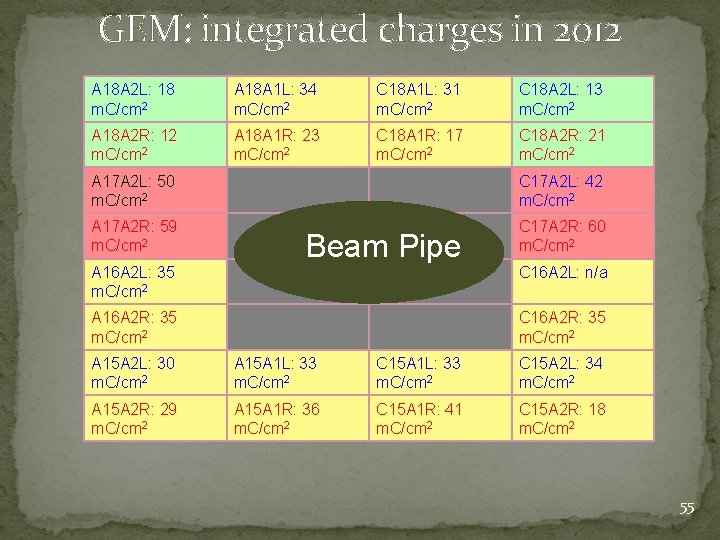
GEM: integrated charges in 2012 A 18 A 2 L: 18 m. C/cm 2 A 18 A 1 L: 34 m. C/cm 2 C 18 A 1 L: 31 m. C/cm 2 C 18 A 2 L: 13 m. C/cm 2 A 18 A 2 R: 12 m. C/cm 2 A 18 A 1 R: 23 m. C/cm 2 C 18 A 1 R: 17 m. C/cm 2 C 18 A 2 R: 21 m. C/cm 2 A 17 A 2 L: 50 m. C/cm 2 C 17 A 2 L: 42 m. C/cm 2 A 17 A 2 R: 59 m. C/cm 2 C 17 A 2 R: 60 m. C/cm 2 A 16 A 2 L: 35 m. C/cm 2 Beam Pipe A 16 A 2 R: 35 m. C/cm 2 C 16 A 2 L: n/a C 16 A 2 R: 35 m. C/cm 2 A 15 A 2 L: 30 m. C/cm 2 A 15 A 1 L: 33 m. C/cm 2 C 15 A 2 L: 34 m. C/cm 2 A 15 A 2 R: 29 m. C/cm 2 A 15 A 1 R: 36 m. C/cm 2 C 15 A 1 R: 41 m. C/cm 2 C 15 A 2 R: 18 m. C/cm 2 55
56
- Slides: 56