
Lab 7 Introduction to Arduino ENGG 1100 Engineering
Lab 7: Introduction to Arduino ENGG 1100 Engineering Design I l Study this document before coming to the lab l Demonstrate your results of the following exercises to a TA before the lab ends. l l Part (b) of Exercise 7. 1 (page 28) Part (b) of Exercise 7. 2 (page 33) Exercise 7. 3 (page 41) Exercise 7. 4 d (page 52) This material is based on various resources
Introd. | Arduino | basic func. | exp 71 -LED | exp 72 -Input | exp 73 -PWM | exp 74 -FSM Overview • Theory • Introduction to Arduino • Hardware system structure • Programming structure • Practice • • Experiment 1: LED control Experiment 1: Input/output functions Experiment 2: Pulse width modulation (PWM) Experiment 3: Finite State machines (FSM) 10/3/2014 2
Introd. | Arduino | basic func. | exp 71 -LED | exp 72 -Input | exp 73 -PWM | exp 74 -FSM Introduction to Arduino • Arduino is a computation tool for sensing and controlling signals • It is more convenient and cost effective than using a personal computer PC. • It's an open-source system in terms of hardware and software. • You can download the Integrated Development Environment (IDE) for your own OS from http: //arduino. cc/en/Main/Software • Follow the instruction to install the IDE 10/3/2014 3

Introd. | Arduino | basic func. | exp 71 -LED | exp 72 -Input | exp 73 -PWM | exp 74 -FSM Arduino UNO • Microcontroller is based on ATmega 328 14 digital input/output (I/O) pins 13, 12, … ……… 2, 1, 0 • If needed , download Arduino Integrated Development Environment IDE http: //arduino. cc/en/Main/Software#toc 1 • 14 digital input/output (I/O) pins plus • 6 analog input pins (these pins can also be programmed to be digital I/O pins) • A 16 MHz ceramic resonator 10/3/2014 A 0 - A 5 6 Analog inputs, they can also be used as digital I/O pins 4
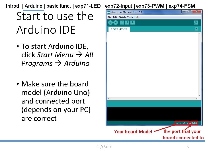
Introd. | Arduino | basic func. | exp 71 -LED | exp 72 -Input | exp 73 -PWM | exp 74 -FSM Start to use the Arduino IDE • To start Arduino IDE, click Start Menu All Programs Arduino • Make sure the board model (Arduino Uno) and connected port (depends on your PC) are correct Your board Model 10/3/2014 The port that your board connected to 5
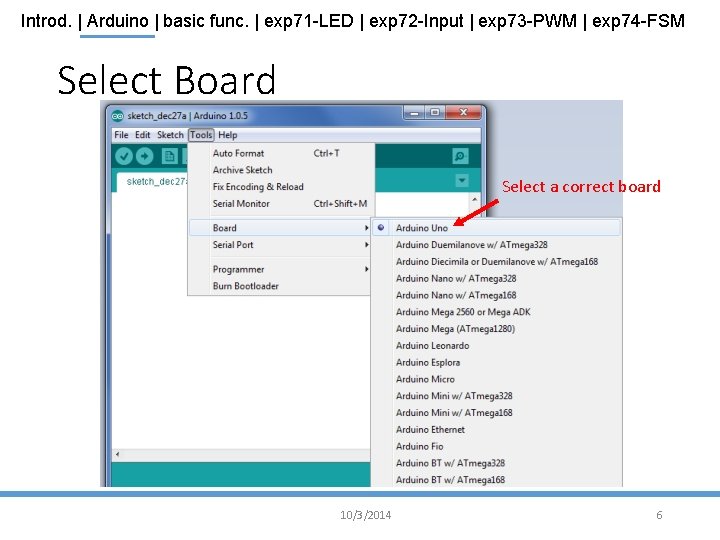
Introd. | Arduino | basic func. | exp 71 -LED | exp 72 -Input | exp 73 -PWM | exp 74 -FSM Select Board Select a correct board 10/3/2014 6
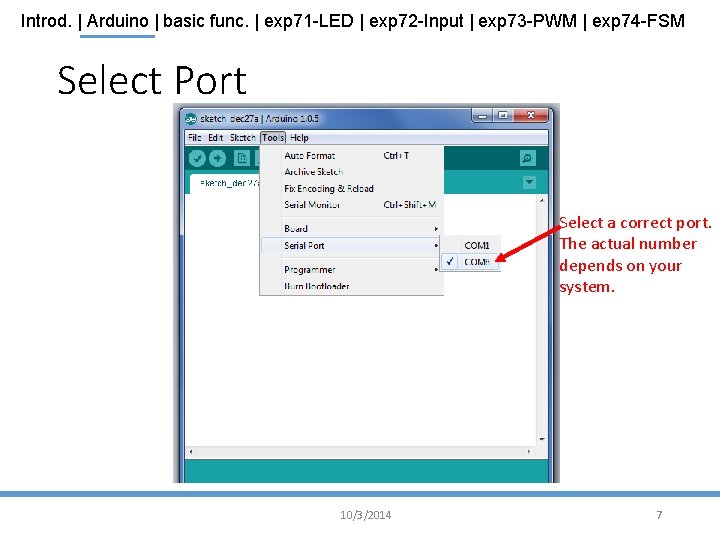
Introd. | Arduino | basic func. | exp 71 -LED | exp 72 -Input | exp 73 -PWM | exp 74 -FSM Select Port Select a correct port. The actual number depends on your system. 10/3/2014 7

Introd. | Arduino | basic func. | exp 71 -LED | exp 72 -Input | exp 73 -PWM | exp 74 -FSM Arduino IDE Tool Bar This programming Area is called “Sketch”. Serial monitor, Can use this to issue commands to the board, and read outputs from the board. The program code are placed here. Status Messages from the system 10/3/2014 8
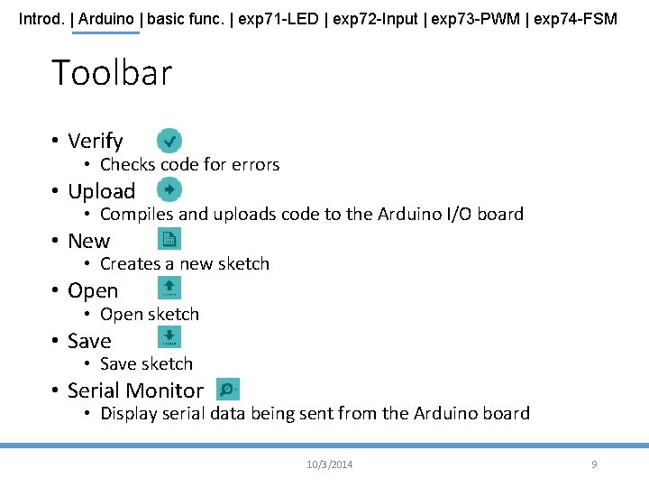
Introd. | Arduino | basic func. | exp 71 -LED | exp 72 -Input | exp 73 -PWM | exp 74 -FSM Toolbar • Verify • Checks code for errors • Upload • Compiles and uploads code to the Arduino I/O board • New • Creates a new sketch • Open sketch • Save sketch • Serial Monitor • Display serial data being sent from the Arduino board 10/3/2014 9
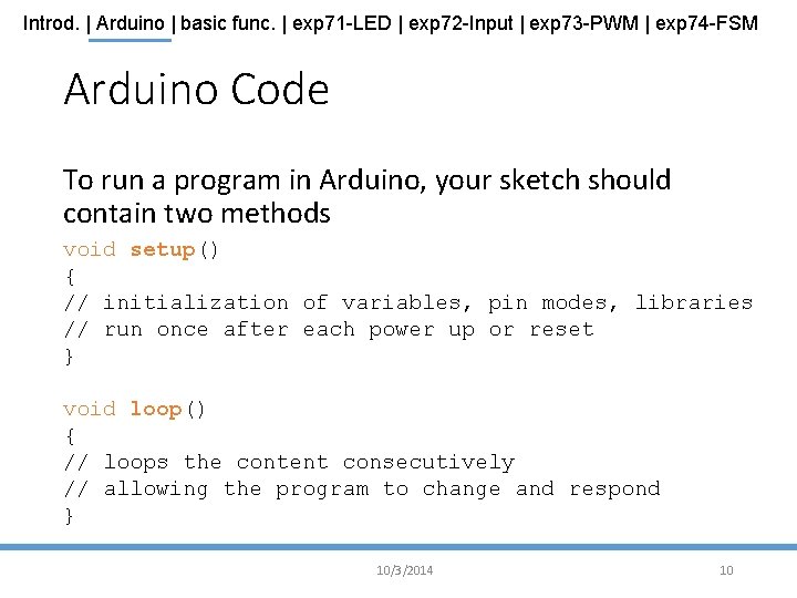
Introd. | Arduino | basic func. | exp 71 -LED | exp 72 -Input | exp 73 -PWM | exp 74 -FSM Arduino Code To run a program in Arduino, your sketch should contain two methods void setup() { // initialization of variables, pin modes, libraries // run once after each power up or reset } void loop() { // loops the content consecutively // allowing the program to change and respond } 10/3/2014 10
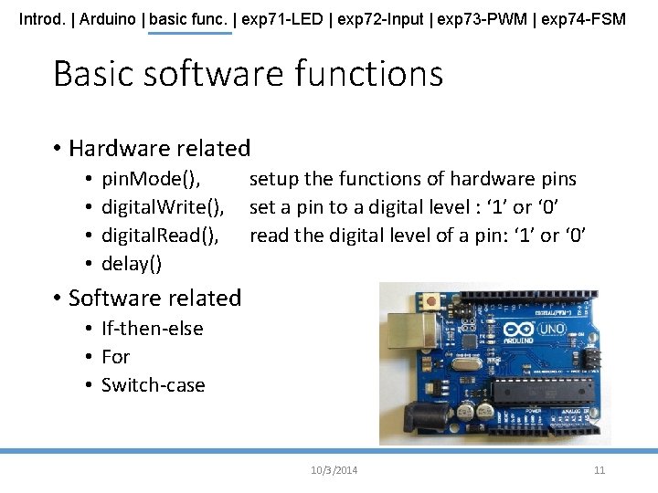
Introd. | Arduino | basic func. | exp 71 -LED | exp 72 -Input | exp 73 -PWM | exp 74 -FSM Basic software functions • Hardware related • • pin. Mode(), digital. Write(), digital. Read(), delay() setup the functions of hardware pins set a pin to a digital level : ‘ 1’ or ‘ 0’ read the digital level of a pin: ‘ 1’ or ‘ 0’ • Software related • If-then-else • For • Switch-case 10/3/2014 11
Introd. | Arduino | basic func. | exp 71 -LED | exp 72 -Input | exp 73 -PWM | exp 74 -FSM System setup procedures • (Step 1) Setup the direction of the pins: • using pin. Mode(), • (Step 2) Then you can set a pin to : HIGH or LOW • (Step 2 a) digital. Write(), //set pin to : HIGH ‘ 1’ or LOW ‘ 0’ • or • (step 2 b) digital. Read(), //read state of pin: HIGH ‘ 1’ or LOW ‘ 0’ 10/3/2014 12
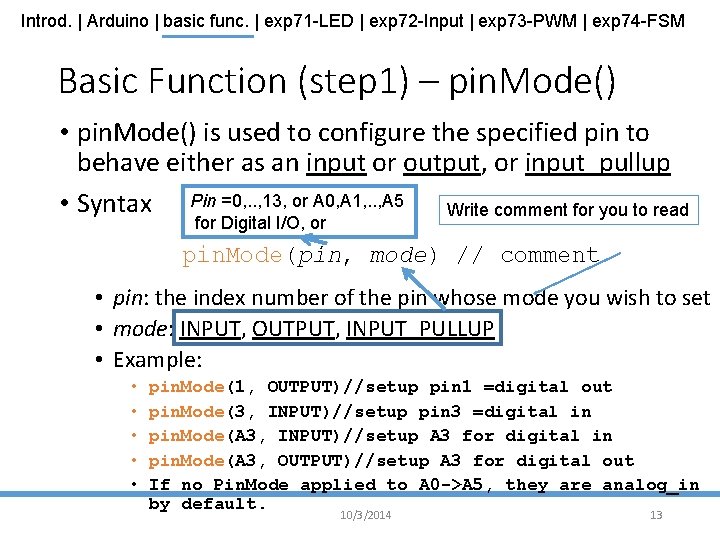
Introd. | Arduino | basic func. | exp 71 -LED | exp 72 -Input | exp 73 -PWM | exp 74 -FSM Basic Function (step 1) – pin. Mode() • pin. Mode() is used to configure the specified pin to behave either as an input or output, or input_pullup • Syntax Pin =0, . . , 13, or A 0, A 1, . . , A 5 Write comment for you to read for Digital I/O, or pin. Mode(pin, mode) // comment • pin: the index number of the pin whose mode you wish to set • mode: INPUT, OUTPUT, INPUT_PULLUP • Example: • • • pin. Mode(1, OUTPUT)//setup pin 1 =digital out pin. Mode(3, INPUT)//setup pin 3 =digital in pin. Mode(A 3, INPUT)//setup A 3 for digital in pin. Mode(A 3, OUTPUT)//setup A 3 for digital out If no Pin. Mode applied to A 0 ->A 5, they are analog_in by default. 10/3/2014 13
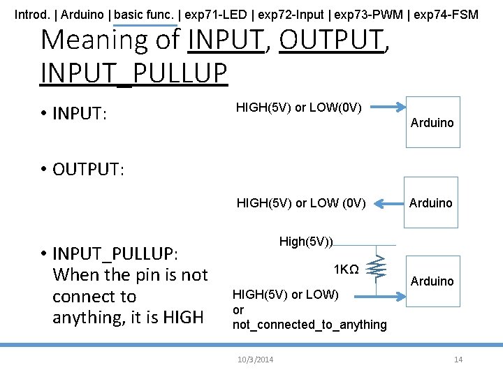
Introd. | Arduino | basic func. | exp 71 -LED | exp 72 -Input | exp 73 -PWM | exp 74 -FSM Meaning of INPUT, OUTPUT, INPUT_PULLUP • INPUT: HIGH(5 V) or LOW(0 V) Arduino • OUTPUT: HIGH(5 V) or LOW (0 V) • INPUT_PULLUP: When the pin is not connect to anything, it is HIGH Arduino High(5 V)) 1 KΩ HIGH(5 V) or LOW) or not_connected_to_anything 10/3/2014 Arduino 14
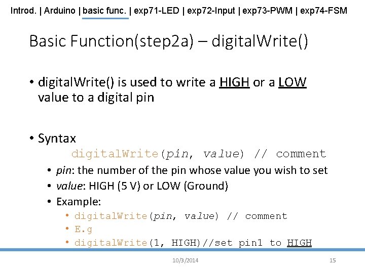
Introd. | Arduino | basic func. | exp 71 -LED | exp 72 -Input | exp 73 -PWM | exp 74 -FSM Basic Function(step 2 a) – digital. Write() • digital. Write() is used to write a HIGH or a LOW value to a digital pin • Syntax digital. Write(pin, value) // comment • pin: the number of the pin whose value you wish to set • value: HIGH (5 V) or LOW (Ground) • Example: • digital. Write(pin, value) // comment • E. g • digital. Write(1, HIGH)//set pin 1 to HIGH 10/3/2014 15
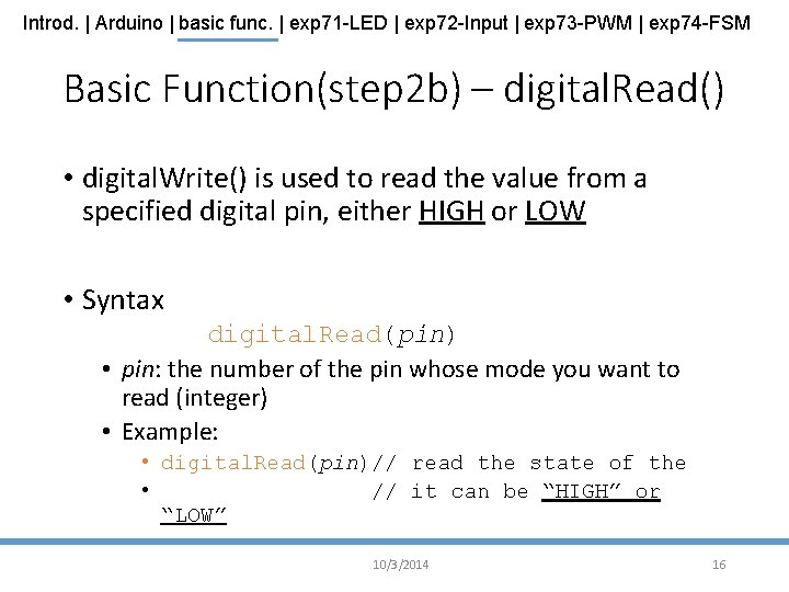
Introd. | Arduino | basic func. | exp 71 -LED | exp 72 -Input | exp 73 -PWM | exp 74 -FSM Basic Function(step 2 b) – digital. Read() • digital. Write() is used to read the value from a specified digital pin, either HIGH or LOW • Syntax digital. Read(pin) • pin: the number of the pin whose mode you want to read (integer) • Example: • digital. Read(pin)// read the state of the • // it can be “HIGH” or “LOW” 10/3/2014 16
Introd. | Arduino | basic func. | exp 71 -LED | exp 72 -Input | exp 73 -PWM | exp 74 -FSM Some other basic Function – delay() • delay() is used to pause the program for the amount of time (in milliseconds) • Syntax delay(ms) • ms: the number of milliseconds to pause (unsigned long) 10/3/2014 17

Introd. | Arduino | basic func. | exp 71 -LED | exp 72 -Input | exp 73 -PWM | exp 74 -FSM Basic Control Structure – IF • Syntax IF(condition 1){ // do stuff if condition 1 is true }ELSE IF (condition 2){ // do stuff only if condition 1 is false // and conition 2 is true }ELSE{ // do stuff when both condition 1 and // condition 2 are false } 10/3/2014 18
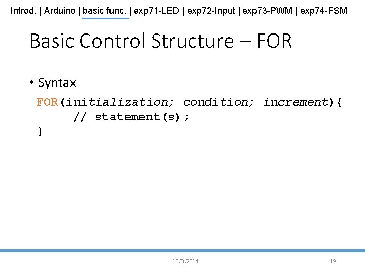
Introd. | Arduino | basic func. | exp 71 -LED | exp 72 -Input | exp 73 -PWM | exp 74 -FSM Basic Control Structure – FOR • Syntax FOR(initialization; condition; increment){ // statement(s); } 10/3/2014 19
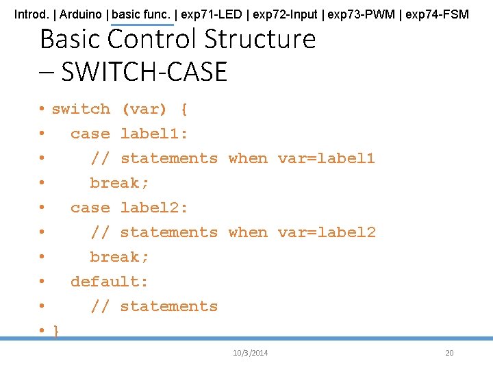
Introd. | Arduino | basic func. | exp 71 -LED | exp 72 -Input | exp 73 -PWM | exp 74 -FSM Basic Control Structure – SWITCH-CASE • switch (var) { • case label 1: • // statements when var=label 1 • break; • case label 2: • // statements when var=label 2 • break; • default: • // statements • } 10/3/2014 20
Introd. | Arduino | basic func. | exp 71 -LED | exp 72 -Input | exp 73 -PWM | exp 74 -FSM More Functions • Please visit http: //arduino. cc/en/Reference/ for Arduino Language Reference 10/3/2014 21
Introd. | Arduino | basic func. | exp 71 -LED | exp 72 -Input | exp 73 -PWM | exp 74 -FSM Experiment 7. 1: Blinks an LED Turns on/off an Active-LOW LED 10/3/2014 22
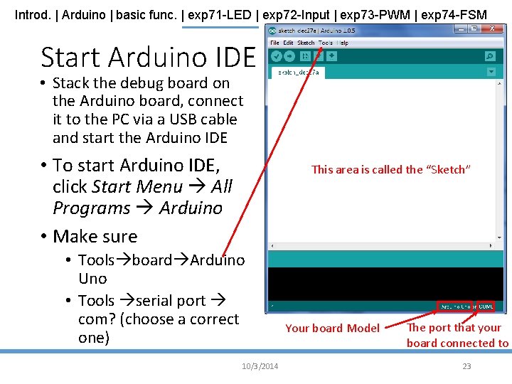
Introd. | Arduino | basic func. | exp 71 -LED | exp 72 -Input | exp 73 -PWM | exp 74 -FSM Start Arduino IDE • Stack the debug board on the Arduino board, connect it to the PC via a USB cable and start the Arduino IDE • To start Arduino IDE, click Start Menu All Programs Arduino • Make sure This area is called the “Sketch” • Tools board Arduino Uno • Tools serial port com? (choose a correct one) 10/3/2014 Your board Model The port that your board connected to 23
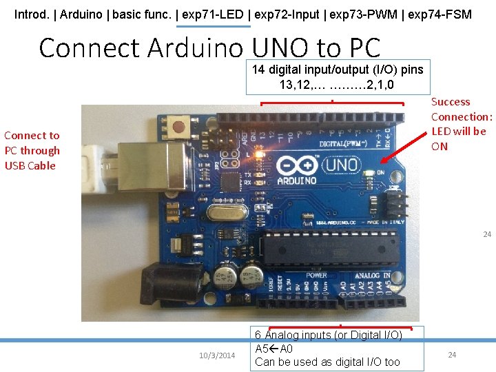
Introd. | Arduino | basic func. | exp 71 -LED | exp 72 -Input | exp 73 -PWM | exp 74 -FSM Connect Arduino UNO to PC 14 digital input/output (I/O) pins 13, 12, … ……… 2, 1, 0 Success Connection: LED will be ON Connect to PC through USB Cable 24 10/3/2014 6 Analog inputs (or Digital I/O) A 5 A 0 Can be used as digital I/O too 24
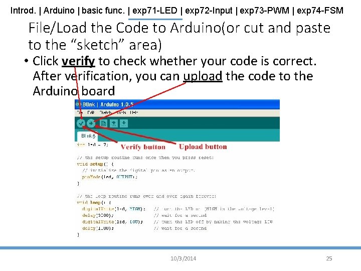
Introd. | Arduino | basic func. | exp 71 -LED | exp 72 -Input | exp 73 -PWM | exp 74 -FSM File/Load the Code to Arduino(or cut and paste to the “sketch” area) • Click verify to check whether your code is correct. After verification, you can upload the code to the Arduino board 10/3/2014 25
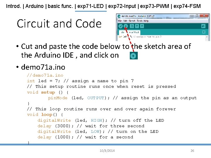
Introd. | Arduino | basic func. | exp 71 -LED | exp 72 -Input | exp 73 -PWM | exp 74 -FSM Circuit and Code • Cut and paste the code below to the sketch area of the Arduino IDE , and click on • demo 71 a. ino //demo 71 a. ino int led = 7; // assign a name to pin 7 // This setup routine runs once when reset is pressed void setup () { pin. Mode (led, OUTPUT); // assign the pin as an output } // This loop routine runs over and over again forever void loop() { digital. Write (led, HIGH); // turn off the LED delay (3000); // wait for three second digital. Write (led, LOW); // turn on the LED delay (1000); // wait for a second } 10/3/2014 26
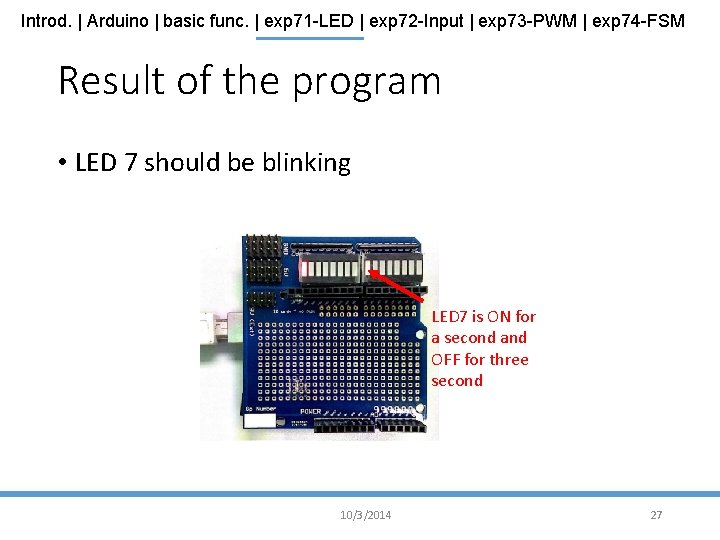
Introd. | Arduino | basic func. | exp 71 -LED | exp 72 -Input | exp 73 -PWM | exp 74 -FSM Result of the program • LED 7 should be blinking LED 7 is ON for a second and OFF for three second 10/3/2014 27
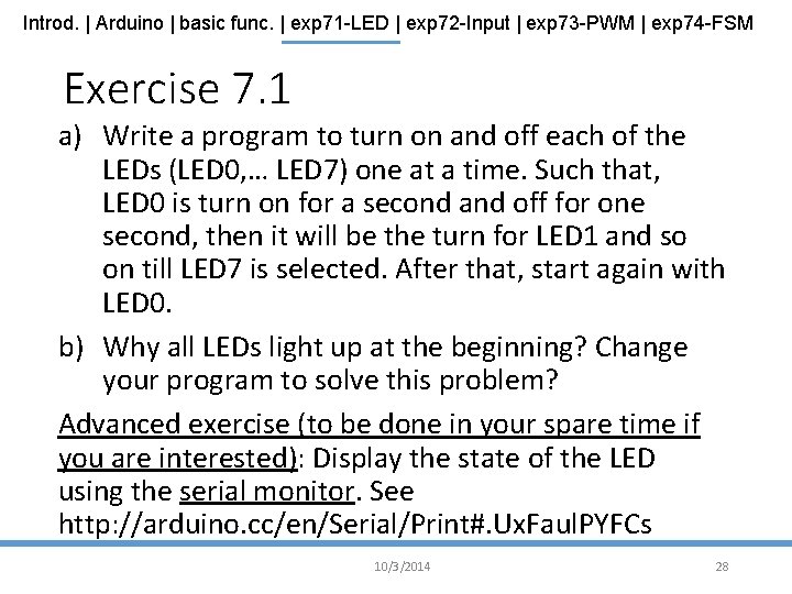
Introd. | Arduino | basic func. | exp 71 -LED | exp 72 -Input | exp 73 -PWM | exp 74 -FSM Exercise 7. 1 a) Write a program to turn on and off each of the LEDs (LED 0, … LED 7) one at a time. Such that, LED 0 is turn on for a second and off for one second, then it will be the turn for LED 1 and so on till LED 7 is selected. After that, start again with LED 0. b) Why all LEDs light up at the beginning? Change your program to solve this problem? Advanced exercise (to be done in your spare time if you are interested): Display the state of the LED using the serial monitor. See http: //arduino. cc/en/Serial/Print#. Ux. Faul. PYFCs 10/3/2014 28
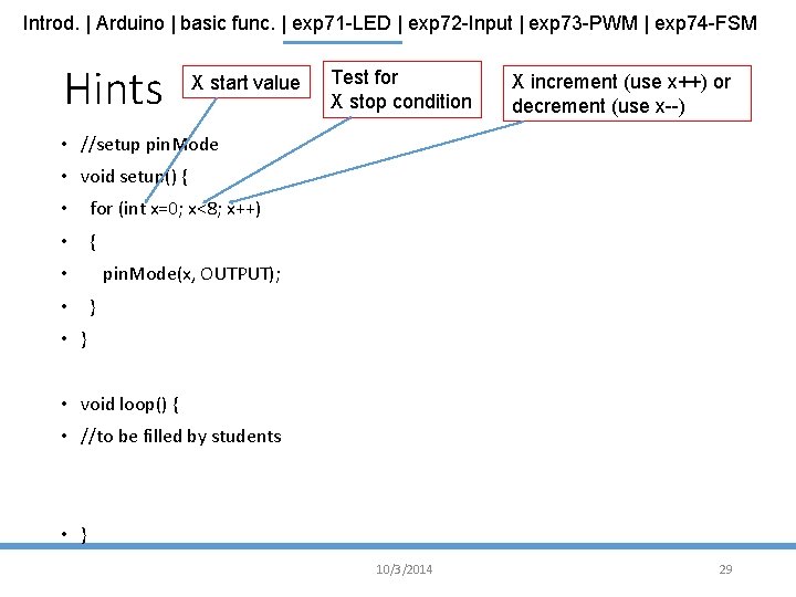
Introd. | Arduino | basic func. | exp 71 -LED | exp 72 -Input | exp 73 -PWM | exp 74 -FSM Hints X start value Test for X stop condition X increment (use x++) or decrement (use x--) • //setup pin. Mode • void setup() { • for (int x=0; x<8; x++) • { pin. Mode(x, OUTPUT); • • } • } • void loop() { • //to be filled by students • } 10/3/2014 29
Introd. | Arduino | basic func. | exp 71 -LED | exp 72 -Input | exp 73 -PWM | exp 74 -FSM Experiment 7. 2: Get Input Use an input value to control an LED 10/3/2014 30
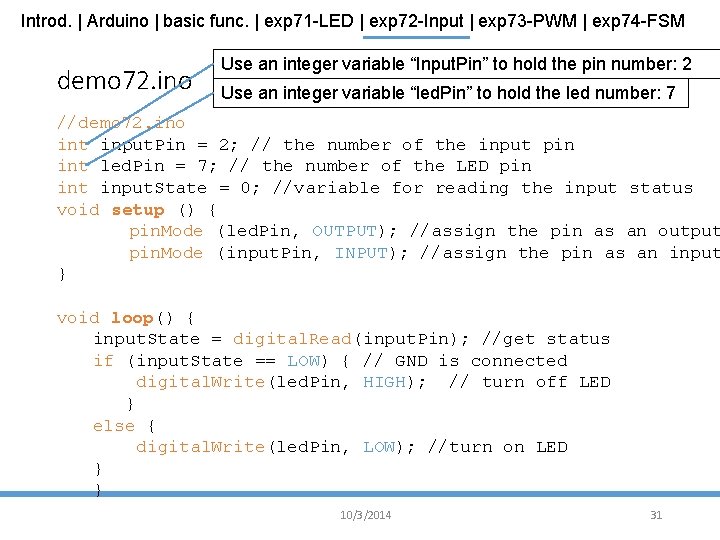
Introd. | Arduino | basic func. | exp 71 -LED | exp 72 -Input | exp 73 -PWM | exp 74 -FSM demo 72. ino Use an integer variable “Input. Pin” to hold the pin number: 2 Use an integer variable “led. Pin” to hold the led number: 7 //demo 72. ino int input. Pin = 2; // the number of the input pin int led. Pin = 7; // the number of the LED pin int input. State = 0; //variable for reading the input status void setup () { pin. Mode (led. Pin, OUTPUT); //assign the pin as an output pin. Mode (input. Pin, INPUT); //assign the pin as an input } void loop() { input. State = digital. Read(input. Pin); //get status if (input. State == LOW) { // GND is connected digital. Write(led. Pin, HIGH); // turn off LED } else { digital. Write(led. Pin, LOW); //turn on LED } } 10/3/2014 31
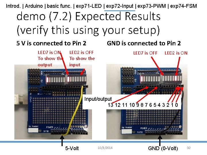
Introd. | Arduino | basic func. | exp 71 -LED | exp 72 -Input | exp 73 -PWM | exp 74 -FSM demo (7. 2) Expected Results (verify this using your setup) 5 V is connected to Pin 2 GND is connected to Pin 2 LED 7 is ON To show the output LED 7 is OFF LED 2 is OFF To show the input LED 2 is ON Input/output 13 12 11 10 9 8 7 6 5 4 3 2 1 0 5 -Volt 10/3/2014 GND (0 -Volt) 32
Introd. | Arduino | basic func. | exp 71 -LED | exp 72 -Input | exp 73 -PWM | exp 74 -FSM Exercise 7. 2 a) Explain what you see after running demo 72. ino b) Modify the code so that the input pin is 3 (instead of 2) and output LED is 6 (instead of 7). Run the code to verify your result. Advanced exercise (to be done in your spare time if you are interested): Use the keyboard of your PC to control the on and off of the LEDS. See http: //arduino. cc/en/Serial/read#. Ux. Fd. TPm. Sx. IE 10/3/2014 33
Introd. | Arduino | basic func. | exp 71 -LED | exp 72 -Input | exp 73 -PWM | exp 74 -FSM Experiment 7. 3: Pulse Width Modulation (PWM) Use PWM to control the intensity an LED 10/3/2014 34
Introd. | Arduino | basic func. | exp 71 -LED | exp 72 -Input | exp 73 -PWM | exp 74 -FSM Pulse Width Modulation (PWM) • PWM is a modulation technique that obtains analog results by digital means • The duration of “ON” is called the pulse_width • Create an analog output by changing the pulse_width for a fixed frequency signal • Can be used to control the speed of a motor • The longer the switch is ON compared to the OFF periods, the higher the power supplied to the load • Advantage: easy to use and implement, low power loss. 10/3/2014 35
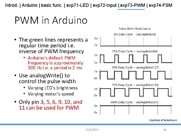
Introd. | Arduino | basic func. | exp 71 -LED | exp 72 -Input | exp 73 -PWM | exp 74 -FSM PWM in Arduino • The green lines represents a regular time period i. e. inverse of PWM frequency • Arduino’s default PWM frequency is approximately 500 Hz i. e. a period is 2 ms • Use analog. Write() to control the pulse width • Varying LED’s brightness • Varying motor’s speed • Only pin 3, 5, 6, 9, 10, and 11 can be used for PWM Courtesy of Arduino. cc 10/3/2014 36
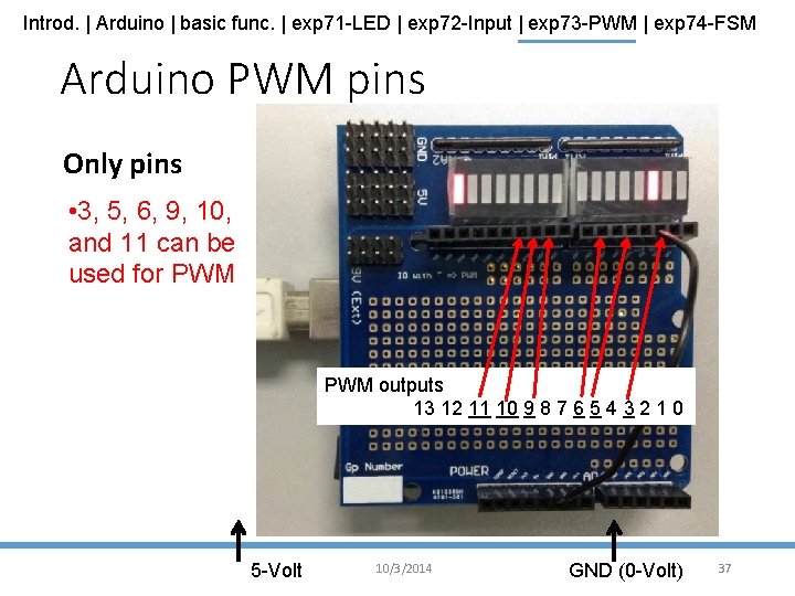
Introd. | Arduino | basic func. | exp 71 -LED | exp 72 -Input | exp 73 -PWM | exp 74 -FSM Arduino PWM pins Only pins • 3, 5, 6, 9, 10, and 11 can be used for PWM outputs 13 12 11 10 9 8 7 6 5 4 3 2 1 0 5 -Volt 10/3/2014 GND (0 -Volt) 37
Introd. | Arduino | basic func. | exp 71 -LED | exp 72 -Input | exp 73 -PWM | exp 74 -FSM analog. Read() • analog. Read() is used to read the value from the specified analog pin • The input voltage between 0 V and 5 V will be mapped into integer values between 0 and 1023 i. e. 4. 9 m. V/unit • Syntax return = analog. Read(pin) • pin: the number of the analog input pin to read from 0 V to 5 V • return: integer from 0 to 1023 10/3/2014 38
Introd. | Arduino | basic func. | exp 71 -LED | exp 72 -Input | exp 73 -PWM | exp 74 -FSM analog. Write() • analog. Write() is used to set the duty cycle of a PWM pulse • After a call to analog. Write(), the pin will generate a steady square wave of the specified duty cycle until the next call to analog. Write(), digital. Read() or digital. Write() on the same pin • Syntax analog. Write(pin, value) • pin: the pin to write to • value: the duty cycle between 0 (always OFF) and 255 (always ON) 10/3/2014 39
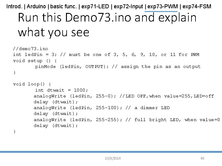
Introd. | Arduino | basic func. | exp 71 -LED | exp 72 -Input | exp 73 -PWM | exp 74 -FSM Run this Demo 73. ino and explain what you see //demo 73. ino int led. Pin = 3; // must be one of 3, 5, 6, 9, 10, or 11 for PWM void setup () { pin. Mode (led. Pin, OUTPUT); // assign the pin as an output } void loop() { int dtwait = 1000; analog. Write (led. Pin, 255 -0); //LED OFF, when value=255, LED=off delay (dtwait); analog. Write (led. Pin, 255 -100); // a dimmer LED delay (dtwait); analog. Write (led. Pin, 255 -255); // full bright LED, when value=0 delay (dtwait); } 10/3/2014 40
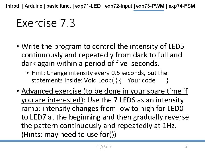
Introd. | Arduino | basic func. | exp 71 -LED | exp 72 -Input | exp 73 -PWM | exp 74 -FSM Exercise 7. 3 • Write the program to control the intensity of LED 5 continuously and repeatedly from dark to full and dark again within a period of five seconds. • Hint: Change intensity every 0. 5 seconds, put the statements inside: Void Loop( ) { Your code } • Advanced exercise (to be done in your spare time if you are interested): Use the 7 LEDS as an intensity ramp: intensity changes from low to high for LED 0 to LED 7 at the beginning and then gradually reverse the pattern continuously and repeatedly at 1 Hz. (Hints: may need to use for()) 10/3/2014 41
Introd. | Arduino | basic func. | exp 71 -LED | exp 72 -Input | exp 73 -PWM | exp 74 -FSM Experiment 7. 4: Finite State Machine (FSM) Use FSM to control a system 10/3/2014 42
Introd. | Arduino | basic func. | exp 71 -LED | exp 72 -Input | exp 73 -PWM | exp 74 -FSM Logic Control • Logic control is an essential part to develop an intelligence device • Logic control can be developed by • Truth table • You only need to know the corresponding input/output relation • As there is no memory, only simple operations can be achieved • Finite State Machine • Decision is based on what it has done i. e. the system has memory, the performance can be more complex 10/3/2014 43
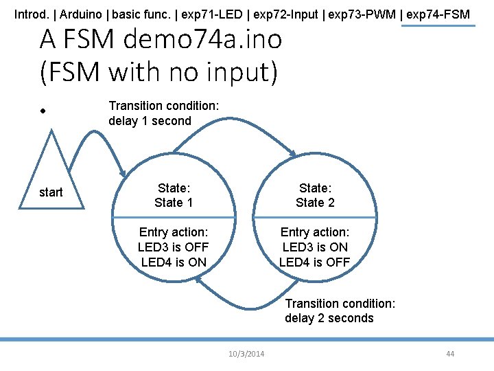
Introd. | Arduino | basic func. | exp 71 -LED | exp 72 -Input | exp 73 -PWM | exp 74 -FSM A FSM demo 74 a. ino (FSM with no input) • start Transition condition: delay 1 second State: State 1 State: State 2 Entry action: LED 3 is OFF LED 4 is ON Entry action: LED 3 is ON LED 4 is OFF Transition condition: delay 2 seconds 10/3/2014 44
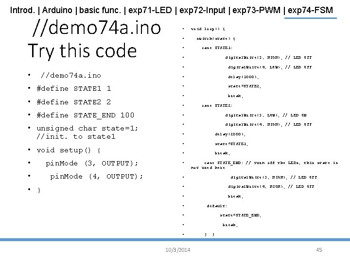
Introd. | Arduino | basic func. | exp 71 -LED | exp 72 -Input | exp 73 -PWM | exp 74 -FSM //demo 74 a. ino Try this code • //demo 74 a. ino • #define STATE 1 1 • #define STATE 2 2 • void loop() { • switch(state) { • case STATE 1: • digital. Write(3, HIGH); // LED OFF • digital. Write(4, LOW); // LED OFF • delay(1000); • state=STATE 2; • break; • case STATE 2: • #define STATE_END 100 • digital. Write(3, LOW); // LED ON • unsigned char state=1; //init. to state 1 • digital. Write(4, HIGH); // LED OFF • void setup() { • • • } pin. Mode (3, OUTPUT); pin. Mode (4, OUTPUT); • delay(2000); • state=STATE 1; • break; • case STATE_END: // turn off the LEDs, this state is not used here • digital. Write(3, HIGH); // LED OFF • digital. Write(4, HIGH); // LED OFF • break; • default: • state=STATE_END; • • 10/3/2014 break; } } 45
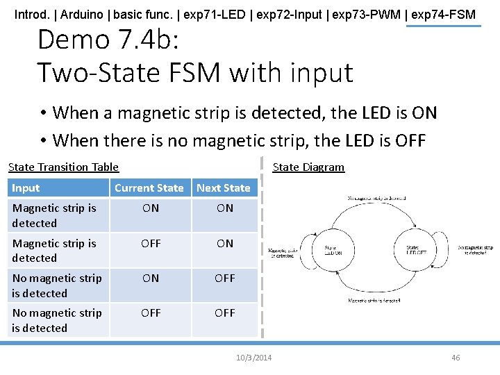
Introd. | Arduino | basic func. | exp 71 -LED | exp 72 -Input | exp 73 -PWM | exp 74 -FSM Demo 7. 4 b: Two-State FSM with input • When a magnetic strip is detected, the LED is ON • When there is no magnetic strip, the LED is OFF State Transition Table Input State Diagram Current State Next State Magnetic strip is detected ON ON Magnetic strip is detected OFF ON No magnetic strip is detected ON OFF No magnetic strip is detected OFF 10/3/2014 46
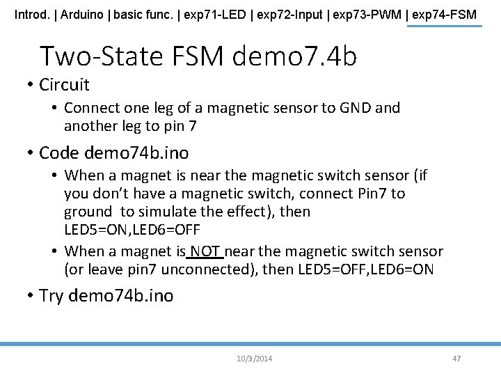
Introd. | Arduino | basic func. | exp 71 -LED | exp 72 -Input | exp 73 -PWM | exp 74 -FSM Two-State FSM demo 7. 4 b • Circuit • Connect one leg of a magnetic sensor to GND and another leg to pin 7 • Code demo 74 b. ino • When a magnet is near the magnetic switch sensor (if you don’t have a magnetic switch, connect Pin 7 to ground to simulate the effect), then LED 5=ON, LED 6=OFF • When a magnet is NOT near the magnetic switch sensor (or leave pin 7 unconnected), then LED 5=OFF, LED 6=ON • Try demo 74 b. ino 10/3/2014 47
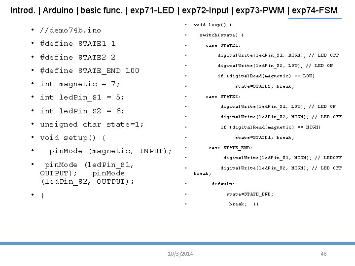
Introd. | Arduino | basic func. | exp 71 -LED | exp 72 -Input | exp 73 -PWM | exp 74 -FSM • • //demo 74 b. ino void loop() { • switch(state) { • #define STATE 1 1 • case STATE 1: • #define STATE 2 2 • digital. Write(led. Pin_S 1, HIGH); // LED OFF • digital. Write(led. Pin_S 2, LOW); // LED ON • if (digital. Read(magnetic) == LOW) • int magnetic = 7; • state=STATE 2; break; • int led. Pin_S 1 = 5; • • int led. Pin_S 2 = 6; • digital. Write(led. Pin_S 1, LOW); // LED ON • digital. Write(led. Pin_S 2, HIGH); // LED OFF • if (digital. Read(magnetic) == HIGH) • #define STATE_END 100 • unsigned char state=1; • void setup() { • • pin. Mode (magnetic, INPUT); pin. Mode (led. Pin_S 1, OUTPUT); pin. Mode (led. Pin_S 2, OUTPUT); • } case STATE 2: state=STATE 1; break; case STATE_END: • digital. Write(led. Pin_S 1, HIGH); // LEDOFF • digital. Write(led. Pin_S 2, HIGH); // LED OFF break; • • • 10/3/2014 default: state=STATE_END; break; }} 48
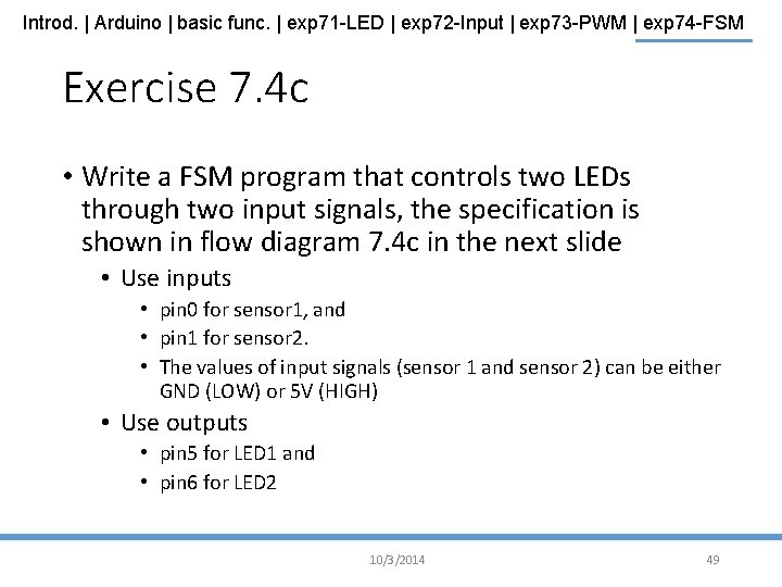
Introd. | Arduino | basic func. | exp 71 -LED | exp 72 -Input | exp 73 -PWM | exp 74 -FSM Exercise 7. 4 c • Write a FSM program that controls two LEDs through two input signals, the specification is shown in flow diagram 7. 4 c in the next slide • Use inputs • pin 0 for sensor 1, and • pin 1 for sensor 2. • The values of input signals (sensor 1 and sensor 2) can be either GND (LOW) or 5 V (HIGH) • Use outputs • pin 5 for LED 1 and • pin 6 for LED 2 10/3/2014 49
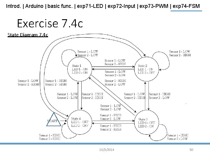
Introd. | Arduino | basic func. | exp 71 -LED | exp 72 -Input | exp 73 -PWM | exp 74 -FSM Exercise 7. 4 c State Diagram 7. 4 c 10/3/2014 50
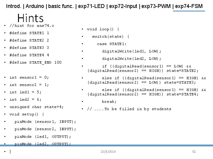
Introd. | Arduino | basic func. | exp 71 -LED | exp 72 -Input | exp 73 -PWM | exp 74 -FSM Hints • //hint for ans 74. c • #define STATE 1 1 • #define STATE 2 2 • #define STATE 3 3 • #define STATE 4 4 • #define STATE_END 100 • int sensor 1 = 0; • int sensor 2 = 1; • int led 1 = 5; • int led 2 = 6; • unsigned char state=4; • void loop() { • switch(state) { • case STATE 1: • digital. Write(led 1, LOW); • digital. Write(led 2, LOW); • if ((digital. Read(sensor 1) == LOW) && (digital. Read(sensor 2) == HIGH)) state=STATE 2; • else if ((digital. Read(sensor 1) == HIGH) && (digital. Read(sensor 2) == LOW)) state=STATE 3; • else if ((digital. Read(sensor 1) == HIGH) && (digital. Read(sensor 2) == HIGH)) state=STATE 4; • break; • // …………To be filled in by students • void setup() { • pin. Mode (sensor 1, INPUT); • pin. Mode (sensor 2, INPUT); • pin. Mode (led 1, OUTPUT); • pin. Mode (led 2, OUTPUT); • } 10/3/2014 51
Introd. | Arduino | basic func. | exp 71 -LED | exp 72 -Input | exp 73 -PWM | exp 74 -FSM Exercise 7. 4 d • Improve the previous exercise with the following conditions • When both LEDs are ON, they should be in full brightness • When either LED is lighted up, the brightness of that LED should be as low as 10 % • Hint use: analog. Write(led 1, 255 -25); //will give 10% LED light 10/3/2014 52
Summary • Learned the use of the Arduino microcontroller digital input / outputs functions some basic functions if-then-else and switch-case control statements in programs • Finite state machines • • 10/3/2014 53
- Slides: 53