l VLSI VeryLargeScale Integration l Todays complex VLSI


.")
 • 1996: Samsung introduced IG DRAM. • 1998: IBM")


 to implement logic")


, Nov. 2002.")


- Slides: 42
l VLSI ¡ Very-Large-Scale Integration l Today’s complex VLSI chips ¡ The number of transistors has exceeded 120 million ¡ Die area is typically about 1 cm 2 l Moore’s low (Gordon Moore, one of the cofounders of the Intel Corporation) ¡ The number of transistors on a chip would double about every 18 months l Design team and design hierarchy are needed to realize a complex chip
l IC ¡ l Integrated circuit ICs have three key advantages over digital circuits built from discrete components ¡ Small size l ¡ High speed l ¡ ICs are much smaller, both transistors and wires are shrunk to micrometer sizes, compared to the centimeter scales of discrete components Communication within a chip is faster than communication between chips on a PCB Low power consumption l Logic operations within a chip take much less power
Milestones for IC Industry ˙ 1947: Bardeen, Brattain & Shockly invented the transistor, foundation of the IC industry. ˙ 1952: SONY introduced the first transistor-based radio. ˙ 1958: Kilby invented integrated circuits (ICs). ˙ 1965: Moore’s law. ˙ 1968: Noyce and Moore founded Intel. ˙ 1970: Intel introduced 1 K DRAM.
Milestones for IC Industry ˙ 1971: Intel announced 4 -bit 4004 microprocessors (2250 transistors). ˙ 1976/81: Apple II/IBM PC. ˙ 1984: Xilinx invented FPGA’s. ˙ 1985: Intel began focusing on microprocessor products. ˙ 1987: TSMC was founded (fabless IC design). ˙ 1991: ARM introduced its first embeddable RISC IP core (chipless IC design).
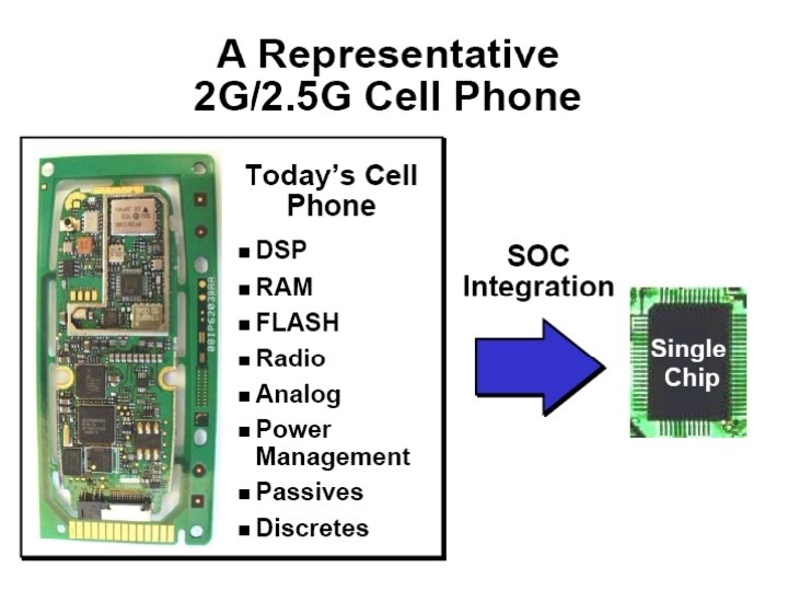
Milestones for IC Industry (Cont’d) • 1996: Samsung introduced IG DRAM. • 1998: IBM announces 1 GHz experimental microprocessor. • 1999/earlier: System-on-Chip (SOC) applications. • 2002/earlier: System-in-Package (SIP) technology. • An Intel P 4 processor contains 42 million transistors (1 billion by 2005) • Today, we produce > 30 million transistors person (1 billion/person by 2008).
Technology Evolution
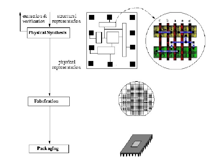
IC Design & Manufacturing Process
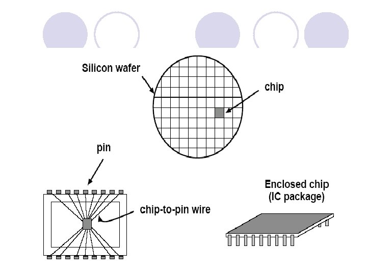
From Wafer to Chip
Wafer
Manufacturing Flow
CPU Evolution
32 -bit CPU 80386
Traditional VLSI Design Cycle
IC Design Considerations Several conflicting considerations: 1. Design Complexity: large number of devices/transistors 2. Performance: optimization requirements for high performance 3. Time-to-market: about a 15% gain for early birds 4. Cost: die area, packaging, testing, etc. 5. Others: power, signal integrity (noise, etc), testability, reliability, manufacturability, etc.
Nanometer Design Challenges ˙ In 2005, feature size ≈ 0. 1 µm, µP frequency ≈ 3. 5 GHz, die size ≈ 520 mm 2, µP transistor count per chip ≈ 200 M, wiring level ≈ 8 layers, supply voltage ≈ 1 V, power consumption ≈ 160 W. Feature size sub-wavelength lithography (impacts of process variation)? noise? wire coupling? reliability? Frequency , dimension effects? timing closure? Chip complexity Supply voltage Wiring level interconnect delay? Electromagnetic field large-scale system design methodology? signal integrity (noise, IR drop, etc)? manufacturability? 3 D layout? Power consumption power & thermal issues?
Sub-wavelength Lithography Causes Problems!!
Sub-wavelength Lithography Causes Problems!!
Problems with 10 -layer metal?
Reliability Is Another Big Problem!!
Design Styles ˙Specific design styles shall require specific CAD tools
SSI/SPLD Design Style
Full Custom Design Style • Designers can control the shape of all mask patterns. • Designers can specify the design up to the level of individual transistors.
Standard Cell Design Style • Selects pre-designed cells (of same height) to implement logic
Standard Cell Example
Gate Array Design Style • Prefabricates a transistor array • Needs wiring customization to implement logic
FPGA Design Style ˙Logic and interconnects are both prefabricated. ˙Illustrated by a symmetric array-based FPGA
Comparisons of Design Styles
Design Style Trade-offs
Technology Roadmap for Semiconductors ˙ Source: International Technology Roadmap for Semiconductors (ITRS), Nov. 2002. http: //www. itrs. net/ntrs/publntrs. nsf. ˙ Deep submicron technology: node (feature size) < 0. 25 µm. ˙Nanometer Technology: node < 0. 1 µm.
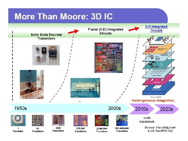
3 D IC Design 3 D IC technology is to stack multiple device layers into a monolithic chip. It has several advantages listed as follows: Higher integration density: it can place more elements into one single package using much smaller area than a traditional 2 D IC. Heterogeneous integration: it can integrate disparate technologies, such as logic circuit, memory, and mixed signal components. Higher performance: it can significantly reduce the wirelength. Lower power: it can lower power consumption especially that for the clock net because of shorter wire-length.
3 D IC Design l Three kinds of fabrication technologies to implement 3 D IC ¡ Package-on-Package : it integrates packaged ICs into a new package. ¡ 3 D die stacking with wire bonding: it integrates bare dice into the same package which are connected by wire bonding. ¡ 3 D IC integration with TSV: it partitions integrated circuits into several dice and stacks the dice into a single package. Stack dice are connected by using through-silicon-vias (TSVs).
3 D IC Design
3 D IC Design
3 D IC Design
3 D IC Design
l Q&A
l Thanks for l Your Attention