
L 16 Testbenches for state machines VHDL Language
L 16 – Testbenches for state machines
VHDL Language Elements o More examples n n o HDL coding of class examples Testbench for example Testing of examples – testbench construction n Note trade off and difference in Mealy vs Moore implementation from simulation results o Constructing simple testbenches – general rules o Ref: text Unit 10, 17, 20 9/2/2012 – ECE 3561 Lect 9 Copyright 2012 - Joanne De. Groat, ECE, OSU 2
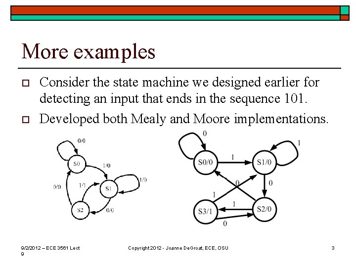
More examples o o Consider the state machine we designed earlier for detecting an input that ends in the sequence 101. Developed both Mealy and Moore implementations. 9/2/2012 – ECE 3561 Lect 9 Copyright 2012 - Joanne De. Groat, ECE, OSU 3
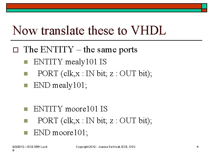
Now translate these to VHDL o The ENTITY – the same ports n n n ENTITY mealy 101 IS PORT (clk, x : IN bit; z : OUT bit); END mealy 101; ENTITY moore 101 IS PORT (clk, x : IN bit; z : OUT bit); END moore 101; 9/2/2012 – ECE 3561 Lect 9 Copyright 2012 - Joanne De. Groat, ECE, OSU 4
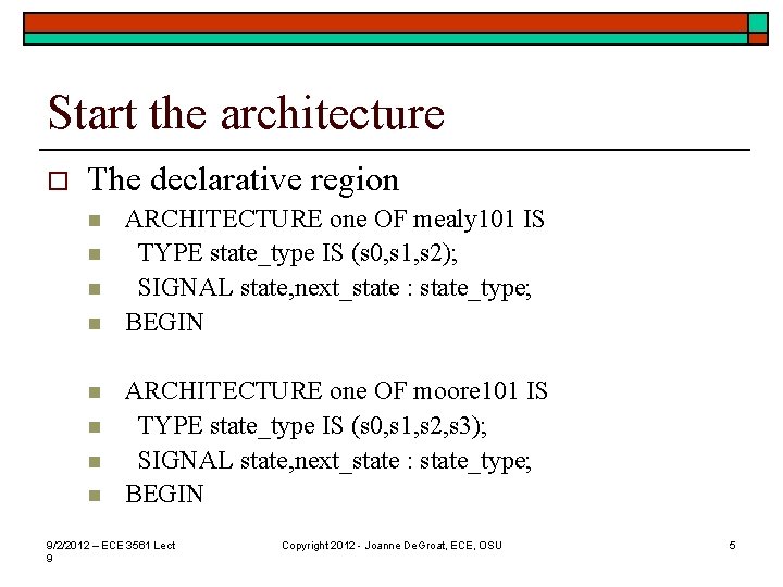
Start the architecture o The declarative region n n n n ARCHITECTURE one OF mealy 101 IS TYPE state_type IS (s 0, s 1, s 2); SIGNAL state, next_state : state_type; BEGIN ARCHITECTURE one OF moore 101 IS TYPE state_type IS (s 0, s 1, s 2, s 3); SIGNAL state, next_state : state_type; BEGIN 9/2/2012 – ECE 3561 Lect 9 Copyright 2012 - Joanne De. Groat, ECE, OSU 5
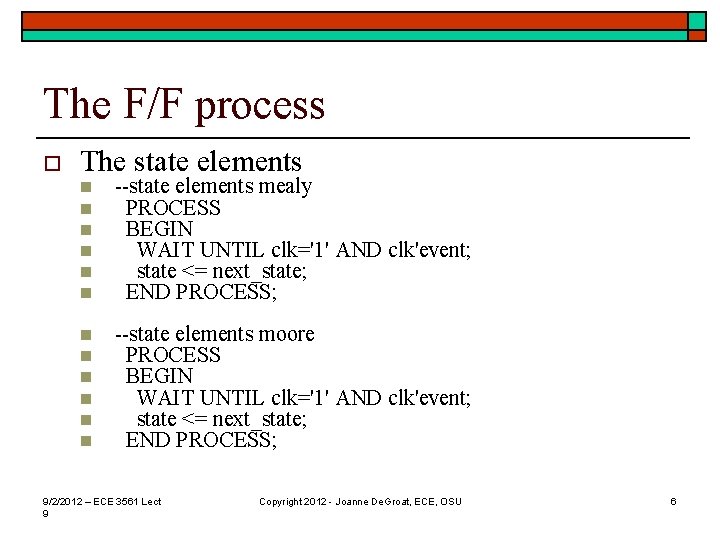
The F/F process o The state elements n n n --state elements mealy PROCESS BEGIN WAIT UNTIL clk='1' AND clk'event; state <= next_state; END PROCESS; n n n --state elements moore PROCESS BEGIN WAIT UNTIL clk='1' AND clk'event; state <= next_state; END PROCESS; 9/2/2012 – ECE 3561 Lect 9 Copyright 2012 - Joanne De. Groat, ECE, OSU 6
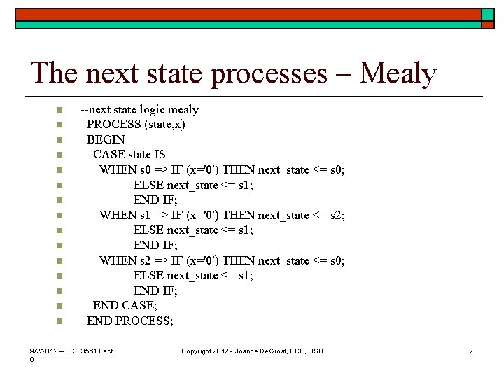
The next state processes – Mealy n n n n --next state logic mealy PROCESS (state, x) BEGIN CASE state IS WHEN s 0 => IF (x='0') THEN next_state <= s 0; ELSE next_state <= s 1; END IF; WHEN s 1 => IF (x='0') THEN next_state <= s 2; ELSE next_state <= s 1; END IF; WHEN s 2 => IF (x='0') THEN next_state <= s 0; ELSE next_state <= s 1; END IF; END CASE; END PROCESS; 9/2/2012 – ECE 3561 Lect 9 Copyright 2012 - Joanne De. Groat, ECE, OSU 7
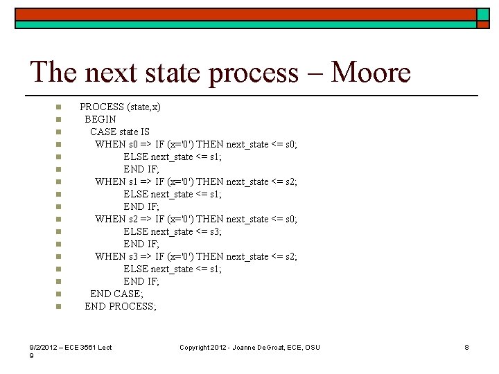
The next state process – Moore n n n n n PROCESS (state, x) BEGIN CASE state IS WHEN s 0 => IF (x='0') THEN next_state <= s 0; ELSE next_state <= s 1; END IF; WHEN s 1 => IF (x='0') THEN next_state <= s 2; ELSE next_state <= s 1; END IF; WHEN s 2 => IF (x='0') THEN next_state <= s 0; ELSE next_state <= s 3; END IF; WHEN s 3 => IF (x='0') THEN next_state <= s 2; ELSE next_state <= s 1; END IF; END CASE; END PROCESS; 9/2/2012 – ECE 3561 Lect 9 Copyright 2012 - Joanne De. Groat, ECE, OSU 8
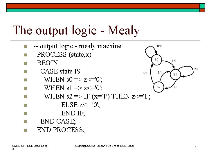
The output logic - Mealy n n n -- output logic - mealy machine PROCESS (state, x) BEGIN CASE state IS WHEN s 0 => z<='0'; WHEN s 1 => z<='0'; WHEN s 2 => IF (x='1') THEN z<='1'; ELSE z<= '0'; END IF; END CASE; END PROCESS; 9/2/2012 – ECE 3561 Lect 9 Copyright 2012 - Joanne De. Groat, ECE, OSU 9
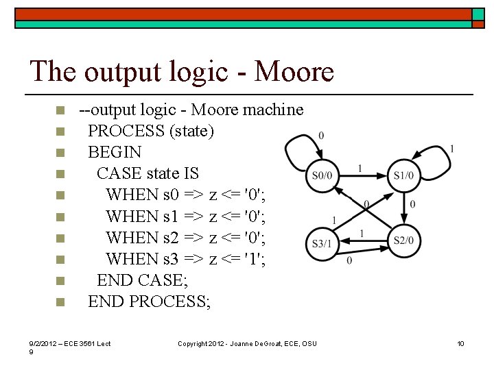
The output logic - Moore n n n n n --output logic - Moore machine PROCESS (state) BEGIN CASE state IS WHEN s 0 => z <= '0'; WHEN s 1 => z <= '0'; WHEN s 2 => z <= '0'; WHEN s 3 => z <= '1'; END CASE; END PROCESS; 9/2/2012 – ECE 3561 Lect 9 Copyright 2012 - Joanne De. Groat, ECE, OSU 10
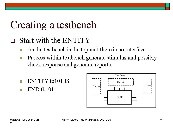
Creating a testbench o Start with the ENTITY n n As the testbench is the top unit there is no interface. Process within testbench generate stimulus and possibly check response and generate reports. ENTITY tb 101 IS END tb 101; 9/2/2012 – ECE 3561 Lect 9 Copyright 2012 - Joanne De. Groat, ECE, OSU 11
Declarations o The declrative region – declare DUTs n n n n n ARCHITECTURE one OF tb 101 IS --declare units to be tested COMPONENT mealy 101 PORT (clk, x : IN bit; z : OUT bit); END COMPONENT; FOR all : mealy 101 USE ENTITY work. mealy 101(one); COMPONENT moore 101 PORT (clk, x : IN bit; z : OUT bit); END COMPONENT; FOR all : moore 101 USE ENTITY work. moore 101(one); 9/2/2012 – ECE 3561 Lect 9 Copyright 2012 - Joanne De. Groat, ECE, OSU 12
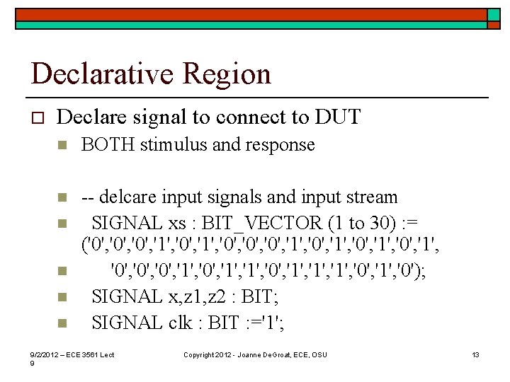
Declarative Region o Declare signal to connect to DUT n BOTH stimulus and response n -- delcare input signals and input stream SIGNAL xs : BIT_VECTOR (1 to 30) : = ('0', '0', '1', '0', '1', '0', '1', '0', '1', '0'); SIGNAL x, z 1, z 2 : BIT; SIGNAL clk : BIT : ='1'; n n 9/2/2012 – ECE 3561 Lect 9 Copyright 2012 - Joanne De. Groat, ECE, OSU 13
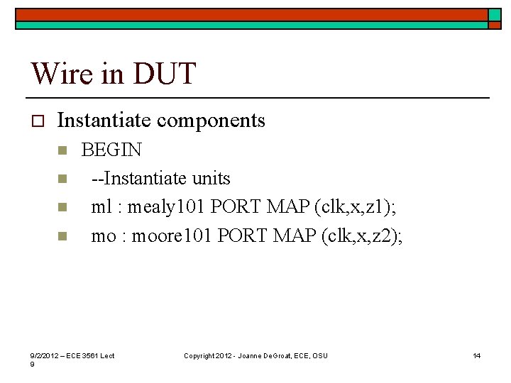
Wire in DUT o Instantiate components n n BEGIN --Instantiate units ml : mealy 101 PORT MAP (clk, x, z 1); mo : moore 101 PORT MAP (clk, x, z 2); 9/2/2012 – ECE 3561 Lect 9 Copyright 2012 - Joanne De. Groat, ECE, OSU 14
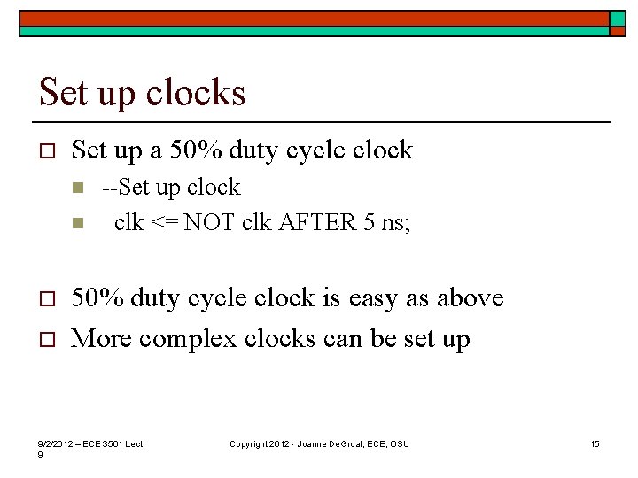
Set up clocks o Set up a 50% duty cycle clock n n o o --Set up clock clk <= NOT clk AFTER 5 ns; 50% duty cycle clock is easy as above More complex clocks can be set up 9/2/2012 – ECE 3561 Lect 9 Copyright 2012 - Joanne De. Groat, ECE, OSU 15
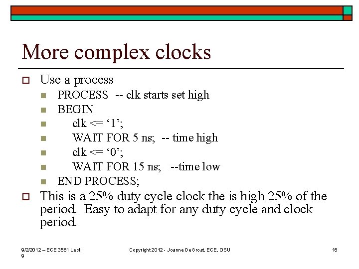
More complex clocks o Use a process n n n n o PROCESS -- clk starts set high BEGIN clk <= ‘ 1’; WAIT FOR 5 ns; -- time high clk <= ‘ 0’; WAIT FOR 15 ns; --time low END PROCESS; This is a 25% duty cycle clock the is high 25% of the period. Easy to adapt for any duty cycle and clock period. 9/2/2012 – ECE 3561 Lect 9 Copyright 2012 - Joanne De. Groat, ECE, OSU 16
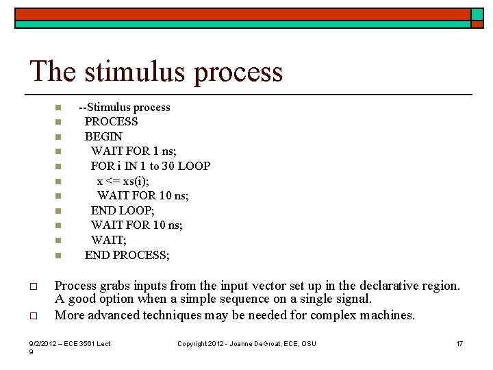
The stimulus process n n n o o --Stimulus process PROCESS BEGIN WAIT FOR 1 ns; FOR i IN 1 to 30 LOOP x <= xs(i); WAIT FOR 10 ns; END LOOP; WAIT FOR 10 ns; WAIT; END PROCESS; Process grabs inputs from the input vector set up in the declarative region. A good option when a simple sequence on a single signal. More advanced techniques may be needed for complex machines. 9/2/2012 – ECE 3561 Lect 9 Copyright 2012 - Joanne De. Groat, ECE, OSU 17
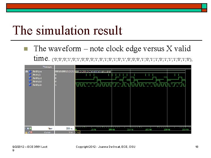
The simulation result n The waveform – note clock edge versus X valid time. ('0', '0', '1', '0', '1', '0', '1‘, '0', '1', '0', '1', '0'); 9/2/2012 – ECE 3561 Lect 9 Copyright 2012 - Joanne De. Groat, ECE, OSU 18
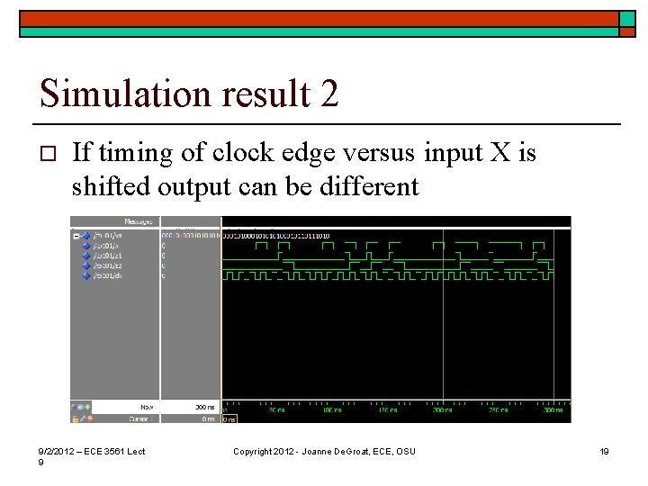
Simulation result 2 o If timing of clock edge versus input X is shifted output can be different 9/2/2012 – ECE 3561 Lect 9 Copyright 2012 - Joanne De. Groat, ECE, OSU 19
Demo of simulation o o A look at a live demonstration of Model Sim for simulation of this machine. Note that in Moore implementation output seems to be delayed ~1 clock. 9/2/2012 – ECE 3561 Lect 9 Copyright 2012 - Joanne De. Groat, ECE, OSU 20
Lecture summary o HDL from code to simulation n o For the 101 sequence detector Testbench for the sequence detector 9/2/2012 – ECE 3561 Lect 9 Copyright 2012 - Joanne De. Groat, ECE, OSU 21
- Slides: 21