Kuliah Mikrokontroler AVR Contoh TimerCounterPWM AVR ATmega 16


 Mode Fast PWM Mode Phase")


 saat inisialisasi Isi counter akan naik sampai mencapai")
 RPWM = 256 (resolusi PWM, 8 bit)")


 Mode Perhitungan pewaktuan lebih tepat, karena mekanisme re-clear")
 saat inisialisasi 255 Isi counter akan naik")


 ? Berapa frekuensi tertinggi")


 Mode Fast PWM Mode Phase")


 Mode")


 Mode Fast PWM Mode Phase")

 Mode")


- Slides: 42
Kuliah Mikrokontroler AVR Contoh Timer-Counter-PWM AVR ATmega 16 Eru©Oktober 2009 PENS
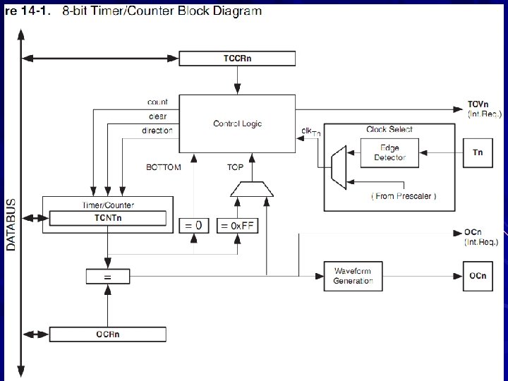
8 -bit Timer/Counter 0 with PWM Features – Single Compare Unit Counter – Clear Timer on Compare Match (Auto Reload) – Glitch-free, Phase Correct Pulse Width Modulator (PWM) – Frequency Generator – External Event Counter – 10 -bit Clock Prescaler – Overflow and Compare Match Interrupt Sources (TOV 0 and OCF 0)
Modes Normal Mode Clear Timer on Compare Match (CTC) Mode Fast PWM Mode Phase Correct PWM Mode
Normal Mode – TOP = FFH Clock Source – System Clock Timer – T 0 Pin (Falling/Rising Edge) Counter Prescaller (System Clock, Timer) – Stop, fclock/1, fclock/8, fclock/64, fclock/256, fclock/1024 Output, OC 0 – – Disconnect Toggle on Compare Match Clear on Compare Match Set on Compare Match Interrupt – – Overflow saat TCNT 0 menjadi 0 Compare Match Value – Timer Value, TCNT 0 – Compare Match Value, OCR 0
Counter 0 Buat program untuk menghitung jumlah barang menggunakan sensor optotransistor dan peraga LCD + + PC T 0 ATmega 16 LCD
Jumlah digit = 3 + ASCIIZ Inisialisasi Tanpa static, tiap perulangan tmp akan di-create ulang
Timer 0 Hampir selalu, timer berkaitan dengan interupsi Buat program pembangkit multi-channel PWM (8 channel) menggunakan timer 0 dan PORTB Data PWM pada variable – unsigned char PWM[8] Frekuensi PWM sekitar 100 Hz dengan f clock 4 MHz – Untuk eksitasi motor atau sejenisnya
Prinsip Timer diberi nilai awal (Load) saat inisialisasi Isi counter akan naik sampai mencapai FFH dan kembali ke 00 H Saat isi timer/counter kembali ke 00 H akan muncul interupsi TOV 0 Pada rutin interupsi, nilai awal counter diisi kembali (Reload) Interupsi Timer Overflow td 255 Nilai Timer Naik nd Nilai Awal (inisialisasi) Re. Load 0 t. TOV 0
Persiapan FPWM = 100 Hz (frekuensi PWM) RPWM = 256 (resolusi PWM, 8 bit) FTOV 0 = 256 x 100 Hz = 25, 600 k. Hz (f clock PWM) Fclock = 4 MHz (f clock timer/counter) ? Pembagi = 4 MHz / 25, 6 k. Hz = 156. 25 157 clock Pembagi = Prescaller x Hitungan Counter Prescaller = 1 (dipilih) Hitungan Counter = 157 clock TCNT 0 awal = 256 - 157 = 99 (63 H) Menggunakan Interupsi Timer 0 Over Flow (TOV 0)
Hasil Simulasi : 173 clock per interupsi Atau f. TOV 0 23, 121 k. Hz Mengapa ? Inisialisasi
Sampai proses Re. Load, butuh beberapa clock Kesalahan Perhitungan Loncat, butuh sekitar 1 clock Hasil Simulasi : 173 clock per interupsi Atau f. TOV 0 23, 121 k. Hz Mengapa ? td nd tx nx t. TOV 0 Diperlukan waktu saat terjadi interupsi, loncat ke rutin interupsi, sampai titik nilai TCNT 0 diisi ulang (sekitar 16 clock sistem, menurut simulasi) Solusi, pilih frekuensi timer serendah mungkin untuk mengurangi efek loncatan
Tugas Buat pembangkit gelombang kotak dengan frekuensi 1 k. Hz melalui – Port sembarang – Pin OC 0 (menggunakan register OCR 0)
Clear Timer on Compare Match (CTC) Mode Perhitungan pewaktuan lebih tepat, karena mekanisme re-clear terjadi secara otomatis pada level hardware Contoh, buat aplikasi PWM seperti pada uraian sebelumnya
Prinsip Timer diberi nilai awal (00 H) saat inisialisasi 255 Isi counter akan naik sampai mencapai Nilai Timer OCR 0 dan kembali Naik ke 00 H secara otomatis Saat isi Nilai Awal timer/counter (inisialisasi) mencapai OCR 0 akan muncul interupsi OC 0 Pin OC 0 dapat 0 digunakan untuk membangkitkan gelombang tertentu Interupsi OC 0 td reclear Nilai OCR 0 nd t. OC 0
Persiapan FPWM = 100 Hz RPWM = 256 FOC 0 = 256 x 100 Hz = 25, 600 k. Hz Fclock = 4 MHz Pembagi = 4 MHz / 25, 6 k. Hz = 156. 25 Prescaller = 1 OCR 0 = 157 -1 = 156 (9 CH) Menggunakan Interupsi OC 0
Inisialisasi Waktu yang dicapai 157 ± 1 clock Dari mana ± 1 clock ? Lebih akurat dari mode Normal – Mengapa ?
Fast PWM Mode Buat program untuk membangkitkan gelombang PWM dengan duty cycle 25% dan frekuensi PWM 20 k. Hz melalui pin OC 0 AVR ATmega 16
Persiapan FPWM = 20 k. Hz RPWM = 256 FClock. PWM = 20 k. Hz x 256 = 5, 12 MHz FClock. CPU = 4 MHz Prescaller = 1 Ditentukan (mengapa ? ) – FClock. PWM = 4 MHz – FPWM = 4 MHz / 256 = 15. 625 k. Hz OCR 0 = 25% x 255 = 63 = 3 FH
Inisialisasi
Contoh Buat program untuk menghasilkan gelombang sinus dengan frekuensi 100 Hz dan amplitudo 2 volt OC 0 AVR ATmega 16
Persiapan FSinyal = 100 Hz FSampling > 2 x 100 Hz 4 k. Hz – mengapa ? FPWM >> FSampling 20 k. Hz – Mengapa ? FClock. CPU = 4 MHz Prescaller = 1 Ditentukan – FClock. PWM = 4 MHz – FPWM = 4 MHz / 256 = 15. 625 k. Hz
Inisialisasi Apakah keluaran dari sistem ini berupa tegangan bolak-balik (ac) ? Berapa frekuensi tertinggi yang dapat dihasilkan dengan cara ini ? Bagaimana caranya untuk mendapatkan frekuensi gelombang lebih dari beberapa k. Hz ? – Misalkan untuk audio 15 ~ 20 k. Hz
Phase Correct PWM Mode Buat program untuk membangkitkan gelombang PWM dengan duty cycle 25% dan frekuensi PWM 10 k. Hz melalui pin OC 0 AVR ATmega 16
Persiapan FPWM = 10 k. Hz RPWM = 256 FClock. PWM = 10 k. Hz x 256 x 2 = 5, 12 MHz FClock. CPU = 4 MHz Prescaller = 1 Ditentukan – FClock. PWM = 4 MHz – FPWM = 4 MHz / (2 x 256) = 7. 8125 k. Hz OCR 0 = 25% x 255 = 63 = 3 FH
Phase Correct PWM Mode Inisialisasi
16 -bit Timer/Counter 1 Features – – – True 16 -bit Design (i. e. , Allows 16 -bit PWM) Two Independent Output Compare Units Double Buffered Output Compare Registers One Input Capture Unit Input Capture Noise Canceler Clear Timer on Compare Match (Auto Reload) Glitch-free, Phase Correct Pulse Width Modulator (PWM) Variable PWM Period Frequency Generator External Event Counter Four Independent Interrupt Sources (TOV 1, OCF 1 A, OCF 1 B, and ICF 1)
Modes Normal Mode Clear Timer on Compare Match (CTC) Mode Fast PWM Mode Phase Correct PWM Mode Phase and Frequency Correct PWM Mode
Operasi 16 Bit
Normal Mode
Clear Timer on Compare Match (CTC) Mode
Frequency Counter
Tachometer
Fast PWM Mode
Phase Correct PWM Mode
Phase and Frequency Correct PWM Mode
8 -bit Timer/Counter 2 with PWM and Asynchronous Operation Features – Single Compare unit Counter – Clear Timer on Compare Match (Auto Reload) – Glitch-free, Phase Correct Pulse Width Modulator (PWM) – Frequency Generator – 10 -bit Clock Prescaler – Overflow and Compare Match Interrupt Sources (TOV 2 and OCF 2) – Allows clocking from External 32 k. Hz Watch Crystal Independent of the I/O Clock
Modes Normal Mode Clear Timer on Compare Match (CTC) Mode Fast PWM Mode Phase Correct PWM Mode
Normal Mode
Clear Timer on Compare Match (CTC) Mode
Fast PWM Mode
Phase Correct PWM Mode