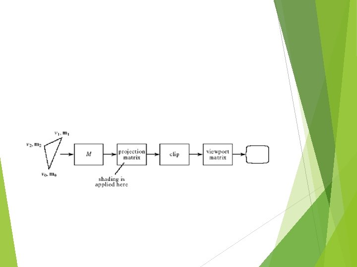
KNOWLEDGE INSTITUTE OF TECHNOLOGY Department of Computer Science


 of light) Shape Direction Object Properties Material")


")


 R+L=2 N(N. L) R = 2 N(N.")


; 2. Set up Light properties gl.")


 per triangle Color")


- Slides: 58
KNOWLEDGE INSTITUTE OF TECHNOLOGY Department of Computer Science and Engineering CS 6504 - COMPUTER GRAPHICS UNIT 4 - Lighting and Shading Prepared by Dr. J. Gowrishankar, ASP/CSE
Outline • Lighting models • Ambient • Diffuse • Specular • Surface Rendering Methods • Ray-Tracing
What we know We already know how to render the world from a viewpoint.
ILLUMINATION Illumination - the transport of light from a source to a point via direct and indirect paths Lighting - computing the luminous intensity for a specified 3 D point, given a viewpoint Shading - assigning colors to pixels Illumination Models: Empirical - approximations to observed light properties Physically based - applying physics properties of light and its interactions with matter
Two components Light Source Properties Color (Wavelength(s) of light) Shape Direction Object Properties Material Geometry Absorption
Light Source Properties Color We usually assume the light has one wavelength Shape point light source approximate the light source as a 3 D point in space. Light rays emanate in all directions. good for small light sources (compared to the scene) far away light sources
Distributed Lights Light Source Shape continued distributed light source approximating the light source as a 3 D object. Light rays usually emanate in specific directions good for larger light sources area light sources
Light Source Direction In computer graphics, we usually treat lights as rays emanating from a source. The direction of these rays can either be: Omni-directional (point light source) Directional (spotlights)
Contributions from lights & its Positions We will breakdown what a light does to an object into three different components. This APPROXIMATES what a light does. To actually compute the rays is too expensive to do in real-time. Light at a pixel from a light = Ambient + Diffuse + Specular contributions. Ilight = Iambient + Idiffuse + Ispecular
Ambient Term - Background Light The ambient term is a HACK! It represents the approximate contribution of the light to the general scene, regardless of location of light and object Indirect reflections that are too complex to completely and accurately compute Iambient = color
Diffuse Term Contribution that a light has on the surface, regardless of viewing direction. Diffuse surfaces, on a microscopic level, are very rough. This means that a ray of light coming in has an equal chance of being reflected in any direction. What are some ideal diffuse surfaces?
Lambert’s Cosine Law Diffuse surfaces follow Lambert’s Cosine Law - reflected energy from a small surface area in a particular direction is proportional to the cosine of the angle between that direction and the surface normal. Think about surface area and # of rays
To determine how much of a diffuse contribution a light supplies to the surface, we need the surface normal and the direction on the incoming ray What is the angle between these two vectors? Idiffuse = kd. Ilightcos = kd. Ilight(N. L) Ilight kd = diffuse (intensity) of light [0. . 1] = surface diffuse reflectivity What How CS are L and N in? expensive is it?
Example What are the possible values for theta (and thus the dot product? ) http: //graphics. lcs. mit. edu/classes/6. 837/F 98/Lecture 18/ Slide 11. html
Specular Reflection Specular contribution can be thought of as the “shiny highlight” of a plastic object. On a microscopic level, the surface is very smooth. Almost all light is reflected. What is an ideal purely specular reflector? What does this term depend on? Viewing Direction Normal of the Surface
Snell’s Law Specular reflection applies Snell’s Law. · The incoming ray, the surface normal, and the reflected ray all lie in a common plane. · The angle that the reflected ray forms with the surface normal is determined by the angle that the incoming ray forms with the surface normal, and the relative speeds of light of the mediums in which the incident and reflected rays propagate according to: · We assume l = r
Snell’s Law is for IDEAL surfaces Think about the amount of light reflected at different angles. N R L V
Different for shiny vs. dull objects
Snell’s Law is for IDEAL surfaces • Think about the amount of light reflected at different angles. N R L V
Phong Model Phong Reflection Model An approximation is sets the intensity of specular reflection proportional to (cos )shininess What are the possible values of cos ? What does the value of shininess mean? How do we represent shinny or dull surfaces using the Phong model? What is the real thing we probably SHOULD do? Ispecular = ks. Ilight (cos )shininess = ks. Ilight (V. R)shininess
Effect of the shininess value
How do we compute R? N*(N. L) R+L=2 N(N. L) R = 2 N(N. L)-L L N R N(N. L) L V
Simplify this Instead of R, we compute halfway between L and V. H We call this vector the halfway vector, H. L R N V
Let’s compare the two H R N Q: Which vectors stay constant when viewpoint is far away? A: V and L vectors -> H Q: What does this buy us? L V
Ambient - the combination of light reflections from various surfaces to produce a uniform illumination. Background light. Diffuse - uniform light scattering of light rays on a surface. Proportional to the “amount of light” that hits the surface. Depends on the surface normal and light vector. Specular - light that gets reflected. Depends on the light ray, the viewing angle, and the surface normal.
Ambient + Diffuse + Specular
Lighting Equation Ilambient = light source l’s ambient component Ildiffuse = light source l’s diffuse component Ilspecular = light source l’s specular component kambient = surface material ambient reflectivity N R L kdiffuse = surface material diffuse reflectivity kspecular = surface material specular reflectivity shininess = specular reflection parameter (1 -> dull, 100+ -> very shiny) V
Clamping & Spotlights What does the value Ifinal mean? How do we make sure it doesn’t get too high? Spotlights? How do them? N R L V
How would we light a green cube? N R L V
Attenuation One factor we have yet to take into account is that a light source contributes a higher incident intensity to closer surfaces. The energy from a point light source falls off proportional to 1/d 2. What happens if we don’t do this?
What would attenuation do for: Actually, using only 1/d 2, makes it difficult to correctly light things. Think if d=1 and d=2. Why? Remember, we are approximating things. Lighting model is too simple AND most lights are not point sources. We use:
Subtleties What’s wrong with: What’s a good fix?
Full Illumination Model Run demo
Putting Lights in Open. GL 1. gl. Enable(GL_LIGHTING); 2. Set up Light properties gl. Lightf(…) 3. Set up Material properties gl. Material(…)
Shading When do we do the lighting equation? What is the cost to compute the lighting for a 3 D point?
Shading is how we “color” a triangle. Constant Shading Gouraud Shading Phong Shading
Constant Shading Constant One Intensity or Flat Shading color for the entire triangle Fast Good for some objects What happens if triangles are small? Sudden intensity changes at borders
Flat Shading Fast and simple. Compute the color of a polygon. Use that color on every pixel of the polygon.
Gouraud Shading Intensity Interpolation Shading Calculate lighting at the vertices. Then interpolate the colors as you scan convert
Gouraud Shading Relatively fast, only do three calculations No sudden intensity changes What can it not do? What are some approaches to fix this? Question, what is the normal at a vertex?
Compute SA, SB, SC for triangle ABC. Si = shade of point i. For a scanline XY, compute SX, SY by lerping. e. g. t. AB = |AX| / |AB|. SA = t. AB* SA + (1 -t. AB)*SB Compute SP B By lerping between SX and SY. X A P SX Y SP scanline SY C
Phong Shading Interpolate the normal, since that is the information that represents the “curvature” Linearly interpolate the vertex normals. For each pixel, as you scan convert, calculate the lighting per pixel. True “per pixel” lighting Not done by most hardware/libraries/etc
Phong illumination model: I = Ambient + Diffuse + Specular = Ia + Id + Is = ka La + kd Ld l • n + ks Ls (r • v)a May add light attenuation term 1/(a+bd+cd 2) ( ka La + kd l • n Ld) + ks Ls (r • v)a Parameters needed: Light: La, Ld, Ls for each light Surface: ka, kd, ks, a Repeat for each color component, light source
Shading Techniques Constant Shading Calculate one lighting calculation (pick a vertex) per triangle Color the entire triangle the same color Gouraud Shading Calculate three lighting calculations (the vertices) per triangle Linearly interpolate the colors as you scan convert Phong Shading While you scan convert, linearly interpolate the normals. With the interpolated normal at each pixel, calculate the lighting at each pixel
Wireframe Model Example:
Boundary Representation Example
Space Partitioning Representation Example
HALFTONE & DITHERING PATTERNS Halftoning The process of generating a binary pattern of black and white dots from an image is termed halftoning. In traditional newspaper and magazine production, this process is carried out photographically by projection of a transparency through a 'halftone screen' onto film. The screen is a glass plate with a grid etched into it. Different screens can be used to control the size and shape of the dots in the halftoned image
A fine grid, with a 'screen frequency' of 200‑ 300 lines per inch, gives the image quality necessary for magazine production. A screen frequency of 85 lines per inch is deemed acceptable for newspapers.
1. 1 Patterning A simple digital halftoning technique known as patterning involves replacing each pixel by a pattern taken from a 'binary font'. Figure 5. 1 shows such a font, made up of ten 3 x 3 matrices of pixels. This font can be used to print an image consisting of ten grey levels
Fig. 1. 1. A 3 x 3 binary font for printing a grayscale.
A pixel with a grey level of 0 is replaced by a matrix containing no white pixels; a pixel with a grey level of 1 is replaced by a matrix containing a single white pixel; and so on. Note that, since we are replacing each pixel by a 3 x 3 block of pixels, both the width and the height of the image increase by a factor of 3.
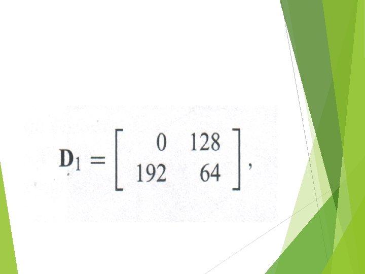
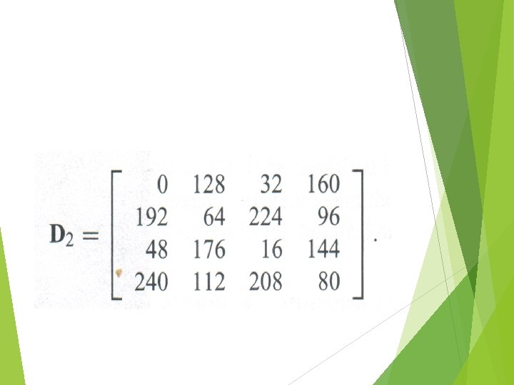
1. 2 Dithering Another technique for digital halftoning is dithering. Dithering can be accomplished by thresholding the image against a dither matrix. Dithering is a technique used in computer graphics to create the illusion of color depth in images with a limited color palette (color quantization) The first two dither matrices, rescaled for application to 8‑bit images, are
The elements of a dither matrix are thresholds. The matrix is laid like a tile over the entire image and each pixel value is compared with the corresponding threshold from the matrix. The pixel becomes white if its value exceeds the threshold or black otherwise. This approach produces an output image with the same dimensions as the input image, but with less detail visible.
Algorithm to halftone an image using a dither matrix: for all x & y do if f(x, y) > m(x, y) then g(x, y) = white else g(x, y) = black end if End for