KNIFEEDGE DIFFRACTION q Huygens principle All points on


 (�)=2 π/λ*∆ If Obstruction is very close")


- Slides: 13
KNIFE-EDGE DIFFRACTION q. Huygen's principle: All points on a wave front can be considered as points for the production of secondary wavelets, which subsequently combined to produce new waves in new directions. q. Hence, even if a region is shadowed by an obstruction, diffraction around the object's edges produces waves that propagate into the shadowed region. q. Points above the obstruction can be considered secondary sources of wavelets, which combine to form waves propagating toward the receiver to the right of the screen.
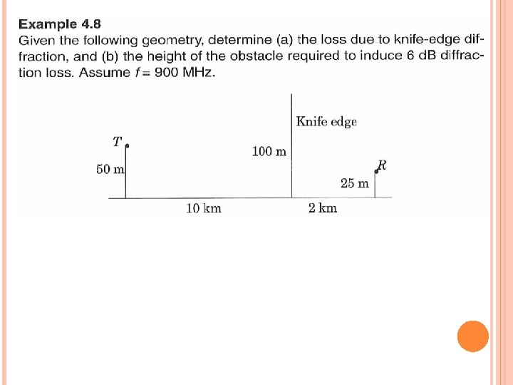
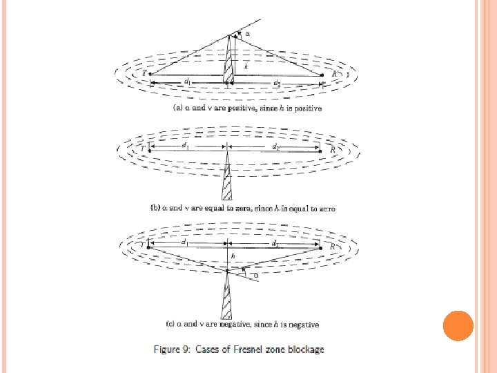
α and β are not necessarily equal as d 1≠d 2. For large d 1; d 2, we can assume ht = hr for simplification with condition that d 1 and d 2 > >h If obstruction is very close to receiver, d 1 > >d 2
Electric field from the diffracted path strongly depends on the path difference between the length of the diffracted path and the length of the LOS path.
90°
α Phase Difference(Electrical length of path difference) (�)=2 π/λ*∆ If Obstruction is very close to Receiver Fresnel-Kirchoff parameter where v is essentially the height of the screen multiplied by a frequencydependent scalar.
The normalized electric field produced at the receiver, relative to the LOS path (free space field) is, Here, the variable t is used to obtain the resulting expression as a function of v.
The Diffraction Gain due to presence of knife edge, as compared to free space E-field is given by,
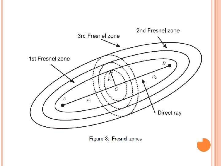
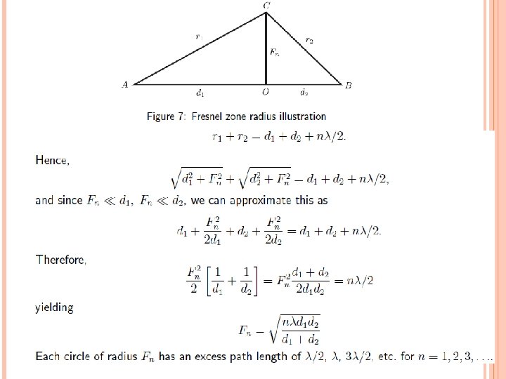
FRESNEL ZONES If the height h is chosen such that the path length difference between the diffracted path and LOS path ∆ is one halfwavelength (λ/2), the diffracted wave has incurred a 180 degree phase shift relative to the LOS wave. This is true over a locus of point forming a ring in the plane of the screen. Such a ring or circle is called a Fresnel zone. This process repeats, giving us alternating Fresnel zones that provide constructive and destructive interference to the total received signal every λ/2 increase in h.
Fn depends on the distances d 1 and d 2 to the obstruction Fn is maximum when d 1 = d 2. The circles shrink as the obstruction is moved closer to the transmitter or receiver. Fresnel zones are elliptical in shape with the Transmitter and Receiver antenna at their foci. If an obstruction doesn’t block the volume contained within the first Fresnel zone, the diffraction loss will be minimal and can be neglected. If about 55% of the first Fresnel zone is clear then further Fresnel zone clearance doesn’t significantly alter the diffraction loss.