Kinematics Grasping Goal understand ideal robot mechanisms Robot

Kinematics & Grasping Goal : understand ideal robot mechanisms Robot positions and shapes as a function of control parameters – kinematics Need to know: • Representing mechanism geometry • Standard configurations • Degrees of freedom • Grippers and graspability conditions
")
3 D Coordinate Systems Left handed (Right handed reverses +Z direction)

Vectors & Points in 3 D Point Vector
 coordinates • Global (untranslated)")
Local Reference Frames can be expressed as • Local (translated) coordinates • Global (untranslated) coordinates Local could also have further sub-local frames

Translations Move to

Rotations Rotate about Z axis A lot of conventions Here: positive is anti-clockwise when looking along +Z • in local (rotated) coordinates is (a, b, c)’ • in global (unrotated) coordinates is (a cos( )-b sin( ), a sin( )+b cos( ), c)’

Rotation Matrix Representation I Much more compact and clearer

Rotation Matrix Representation II

Other Rotation Representations All equivalent but different parameters: • Yaw, pitch, roll • Azimuth, elevation, twist • Axis + angle • Slant, tilt, twist • Quaternion

Full Rotation Specification • Need 3 angles for arbitrary 3 D rotation • Lock & key example • Rotation angles : • Warning: rotation order by convention but must be used consistently:

Full Transformation Specification Each connection has a new local coordinate system Need to specify 6 degrees of freedom 3 rotation + 3 translation

Kinematic Chains is at: In C 2: In C 1: In C 0:

Homogeneous Coordinates I Messy when more than 2 links, as in robot So: pack rotation and translation into Homogeneous coordinate matrix Extend points with a 1 from 3 -vector to 4 -vector Extend vectors with a 0 from 3 -vector to 4 -vector Pack rotation and translation into 4 x 4 matrix: 3 rotation parameters: 3 translation parameters:

Homogeneous coordinates II In C 2: In C 1: In C 0: Longer chains for robot arms (e. g. 6 links):

Adding Joints Prismatic joint: sliding structures parameterize one translation direction per joint E. g. : slides in the X direction Revolute joint: rotates parameterize one rotation angle per joint

Degrees of Freedom • Controllable Do. F: number of joints • Effective Do. F: number of Do. F you can get after multiple motions car has 2 controllable (move, turn) but can adjust XY position and orientation so 3 effective Do. F • Task Do. F: configurations in space dimensionality: 2 D : 3 (x, y, angle) 3 D : 6 (x, y, z, 3 angles)

Forward and Inverse Kinematics Forward: Given joint angles, find gripper position Easy for sequential joints in robot arm: just multiply matrices Inverse: Given desired gripper position, find joint angles Hard for sequential joints – geometric reasoning

Configuration Space I Alternative representation to scene coordinates Number of joints=J J-dimensional space Binary encoding: 0: invalid pose, 1: free space Real encoding: “distance” from goal configuration Point in C. S = configuration in real space Curve in C. S. = motion path in real space

Configuration Space II

Sequential & Parallel Mechanisms Simplified into 2 D Serial manipulator vary: Parallel manipulator vary:
 Inverse (position->param) Easy (just multiply matrices) Hard")
Computing Positions & Parameters Serial Forward (param->position) Inverse (position->param) Easy (just multiply matrices) Hard (messy robot specific geometry) Parallel Hard (messy robot specific geometry) Easy (just read off lengths from gripper position)

SPECIFYING ROBOT POSITIONS 1. Actuator level: specify voltages that generate required joint angles. 2. Joint level: specify joint angles and let system calculate voltages. 3. Effector level: specify tool position and let system compute joint angles. 4. Task level: specify the required task and let the system compute the sequence of tool positions Most robot programming is at level 2 or 3.

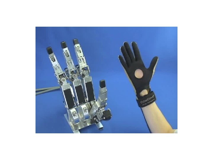
Grippers and Grasping • Gripper: special tool for general part manipulation • Fingers/gripper: 2, 3, 5 • Joints/finger: 1, 2, 3 Your hand: 5 fingers * 3 Do. F + wrist position (6) = 21 Do. F. Whew!
 1 opposable finger Do. F: 4 fingers")
Barret Hand 2 parallel fingers (spread uniformly) 1 opposable finger Do. F: 4 fingers (2 finger joints bend uniformly)

Barret Hand

Finger Contact Geometry Coefficient of friction at fingertip: Surface normal: direction perpendicular to surface: Friction cone: angles within about surface normal Force direction: direction finger pushed No-slip condition:

Force Closure Need balanced forces or else object twists 2 fingers – forces oppose: 3 fingers – forces meet at point: Force closure: point where forces meet lies within 3 friction cones otherwise object slips

Other Grasping Criteria Some heuristics for a good grasp: • Contact points form nearly equilateral triangle • Contact points make a big triangle • Force focus point near centre-of-mass

Grasp Algorithm 1. Isolate boundary 2. Locate large enough smooth graspable sections 3. Compute surface normals 4. Pick triples of grasp points 5. Evaluate for closure & select by heuristics 6. Evaluate for reachability and collisions 7. Compute force directions and amount 8. Plan approach and finger closing strategy 9. Contact surface & apply grasping force 10. Lift (& hope)

Kinematics Summary 1. 2. 3. 4. 5. Need vector & matrix form for robot geometry Geometry of joints & joint parameters Forward & inverse kinematics Degrees of freedom Grippers & grasping conditions
- Slides: 31