
Kansas Light Source and its Application in Single
- Slides: 44
Kansas Light Source and its Application in Single Attosecond Pulses Generation Bing Shan J. R. Macdonald Laboratory Physics Department, Kansas State University 5/12/2004, Atomic Physics Seminar, KSU
Outline A high-output, high efficiency femtosecond laser based on a single-stage multipass amplifier (CLEO 2004, ITu. I 15, 5/18/2004, 13: 00 pm) Bing Shan, Chun Wang, and Zenghu Chang • Control signal beam sizes to get high gain without damage • In cavity Pockels cell to suppress ASE • Supported researches and experiments in J. R. Macdonald Lab Generation of XUV Supercontinuum and Single Attosecond Pulses by Half-cycle Polarization Gating (CLEO 2004, JMA 5, 5/17/2004, 9: 30 am) Bing Shan, Shambhu Ghimire, and Zenghu Chang • Ellipticity varying pulse • Polarization gating in high-order harmonic generation • Generate single attosecond pulse and XUV supercontinuum 5/12/2004, Atomic Physics Seminar, KSU
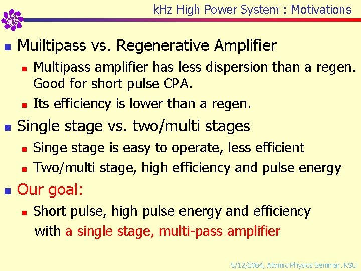
k. Hz High Power System : Motivations n Muiltipass vs. Regenerative Amplifier n n n Single stage vs. two/multi stages n n n Multipass amplifier has less dispersion than a regen. Good for short pulse CPA. Its efficiency is lower than a regen. Singe stage is easy to operate, less efficient Two/multi stage, high efficiency and pulse energy Our goal: n Short pulse, high pulse energy and efficiency with a single stage, multi-pass amplifier 5/12/2004, Atomic Physics Seminar, KSU
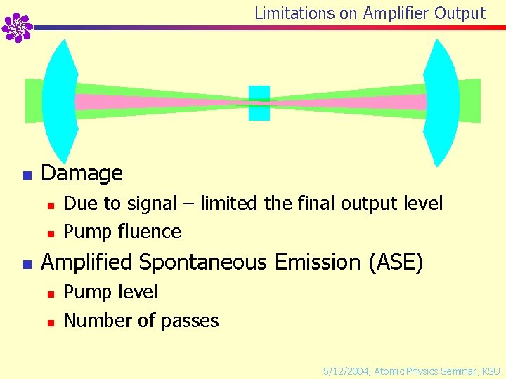
Limitations on Amplifier Output n Damage n n n Due to signal – limited the final output level Pump fluence Amplified Spontaneous Emission (ASE) n n Pump level Number of passes 5/12/2004, Atomic Physics Seminar, KSU
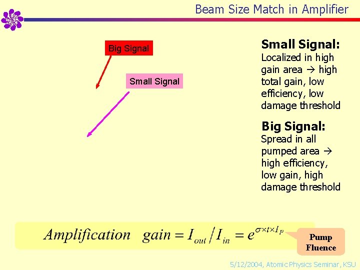
Beam Size Match in Amplifier Big Signal Small Signal: Localized in high gain area high total gain, low efficiency, low damage threshold Big Signal: Spread in all pumped area high efficiency, low gain, high damage threshold Pump Fluence 5/12/2004, Atomic Physics Seminar, KSU
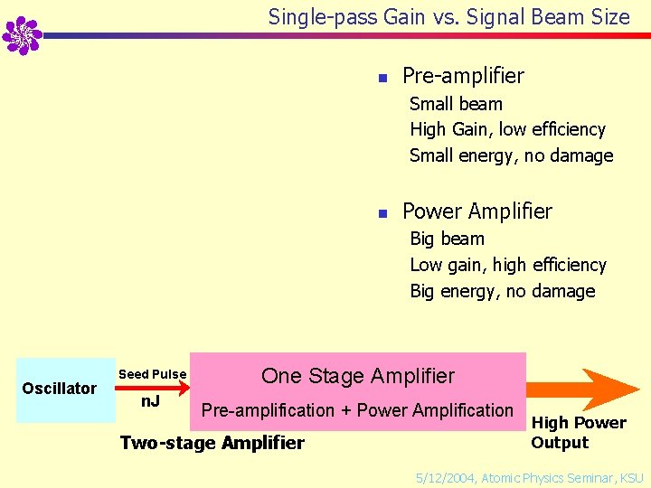
Single-pass Gain vs. Signal Beam Size n Pre-amplifier Small beam High Gain, low efficiency Small energy, no damage n Power Amplifier Big beam Low gain, high efficiency Big energy, no damage Oscillator Seed Pulse n. J Pre-amplifier Power Amplifier One Stage Amplifier Gain 105 ~ 106 Gain 100 µJ ~m. J 10 s m. J Pre-amplification + Power Amplification Two-stage Amplifier High Power Output 5/12/2004, Atomic Physics Seminar, KSU
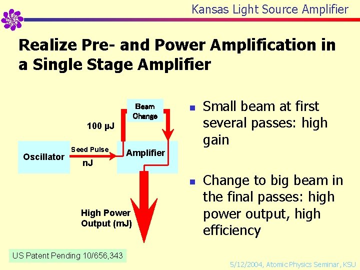
Kansas Light Source Amplifier Realize Pre- and Power Amplification in a Single Stage Amplifier Beam Change n 100 µJ Oscillator Seed Pulse Small beam at first several passes: high gain Amplifier n. J n High Power Output (m. J) US Patent Pending 10/656, 343 Change to big beam in the final passes: high power output, high efficiency 5/12/2004, Atomic Physics Seminar, KSU
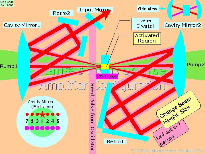
Bing Shan Feb. 2003 Retro 2 Input Mirror Side View Laser Crystal Cavity Mirror 1 Cavity Mirror 2 Activated Region Pump 1 Kansas Light Source Amplifier Configuration Pump 2 rd st Pass 2 3 1 nd Pass 7 5 31 2 4 6 Seed Pulse from Oscillator Cavity Mirror 1 (End view) Retro 1 am e e B ize g an t, S h C igh He 7 t in u o d Le ses s pa 5/12/2004, Atomic Physics Seminar, KSU
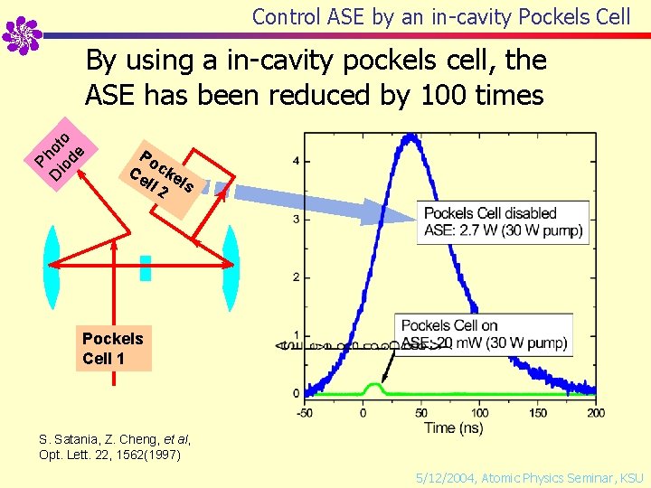
Control ASE by an in-cavity Pockels Cell D io Ph ot de o By using a in-cavity pockels cell, the ASE has been reduced by 100 times Po Ce cke ll 2 ls Pockels Cell 1 S. Satania, Z. Cheng, et al, Opt. Lett. 22, 1562(1997) 5/12/2004, Atomic Physics Seminar, KSU
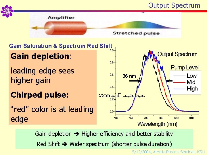
Output Spectrum Gain Saturation & Spectrum Red Shift Gain depletion: leading edge sees higher gain 36 nm Chirped pulse: “red” color is at leading edge Gain depletion Higher efficiency and better stability Red Shift Wider spectrum (shorter pulse duration) 5/12/2004, Atomic Physics Seminar, KSU
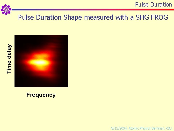
Pulse Duration Time delay Pulse Duration Shape measured with a SHG FROG Frequency 5/12/2004, Atomic Physics Seminar, KSU
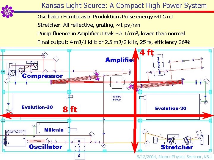
Kansas Light Source: A Compact High Power System Oscillator: Femto. Laser Produktion, Pulse energy ~0. 5 n. J Stretcher: All reflective, grating, ~1 ps/nm Pump fluence in Amplifier: Peak ~5 J/cm 2, lower than normal Final output: 4 m. J/1 k. Hz or 2. 5 m. J/2 k. Hz, 25 fs, efficiency 26% 4 ft 8 ft 5/12/2004, Atomic Physics Seminar, KSU
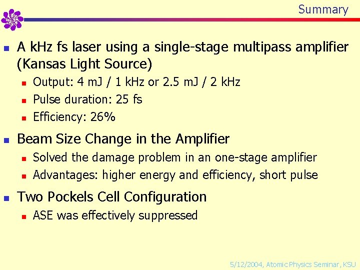
Summary n A k. Hz fs laser using a single-stage multipass amplifier (Kansas Light Source) n n Beam Size Change in the Amplifier n n n Output: 4 m. J / 1 k. Hz or 2. 5 m. J / 2 k. Hz Pulse duration: 25 fs Efficiency: 26% Solved the damage problem in an one-stage amplifier Advantages: higher energy and efficiency, short pulse Two Pockels Cell Configuration n ASE was effectively suppressed 5/12/2004, Atomic Physics Seminar, KSU
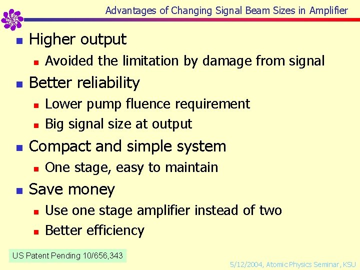
Advantages of Changing Signal Beam Sizes in Amplifier n Higher output n n Better reliability n n n Lower pump fluence requirement Big signal size at output Compact and simple system n n Avoided the limitation by damage from signal One stage, easy to maintain Save money n n Use one stage amplifier instead of two Better efficiency US Patent Pending 10/656, 343 5/12/2004, Atomic Physics Seminar, KSU
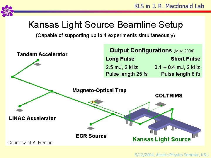
KLS in J. R. Macdonald Lab Kansas Light Source Beamline Setup (Capable of supporting up to 4 experiments simultaneously) Tandem Accelerator Output Configurations (May 2004) Long Pulse Short Pulse 2. 5 m. J, 2 k. Hz Pulse length 25 fs Magneto-Optical Trap 0. 1 + 0. 4 m. J, 2 k. Hz Pulse length 8 fs COLTRIMS LINAC Accelerator ECR Source Courtesy of Al Rankin Kansas Light Source 5/12/2004, Atomic Physics Seminar, KSU
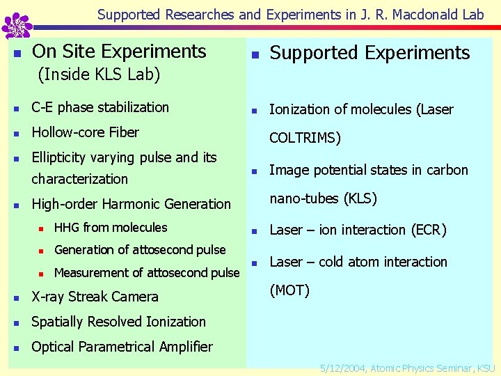
Supported Researches and Experiments in J. R. Macdonald Lab n On Site Experiments n Supported Experiments n Ionization of molecules (Laser (Inside KLS Lab) n C-E phase stabilization n Hollow-core Fiber n Ellipticity varying pulse and its characterization n COLTRIMS) n nano-tubes (KLS) High-order Harmonic Generation n HHG from molecules n Generation of attosecond pulse n Measurement of attosecond pulse n X-ray Streak Camera n Spatially Resolved Ionization n Optical Parametrical Amplifier Image potential states in carbon n Laser – ion interaction (ECR) n Laser – cold atom interaction (MOT) 5/12/2004, Atomic Physics Seminar, KSU
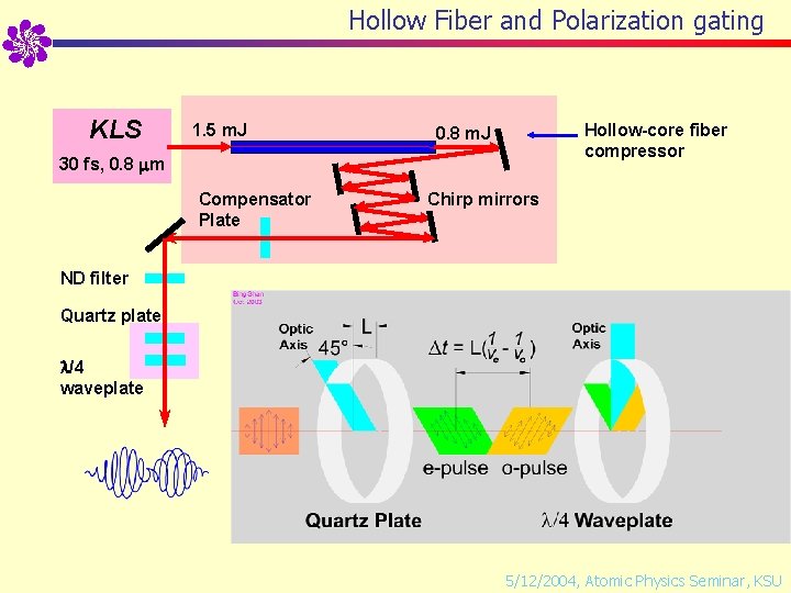
Hollow Fiber and Polarization gating KLS 1. 5 m. J Hollow-core fiber compressor 0. 8 m. J 30 fs, 0. 8 m Compensator Plate Chirp mirrors ND filter Quartz plate /4 waveplate 5/12/2004, Atomic Physics Seminar, KSU
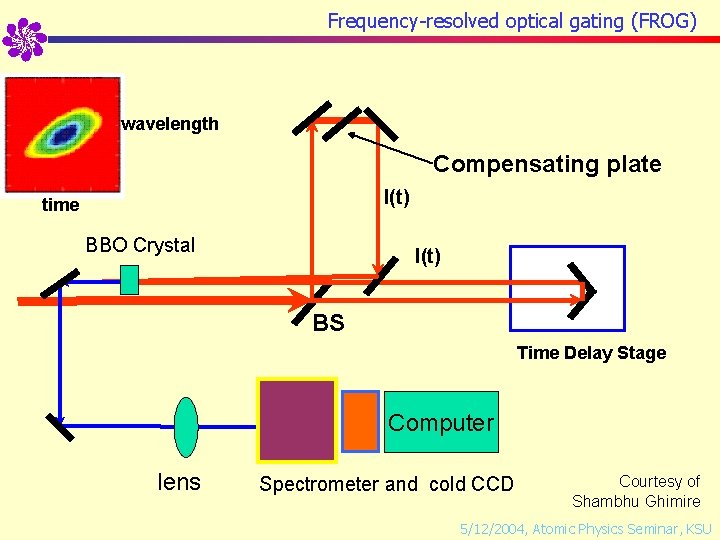
Frequency-resolved optical gating (FROG) wavelength Compensating plate I(t) time BBO Crystal I(t) BS Time Delay Stage Computer lens Spectrometer and cold CCD Courtesy of Shambhu Ghimire 5/12/2004, Atomic Physics Seminar, KSU
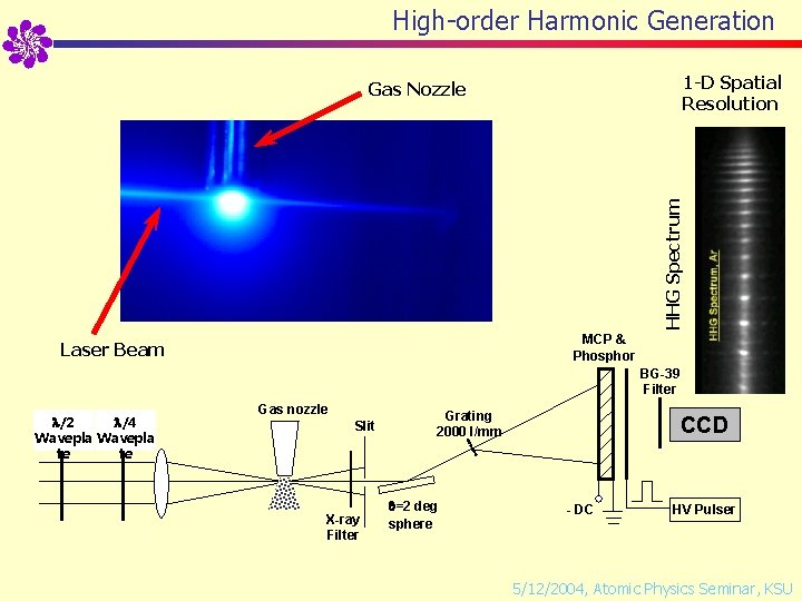
High-order Harmonic Generation 1 -D Spatial Resolution HHG Spectrum Gas Nozzle MCP & Phosphor Laser Beam BG-39 Filter /2 /4 Wavepla te te Gas nozzle Slit X-ray Filter Grating 2000 l/mm =2 deg sphere CCD - DC HV Pulser 5/12/2004, Atomic Physics Seminar, KSU
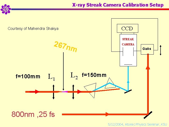
X-ray Streak Camera Calibration Setup CCD Courtesy of Mahendra Shakya STREAK CAMERA 267 n m f=100 mm L 1 L 2 Ga. As f=150 mm 800 nm , 25 fs 5/12/2004, Atomic Physics Seminar, KSU
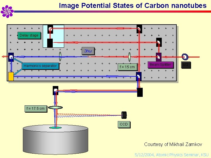
Image Potential States of Carbon nanotubes Delay stage 3 hω Harmonics separator f = 15 cm Beam Splitter λ/2 f = 17. 5 cm CCD Courtesy of Mikhail Zamkov 5/12/2004, Atomic Physics Seminar, KSU
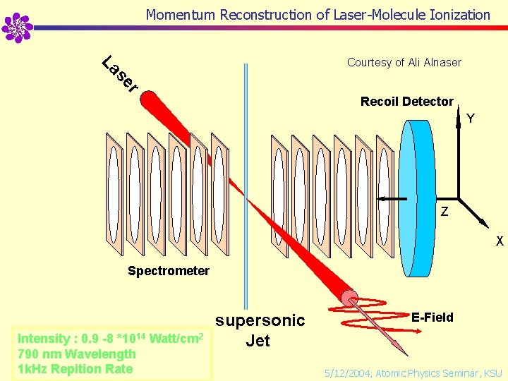
Momentum Reconstruction of Laser-Molecule Ionization r se La Courtesy of Ali Alnaser Recoil Detector Y Z X Spectrometer Intensity : 0. 9 -8 *1014 Watt/cm 2 790 nm Wavelength 1 k. Hz Repition Rate supersonic Jet E-Field 5/12/2004, Atomic Physics Seminar, KSU
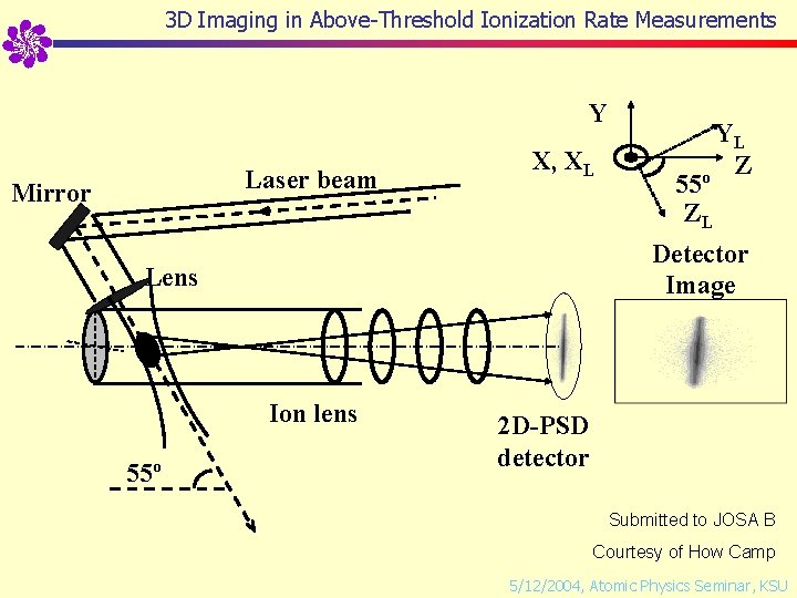
3 D Imaging in Above-Threshold Ionization Rate Measurements Y Laser beam Mirror X, XL Detector Image Lens Ion lens 55 o YL o Z 55 ZL 2 D-PSD detector Submitted to JOSA B Courtesy of How Camp 5/12/2004, Atomic Physics Seminar, KSU
Generation of XUV Supercontinuum and Single Attosecond Pulses by Half-cycle Gating Bing Shan, Shambhu Ghimire, and Zenghu Chang J. R. Macdonald Laboratory Physics Department, Kansas State University 5/12/2004, Atomic Physics Seminar, KSU
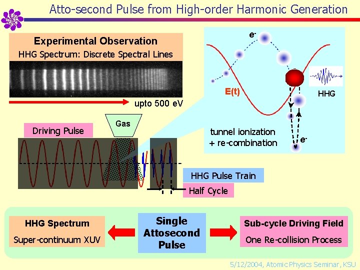
Atto-second Pulse from High-order Harmonic Generation e- Experimental Observation HHG Spectrum: Discrete Spectral Lines E(t) HHG upto 500 e. V Driving Pulse Gas tunnel ionization + re-combination e- HHG Pulse Train Half Cycle HHG Spectrum Super-continuum XUV Single Attosecond Pulse Sub-cycle Driving Field One Re-collision Process 5/12/2004, Atomic Physics Seminar, KSU
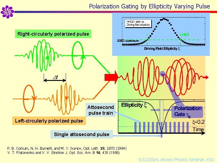
Polarization Gating by Ellipticity Varying Pulse e. Right-circularly polarized pulse e. HHG e- t Attosecond pulse train Left-circularly polarized pulse Single attosecond pulse P. B. Corkum, N. H. Burnett, and M. Y. Ivanov, Opt. Lett. 19, 1870 (1994) V. T. Platonenko and V. V. Strelkov J. Opt. Soc. Am. B 16, 435 (1999) 5/12/2004, Atomic Physics Seminar, KSU
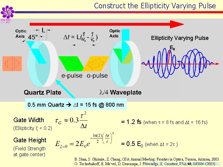
Construct the Ellipticity Varying Pulse E 0 0. 5 mm Quartz t = 15 fs @ 800 nm Gate Width = 1. 2 fs (when = 8 fs and t = 16 fs) (Ellipticity ξ < 0. 2) Gate Height (Field Strength at gate center) = 0. 5 E 0 (when t = 2 ) B. Shan, S. Ghimire, Z. Chang, OSA Annual Meeting: Frontier in Optics, Tucson, Arizona, 2003 Atomic Physics Seminar, KSU O. Techerbakoff, E. Me´vel, D. Descamps, J. 5/12/2004, Plumridge, E. Constant, PRA 68, 043804 (2003)
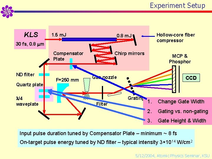
Experiment Setup KLS 1. 5 m. J Hollow-core fiber compressor 0. 8 m. J 30 fs, 0. 8 m Chirp mirrors Compensator Plate ND filter Quartz plate /4 waveplate F=250 mm MCP & Phosphor Gas nozzle CCD Grating Filter 1. Change Gate Width 2. Gating vs. non-gating 3. Gate Height & Width Input pulse duration tuned by Compensator Plate – minimum ~ 8 fs On-target pulse energy tuned by ND filter – typical intensity 3× 10¹⁴ W/cm 2 5/12/2004, Atomic Physics Seminar, KSU
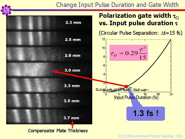
Change Input Pulse Duration and Gate Width Polarization gate width G vs. Input pulse duration (Circular Pulse Separation: t=15 fs) 1. 3 fs ! Compensator Plate Thickness 5/12/2004, Atomic Physics Seminar, KSU
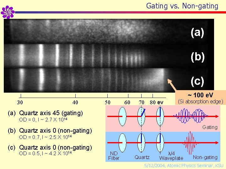
Gating vs. Non-gating (a) (b) (c) ~ 100 e. V 30 40 50 60 70 80 ev (Si absorption edge) (a) Quartz axis 45 (gating) OD = 0, I ~ 2. 7 X 10¹⁴ Gating (b) Quartz axis 0 (non-gating) OD = 0. 7, I ~ 2. 5 X 10¹⁴ (c) Quartz axis 0 (non-gating) OD = 0. 5, I ~ 4. 2 X 10¹⁴ ND Filter Quartz /4 Waveplate Non-gating 5/12/2004, Atomic Physics Seminar, KSU
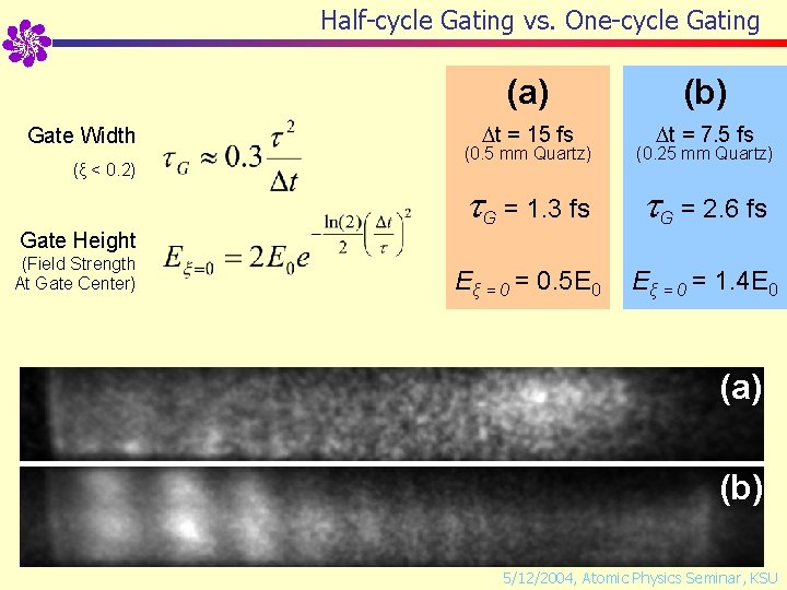
Half-cycle Gating vs. One-cycle Gating (a) Gate Width (ξ < 0. 2) t = 15 fs (b) t = 7. 5 fs (0. 5 mm Quartz) (0. 25 mm Quartz) G = 1. 3 fs G = 2. 6 fs Eξ = 0. 5 E 0 Eξ = 0 = 1. 4 E 0 Gate Height (Field Strength At Gate Center) (a) (b) 5/12/2004, Atomic Physics Seminar, KSU
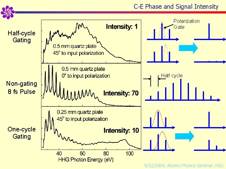
C-E Phase and Signal Intensity Half-cycle Gating Polarization Gate Half cycle Non-gating 8 fs Pulse One-cycle Gating 5/12/2004, Atomic Physics Seminar, KSU
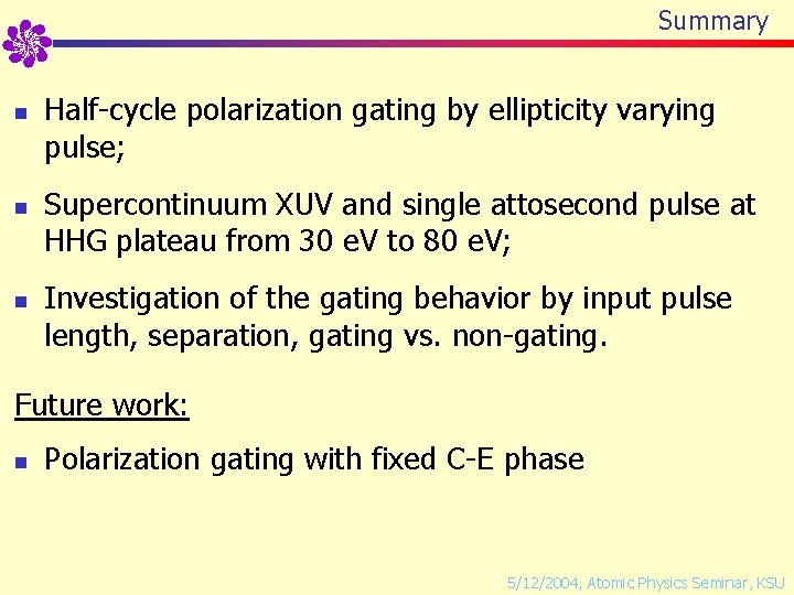
Summary n n n Half-cycle polarization gating by ellipticity varying pulse; Supercontinuum XUV and single attosecond pulse at HHG plateau from 30 e. V to 80 e. V; Investigation of the gating behavior by input pulse length, separation, gating vs. non-gating. Future work: n Polarization gating with fixed C-E phase 5/12/2004, Atomic Physics Seminar, KSU
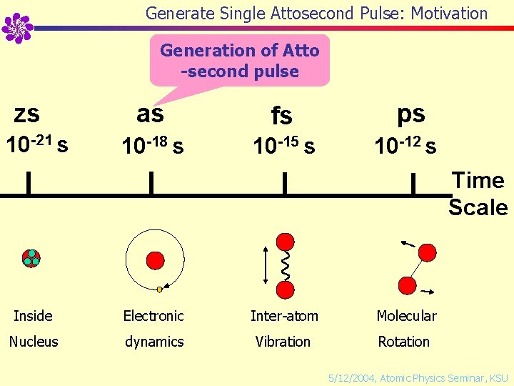
Generate Single Attosecond Pulse: Motivation Generation of Atto -second pulse zs 10 -21 s as fs ps 10 -18 s 10 -15 s 10 -12 s Time Scale Inside Electronic Inter-atom Molecular Nucleus dynamics Vibration Rotation 5/12/2004, Atomic Physics Seminar, KSU
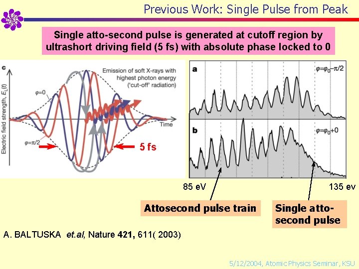
Previous Work: Single Pulse from Peak Single atto-second pulse is generated at cutoff region by ultrashort driving field (5 fs) with absolute phase locked to 0 5 fs 85 e. V 135 ev Attosecond pulse train Single attosecond pulse A. BALTUSKA et. al, Nature 421, 611( 2003) 5/12/2004, Atomic Physics Seminar, KSU
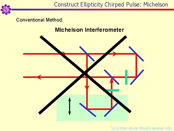
Construct Ellipticity Chirped Pulse: Michelson Conventional Method: Michelson Interferometer 5/12/2004, Atomic Physics Seminar, KSU
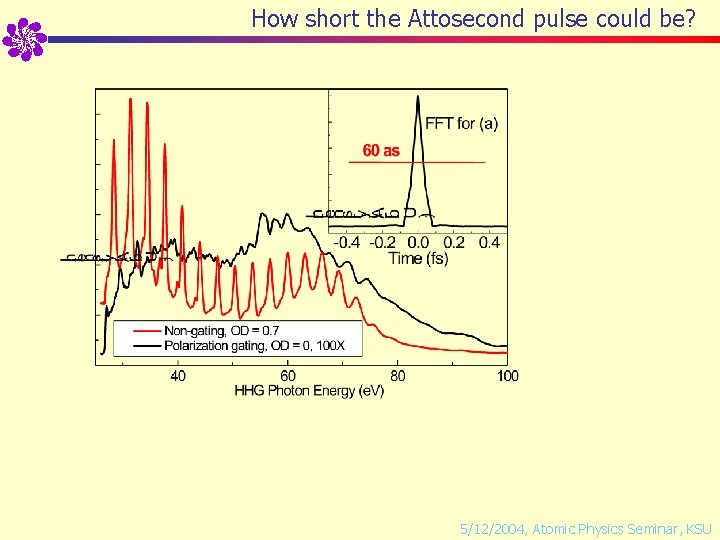
How short the Attosecond pulse could be? 5/12/2004, Atomic Physics Seminar, KSU
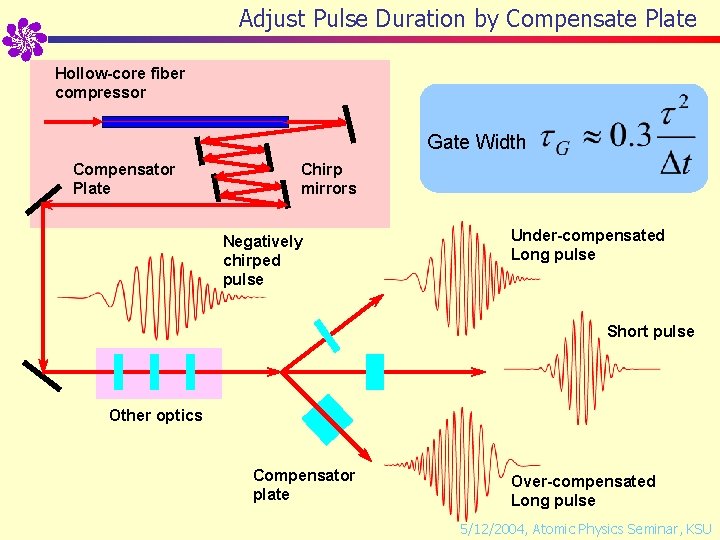
Adjust Pulse Duration by Compensate Plate Hollow-core fiber compressor Gate Width Compensator Plate Chirp mirrors Negatively chirped pulse Under-compensated Long pulse Short pulse Other optics Compensator plate Over-compensated Long pulse 5/12/2004, Atomic Physics Seminar, KSU
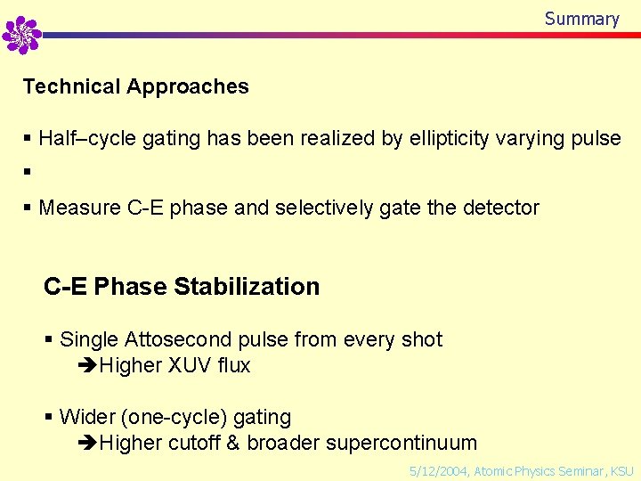
Summary Technical Approaches § Half–cycle gating has been realized by ellipticity varying pulse § § Measure C-E phase and selectively gate the detector C-E Phase Stabilization § Single Attosecond pulse from every shot Higher XUV flux § Wider (one-cycle) gating Higher cutoff & broader supercontinuum 5/12/2004, Atomic Physics Seminar, KSU
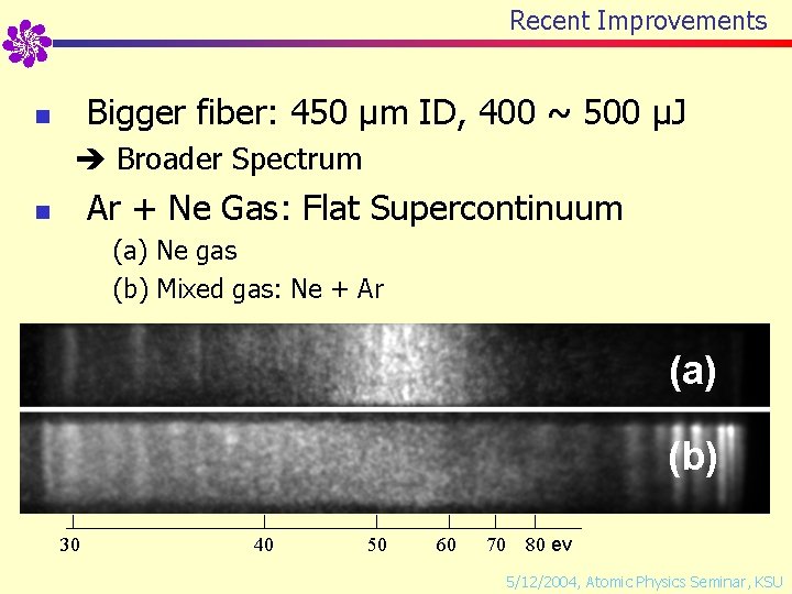
Recent Improvements Bigger fiber: 450 µm ID, 400 ~ 500 µJ n Broader Spectrum Ar + Ne Gas: Flat Supercontinuum n (a) Ne gas (b) Mixed gas: Ne + Ar (a) (b) 30 40 50 60 70 80 ev 5/12/2004, Atomic Physics Seminar, KSU
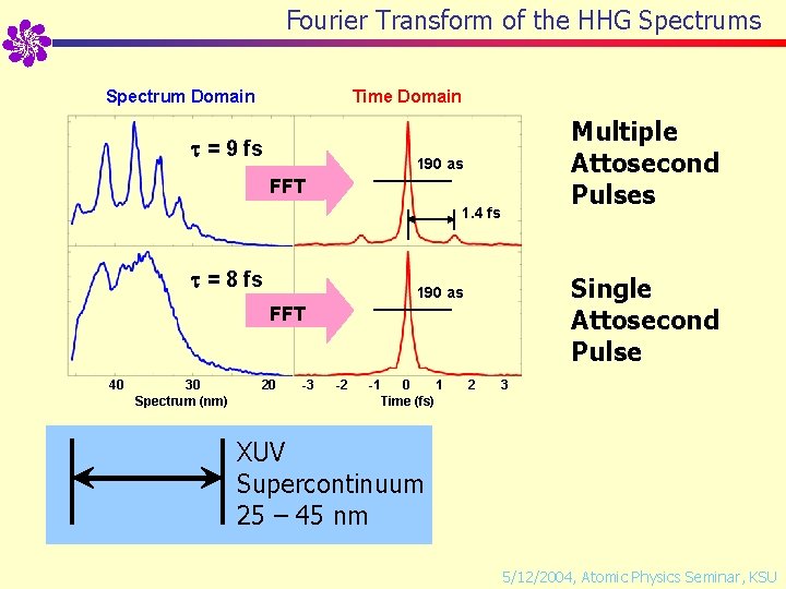
Fourier Transform of the HHG Spectrums Spectrum Domain Time Domain = 9 fs Multiple Attosecond Pulses 190 as FFT 1. 4 fs = 8 fs Single Attosecond Pulse 190 as FFT 40 30 Spectrum (nm) 20 -3 -2 -1 0 1 Time (fs) 2 3 XUV Supercontinuum 25 – 45 nm 5/12/2004, Atomic Physics Seminar, KSU
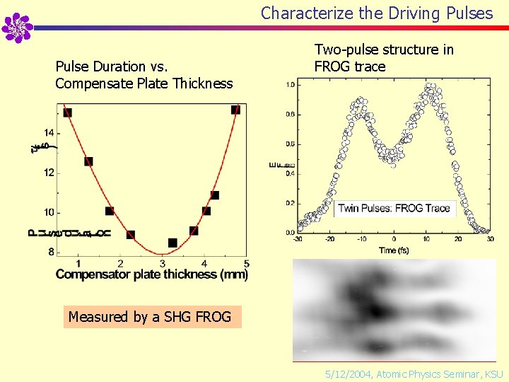
Characterize the Driving Pulses Pulse Duration vs. Compensate Plate Thickness Two-pulse structure in FROG trace Measured by a SHG FROG 5/12/2004, Atomic Physics Seminar, KSU
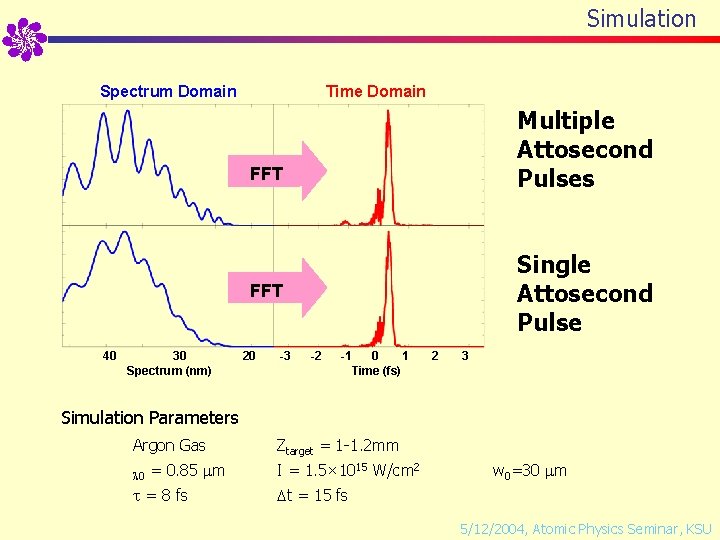
Simulation Spectrum Domain Time Domain Multiple Attosecond Pulses FFT Single Attosecond Pulse FFT 40 30 Spectrum (nm) 20 -3 -2 -1 0 1 Time (fs) 2 3 Simulation Parameters Argon Gas 0 = 0. 85 m = 8 fs Ztarget = 1 -1. 2 mm I = 1. 5× 10¹⁵ W/cm 2 w 0=30 m t = 15 fs 5/12/2004, Atomic Physics Seminar, KSU
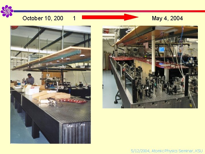
October 10, 200 1 May 4, 2004 5/12/2004, Atomic Physics Seminar, KSU