KAGRAPower Recycling III KAGRA collaboration KAGRA VIS Laser

KAGRAにおけるPower Recycling鏡の防振 懸架系システムの開発 III 正田亜八香、KAGRA collaboration

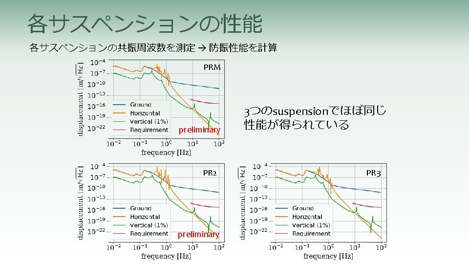
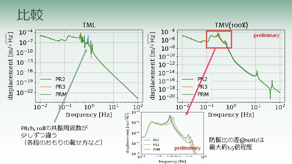
KAGRA VIS Laser in Requirements
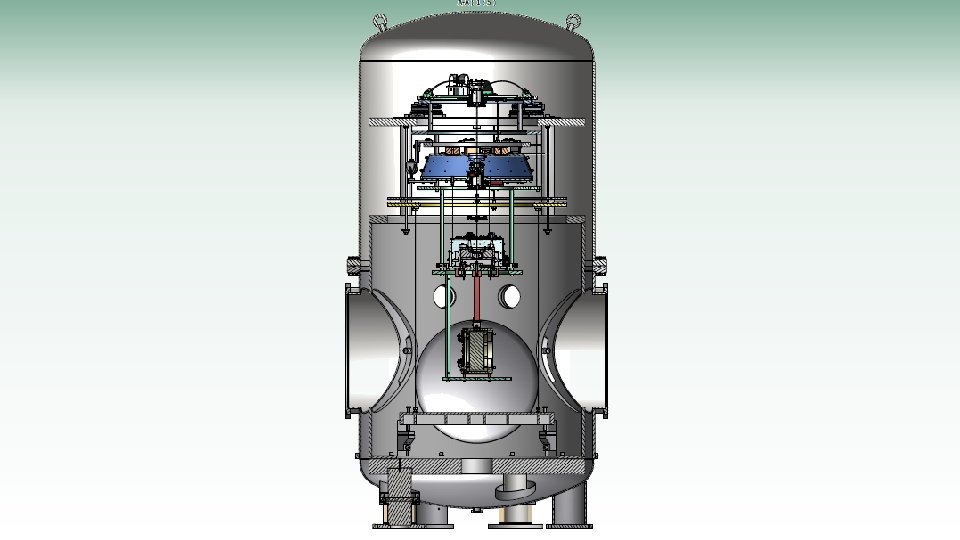
 Type-Bp Traverser 0. 6 m GAS 2 (Bottom filter) 1.")
GAS 1 (Standard filter) Type-Bp Traverser 0. 6 m GAS 2 (Bottom filter) 1. 7 m 0. 5 m Intermediate mass/ Intermediate recoil mass 0. 6 m PR mirror/ Recoil mass

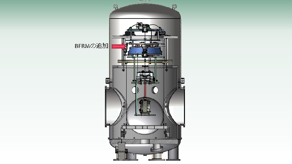
解決策 NEW! BF IM/IRM Mirror/RM

Test Hangingで得られた結果


Mirror trouble 1. OSEM flag removing took a long time The position and dimension of the flags make it difficult to dissolve the glue. In case of the spare mirror and the i. KAGRA PR 3, they were removed within a week. This time, two of the flags could not be removed more than 2 weeks. 2. Some of the wire breakers refused to be glued on the mirror for a long time We could attached the wire breakers in i. KAGRA phase (but sapphire) once with the same condition, but this time, we failed gluing many times. We do not know the reason, but they are glued when we changed the gluing jig box (dimension is the same) and with the supervise of experienced person.

Other new topics/troubles • The tilt of the mirror changed a lot after we fixed the mirror. The suspension wires around the mirror slipped? • The PR 2 mirror is thinner than design…? ? • PRM DGS system and PR 3 DGS system cannot be worked at the same time. Now we are sharing PR 3 model with PR 3 and PRM. • We found some screws to be replaced including the PR 3 (vent holes required). Optical bench • The optical bench is suspended. The performance is not yet measured. The height of the optical bench have to be changed from the original design since the spacers in PR 2 tank, which were inserted during the i. KAGRA phase, cannot be removed. Spacers are inserted here

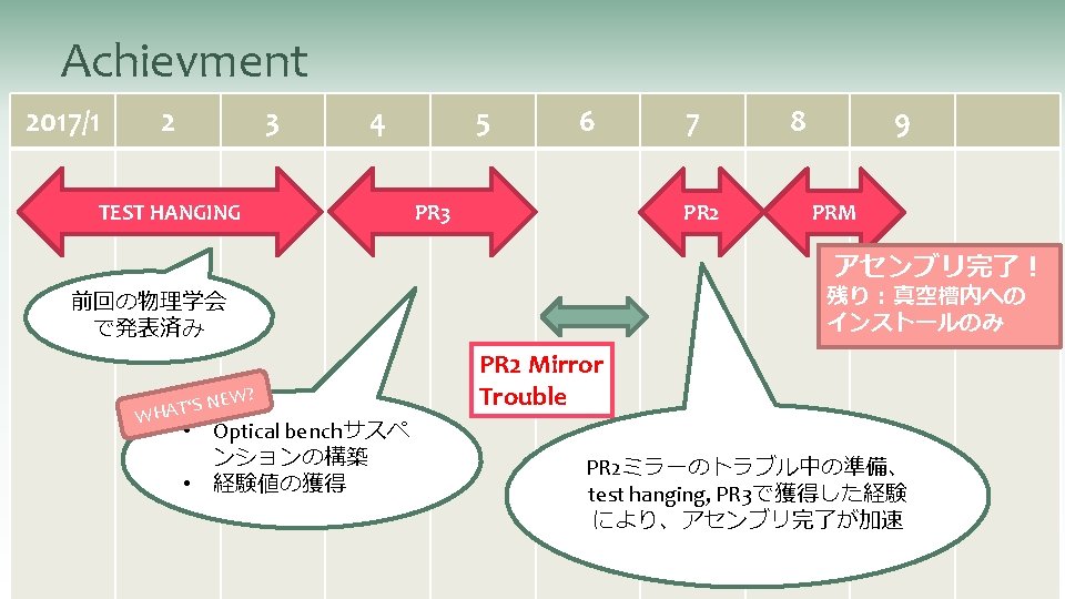
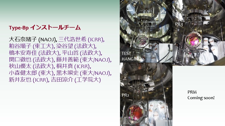
Test Hanging Purpose:Checking assembly procedure Damping performance evaluation Period: 2017/1/10 – 2017/3/15 Type-Bp installation team: Ayaka Shoda (NAOJ), Naoko Ohishi (NAOJ), Koseki Miyo (ICRR) Many thanks to the shift workers: Junko Kasuya (Titech), Nozomi Someya (Hosei), and Yasuka Hashimoto (Hosei)!!

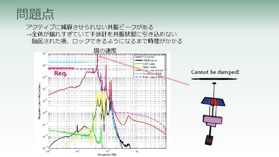
Problem One of the resonance mode cannot be damped properly. →Unable to lock the interferometer since the velocity is too large. Decrease the duty cycle after the large perturbation such as earthquakes. Velocity of the mirror Req. Cannot be damped!

How to solve NEW! BF IM/IRM Mirror/RM

Model Sensor & actuator Inspired from Filter 7 damping system in Virgo. Thanks to R. Passaquieti, V. Dattilo, and F. Paoletti. BFRM ring

New from i. KAGRA • BF damping system BF recoil mass BF LVDT (sensors and actuators) • 3 stage pendulum+2 GAS filters • Wide cavity OSEMs • Remove sensing function on the TM OSEMS Length-sensing Op. Lev • Design change in the IM OSEM flags • Changing disassembly procedure IM OSEM TM OSEM

Measurement Active damping using the local sensors and actuator at each stage. LVDT for GAS (sensor & actuator unit) * ground-suspension point 6 LVDTs * BF-BFRM 1 LVDT for GAS * BF-suspension point 6 OSEMs (sensor & actuator unit) * IM-IRM 4 coil-magnet actuators Angular optical lever (Op. Lev) Length sensing optical lever * ground-mirror

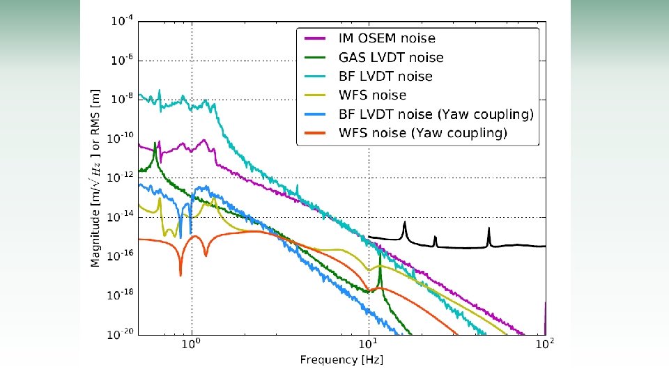
Results BF LVDT * Calibration factors have large uncertainty for BF LVDT. V Y R P L T w/o damping IM OSEM GAS LVDT

Results BF LVDT * Calibration factors have large uncertainty for BF LVDT. V Y R P L T w/ damping IM OSEM GAS LVDT

w/o Damping Result * Calibration factors have large uncertainty. w/o Damping Mirror YAW w/ IM Damping Mirror Displacement w/ IM Damping w/ IM& BF Damping w/o Damping Mirror PITCH w/ IM Damping w/ IM& BF Damping

Result * Calibration factors have large uncertainty. Mirror Velocity w/o Damping w/ IM Damping Req. Limited by sensor noise w/ IM& BF Damping Resonant mode is properly damped

Compare with the simulation Req. 28

Schedule One month delay from the first plan. How to speed up? • Lost 2 weeks since gluing tools are missing. The handover was not proper. This should not happen again. (We did almost everything during the test hanging. ) • Lost 1 week because the mirror hanging was failed once (not a big accident). This kind of accident can be happen again. We have to take them into account in our schedule. • Lost 1 week because of fixing the fragile cables again and again. Cabling work was a lot more time consuming than expected. We will outsource this work to a company.

Tasks remained • Improve the efficiency of the time consuming work Improve the safety (ex. outsourcing the cable assembly, prepare more steps on the 2 nd floor) • Calibrate each sensors & actuators • Optimize the control loop Decrease noise coupling • De-coupling of the length-sensing Op. Lev • Measurement of Q-values • Optical bench suspension

Future plan 2017 April-May Other shift workers from Hosei Univ. will join!! PR 3 mirror is ready to be shipped to Kamioka on 3 rd April. 2017 May-June 2017 June-July

Summary • Upgrade Type-Bp suspension from i. KAGRA All the resonant modes are damped • Test Hanging is done Checked the damping • PR 3 mirror suspension will be assembled from April. PR installation will be completed in this summer.

i. KAGRA b. KAGRA
 DGS trouble EQ stop assembling IM")
Gluing Winch inspection Mirror hanging (2 nd try) DGS trouble EQ stop assembling IM hanging IRM assembly Gluing Mirror alignment Mirror hanging RM alignment Spectra Parts inspection measurement TF measurement OSEM flag BF preparation BF setting assembly

IM TF measurement BFRM test assembly @Mitaka Set IM damping Picomotor check LVDT calibration BFRM assembled OB suspension parts checked Parts preparation BF assembly OB suspension parts checked Top plate SF assembly Cabling BFRM test assembly @Mitaka BF hanging Ballast mass setting Cabling BF balancing BFRM coil assembly Signal check IM OSEM alignment BF balancing

Signal check Installation preparation Installation Cabling Oplev setting Measurement Remove SUS from chamber BF signal check Signal check Disassembly Signal check Chamber moving Calibration

RM hanging RM alignment EQ stop assembling Spectra measurement TF measurement IM hanging BF preparation. BF setting IRM assembly IM TF measurement Mirror hanging Mirror alignment Set IM damping LVDT calibration BFRM assembled Top plate SF assembly Picomotor check BF assembly BF hanging Ballast mass setting Signal check Installation preparation Cabling Installation BF balancing Cabling BF balancing BFRM coil assembly

V Damping time simulation ※controlled only in L, T, Y at BF TM T, RM -T L mirror (optical axis) BR V 39 T
- Slides: 39