
Joe Pellicciotti joseph w pellicciottinasa gov An Overview


- Slides: 62
Joe Pellicciotti joseph. w. pellicciotti@nasa. gov An Overview of Fastener Requirements in the new NASA-STD-5020 Learning from the Past, Looking to the Future Page: 1
SLa. MS Webcast Series Learning from the Past, Looking to the Future
An Overview of the New NASA-STD-5020 Requirements for Threaded Fastening Systems in Spaceflight Hardware Rob Wingate, NASA Marshall Space Flight Center rob. wingate@nasa. gov April 26, 2012
Introduction to NASA-STD-5020 Acknowledgements Thanks to Tom Sarafin (Instar Engineering and Consulting, Inc. ), who helped prepare the original charts upon which this presentation is based Thanks to Andy Hissam (MSFC) for providing torque-tension data Thanks to Dan Mc. Guinness (GSFC) for use of charts he prepared for FEMCI 4
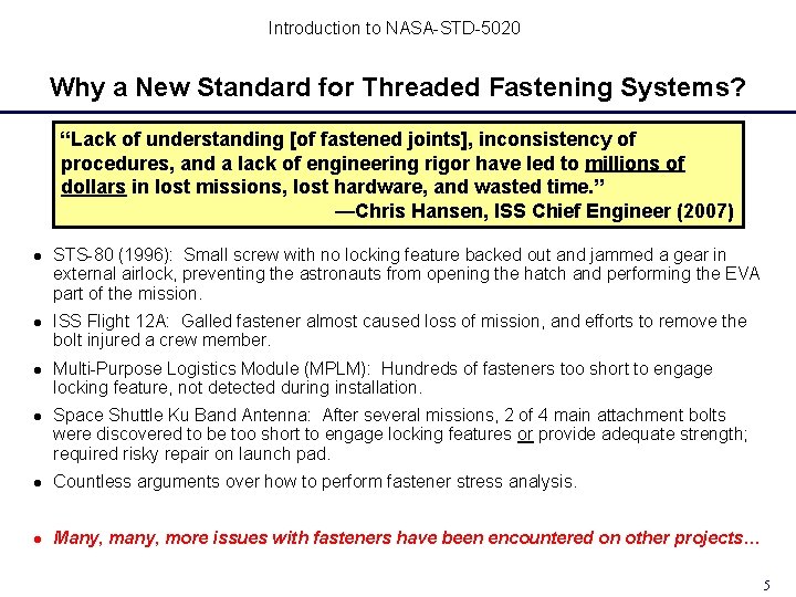
Introduction to NASA-STD-5020 Why a New Standard for Threaded Fastening Systems? “Lack of understanding [of fastened joints], inconsistency of procedures, and a lack of engineering rigor have led to millions of dollars in lost missions, lost hardware, and wasted time. ” —Chris Hansen, ISS Chief Engineer (2007) STS-80 (1996): Small screw with no locking feature backed out and jammed a gear in external airlock, preventing the astronauts from opening the hatch and performing the EVA part of the mission. ISS Flight 12 A: Galled fastener almost caused loss of mission, and efforts to remove the bolt injured a crew member. Multi-Purpose Logistics Module (MPLM): Hundreds of fasteners too short to engage locking feature, not detected during installation. Space Shuttle Ku Band Antenna: After several missions, 2 of 4 main attachment bolts were discovered to be too short to engage locking features or provide adequate strength; required risky repair on launch pad. Countless arguments over how to perform fastener stress analysis. Many, more issues with fasteners have been encountered on other projects… 5
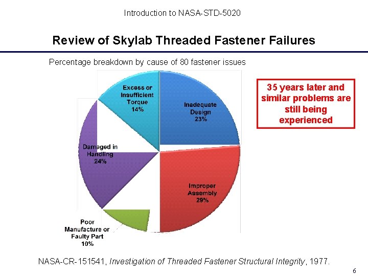
Introduction to NASA-STD-5020 Review of Skylab Threaded Fastener Failures Percentage breakdown by cause of 80 fastener issues 35 years later and similar problems are still being experienced NASA-CR-151541, Investigation of Threaded Fastener Structural Integrity, 1977. 6
Introduction to NASA-STD-5020 More Reasons for the New Standard As of December 9, 2011, NSTS 08307 A, Space Shuttle Criteria for Preloaded Bolts is “retired, ” with status now listed as “withdrawn” on the NASA Standards web site NASA-STD-5020 is intended to replace NSTS 08307 as the standard for threaded fastening system analysis on all NASA projects – Includes significant changes in analysis methodology – Supporting justification provided in appendices And goes beyond NSTS 08307 by addressing … – design considerations such as locking features, design preac, and material selection – verification and quality assurance – responsibilities of the hardware developer Be aware that some projects are still under contract to use NSTS 08307 even though it is no longer active 7
Introduction to NASA-STD-5020 The Threaded Fastening System Standard Development Sponsored by the NESC through the Mechanical Systems Technical Discipline Team 4 -year development effort started in 2007 Multi-organization development team – Multi-NASA center – Industry participation – Academia participation Supported by test and analysis efforts Multiple iterations to achieve final content Extensive technical review 8
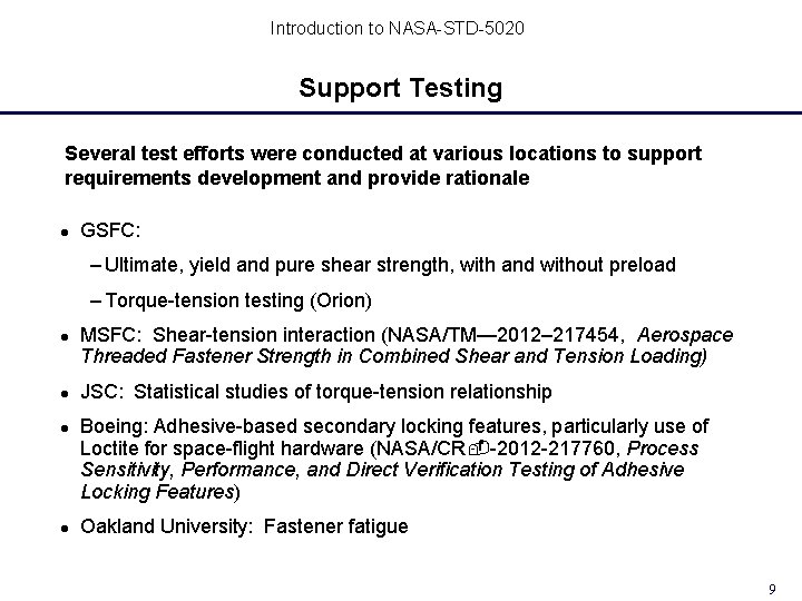
Introduction to NASA-STD-5020 Support Testing Several test efforts were conducted at various locations to support requirements development and provide rationale GSFC: – Ultimate, yield and pure shear strength, with and without preload – Torque-tension testing (Orion) MSFC: Shear-tension interaction (NASA/TM— 2012– 217454, Aerospace Threaded Fastener Strength in Combined Shear and Tension Loading) JSC: Statistical studies of torque-tension relationship Boeing: Adhesive-based secondary locking features, particularly use of Loctite for space-flight hardware (NASA/CR -2012 -217760, Process Sensitivity, Performance, and Direct Verification Testing of Adhesive Locking Features) Oakland University: Fastener fatigue 9
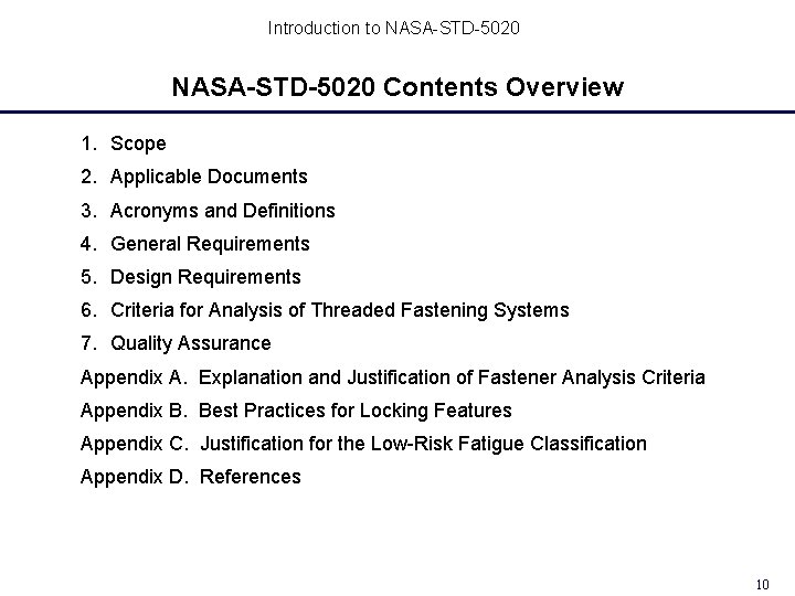
Introduction to NASA-STD-5020 Contents Overview 1. Scope 2. Applicable Documents 3. Acronyms and Definitions 4. General Requirements 5. Design Requirements 6. Criteria for Analysis of Threaded Fastening Systems 7. Quality Assurance Appendix A. Explanation and Justification of Fastener Analysis Criteria Appendix B. Best Practices for Locking Features Appendix C. Justification for the Low-Risk Fatigue Classification Appendix D. References 10
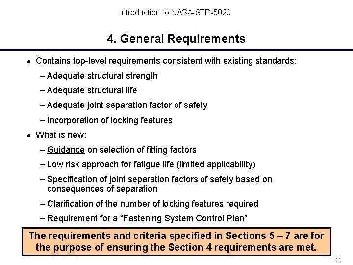
Introduction to NASA-STD-5020 4. General Requirements Contains top-level requirements consistent with existing standards: – Adequate structural strength – Adequate structural life – Adequate joint separation factor of safety – Incorporation of locking features What is new: – Guidance on selection of fitting factors – Low risk approach for fatigue life (limited applicability) – Specification of joint separation factors of safety based on consequences of separation – Clarification of the number of locking features required – Requirement for a “Fastening System Control Plan” The requirements and criteria specified in Sections 5 – 7 are for the purpose of ensuring the Section 4 requirements are met. 11
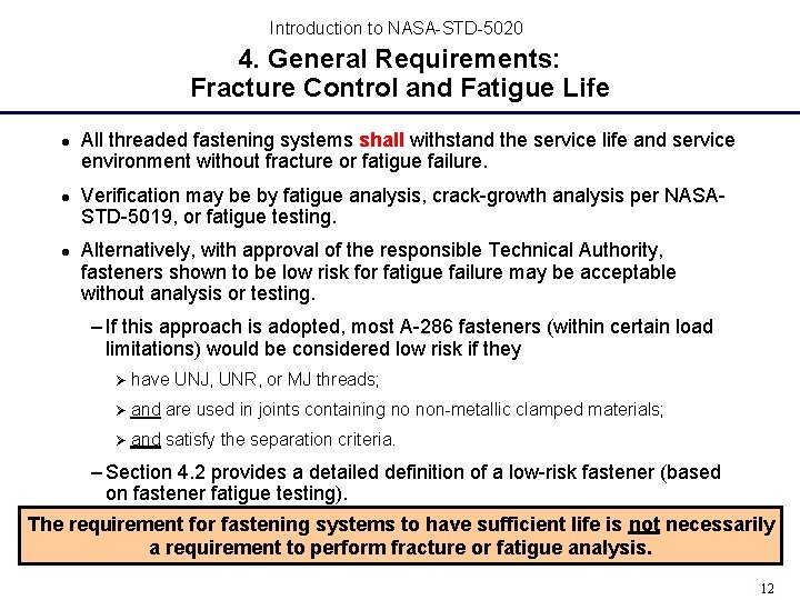
Introduction to NASA-STD-5020 4. General Requirements: Fracture Control and Fatigue Life All threaded fastening systems shall withstand the service life and service environment without fracture or fatigue failure. Verification may be by fatigue analysis, crack-growth analysis per NASASTD-5019, or fatigue testing. Alternatively, with approval of the responsible Technical Authority, fasteners shown to be low risk for fatigue failure may be acceptable without analysis or testing. – If this approach is adopted, most A-286 fasteners (within certain load limitations) would be considered low risk if they Ø have UNJ, UNR, or MJ threads; Ø and are used in joints containing no non-metallic clamped materials; Ø and satisfy the separation criteria. – Section 4. 2 provides a detailed definition of a low-risk fastener (based on fastener fatigue testing). The requirement for fastening systems to have sufficient life is not necessarily a requirement to perform fracture or fatigue analysis. 12
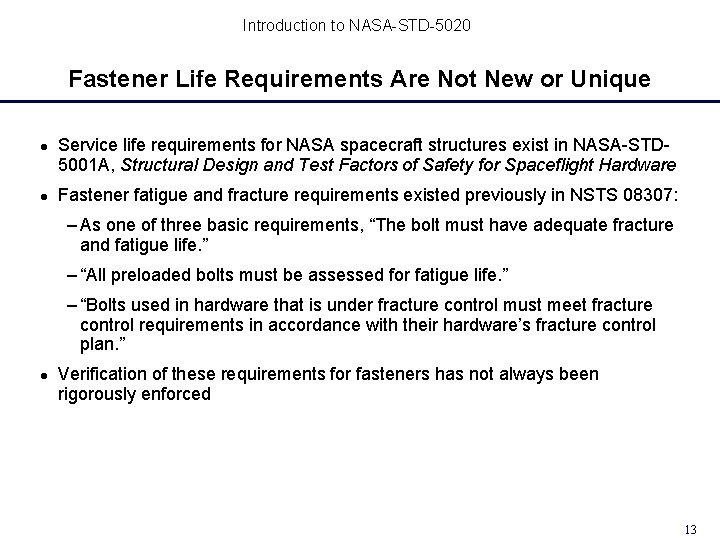
Introduction to NASA-STD-5020 Fastener Life Requirements Are Not New or Unique Service life requirements for NASA spacecraft structures exist in NASA-STD 5001 A, Structural Design and Test Factors of Safety for Spaceflight Hardware Fastener fatigue and fracture requirements existed previously in NSTS 08307: – As one of three basic requirements, “The bolt must have adequate fracture and fatigue life. ” – “All preloaded bolts must be assessed for fatigue life. ” – “Bolts used in hardware that is under fracture control must meet fracture control requirements in accordance with their hardware’s fracture control plan. ” Verification of these requirements for fasteners has not always been rigorously enforced 13
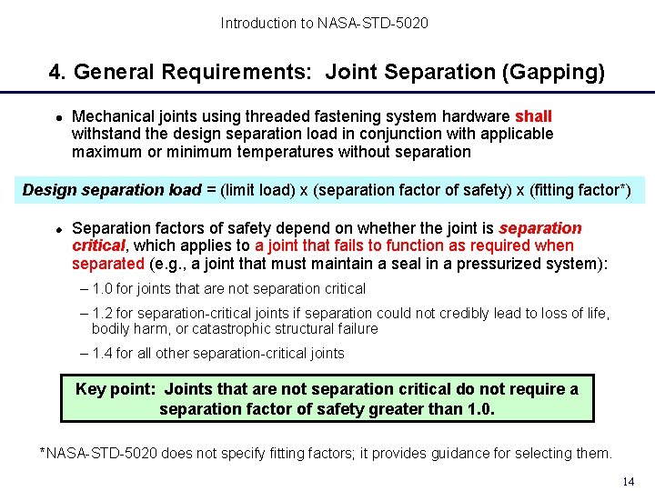
Introduction to NASA-STD-5020 4. General Requirements: Joint Separation (Gapping) Mechanical joints using threaded fastening system hardware shall withstand the design separation load in conjunction with applicable maximum or minimum temperatures without separation Design separation load = (limit load) x (separation factor of safety) x (fitting factor*) Separation factors of safety depend on whether the joint is separation critical, which applies to a joint that fails to function as required when separated (e. g. , a joint that must maintain a seal in a pressurized system): – 1. 0 for joints that are not separation critical – 1. 2 for separation-critical joints if separation could not credibly lead to loss of life, bodily harm, or catastrophic structural failure – 1. 4 for all other separation-critical joints Key point: Joints that are not separation critical do not require a separation factor of safety greater than 1. 0. *NASA-STD-5020 does not specify fitting factors; it provides guidance for selecting them. 14
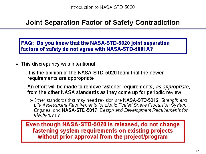
Introduction to NASA-STD-5020 Joint Separation Factor of Safety Contradiction FAQ: Do you know that the NASA-STD-5020 joint separation factors of safety do not agree with NASA-STD-5001 A? This discrepancy was intentional – It is the opinion of the NASA-STD-5020 team that the newer requirements are appropriate – An effort will be made to remove fastener requirements, as appropriate, from the other NASA standards as they come up for periodic review Ø Other standards that may need revision are NASA-STD-5012, Strength and Life Assessment Requirements for Liquid Fueled Space Propulsion System Engines, and NASA-STD-5017, Design and Development Requirements for Mechanisms Even though NASA-STD-5020 is released, do not change fastening system requirements on existing projects without prior approval from the project/program 15
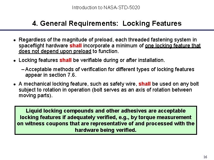
Introduction to NASA-STD-5020 4. General Requirements: Locking Features Regardless of the magnitude of preload, each threaded fastening system in spaceflight hardware shall incorporate a minimum of one locking feature that does not depend upon preload to function. Locking features shall be verifiable during or after installation. – Acceptable methods of verification for different types of locking features appear in section 7. 6. A mechanical locking feature, such as safety wire, shall be used on any bolt subject to rotation in operation (bolt serves as an axis of rotation between moving parts). Liquid locking compounds and other adhesives are acceptable locking features if adequately verified, e. g. , by torque measurement on witness coupons that are representative of and processed with the hardware being verified. 16
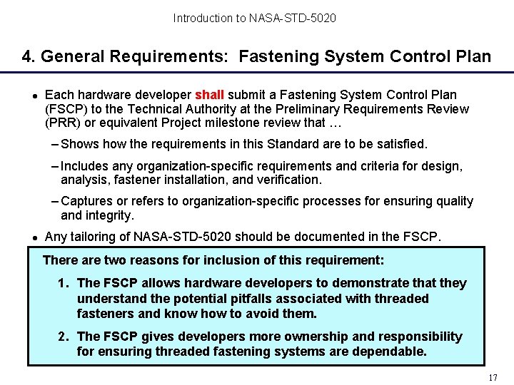
Introduction to NASA-STD-5020 4. General Requirements: Fastening System Control Plan Each hardware developer shall submit a Fastening System Control Plan (FSCP) to the Technical Authority at the Preliminary Requirements Review (PRR) or equivalent Project milestone review that … – Shows how the requirements in this Standard are to be satisfied. – Includes any organization-specific requirements and criteria for design, analysis, fastener installation, and verification. – Captures or refers to organization-specific processes for ensuring quality and integrity. Any tailoring of NASA-STD-5020 should be documented in the FSCP. There are two reasons for inclusion of this requirement: 1. The FSCP allows hardware developers to demonstrate that they understand the potential pitfalls associated with threaded fasteners and know how to avoid them. 2. The FSCP gives developers more ownership and responsibility for ensuring threaded fastening systems are dependable. 17
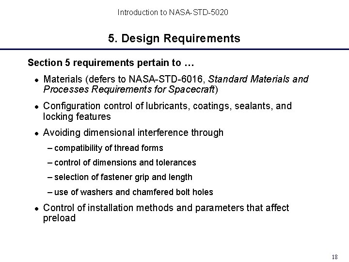
Introduction to NASA-STD-5020 5. Design Requirements Section 5 requirements pertain to … Materials (defers to NASA-STD-6016, Standard Materials and Processes Requirements for Spacecraft) Configuration control of lubricants, coatings, sealants, and locking features Avoiding dimensional interference through – compatibility of thread forms – control of dimensions and tolerances – selection of fastener grip and length – use of washers and chamfered bolt holes Control of installation methods and parameters that affect preload 18
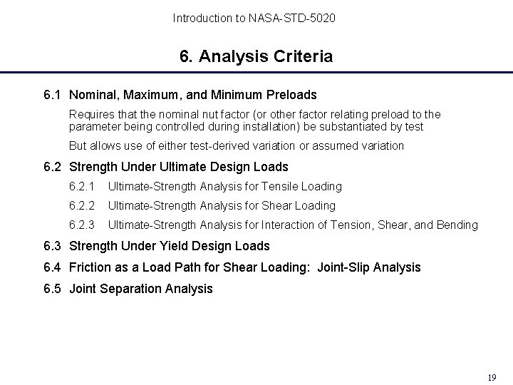
Introduction to NASA-STD-5020 6. Analysis Criteria 6. 1 Nominal, Maximum, and Minimum Preloads Requires that the nominal nut factor (or other factor relating preload to the parameter being controlled during installation) be substantiated by test But allows use of either test-derived variation or assumed variation 6. 2 Strength Under Ultimate Design Loads 6. 2. 1 Ultimate-Strength Analysis for Tensile Loading 6. 2. 2 Ultimate-Strength Analysis for Shear Loading 6. 2. 3 Ultimate-Strength Analysis for Interaction of Tension, Shear, and Bending 6. 3 Strength Under Yield Design Loads 6. 4 Friction as a Load Path for Shear Loading: Joint-Slip Analysis 6. 5 Joint Separation Analysis 19
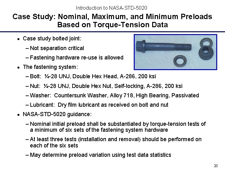
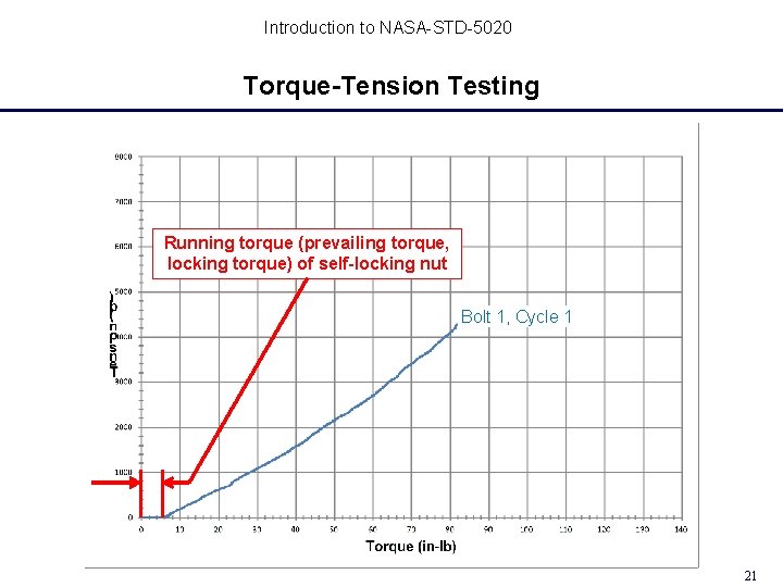
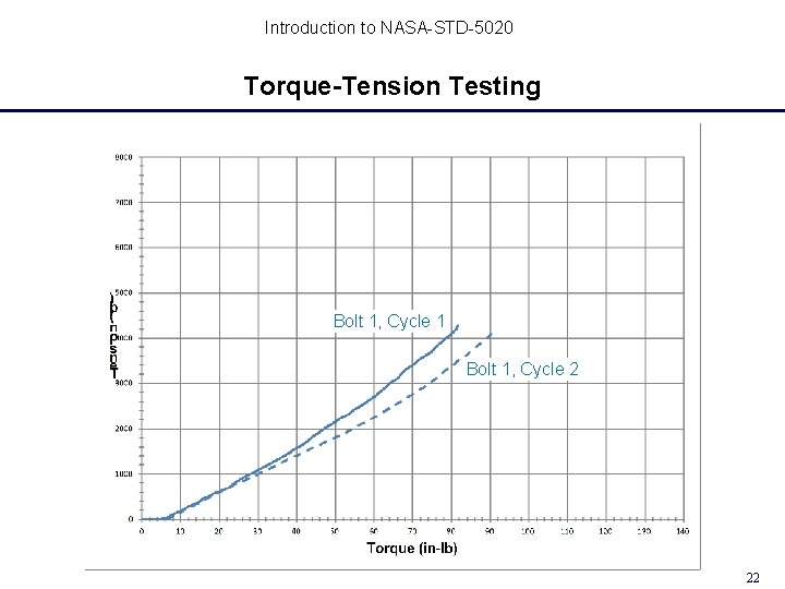
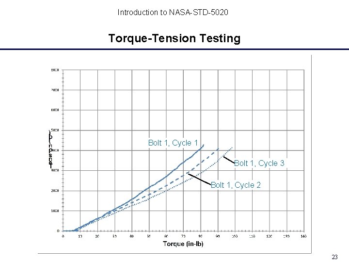
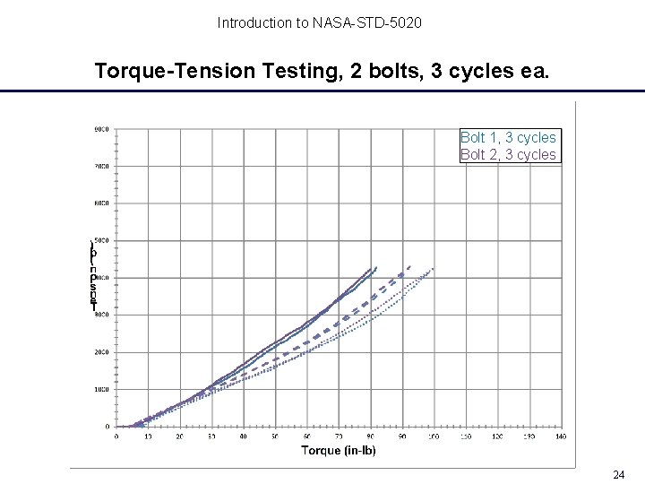
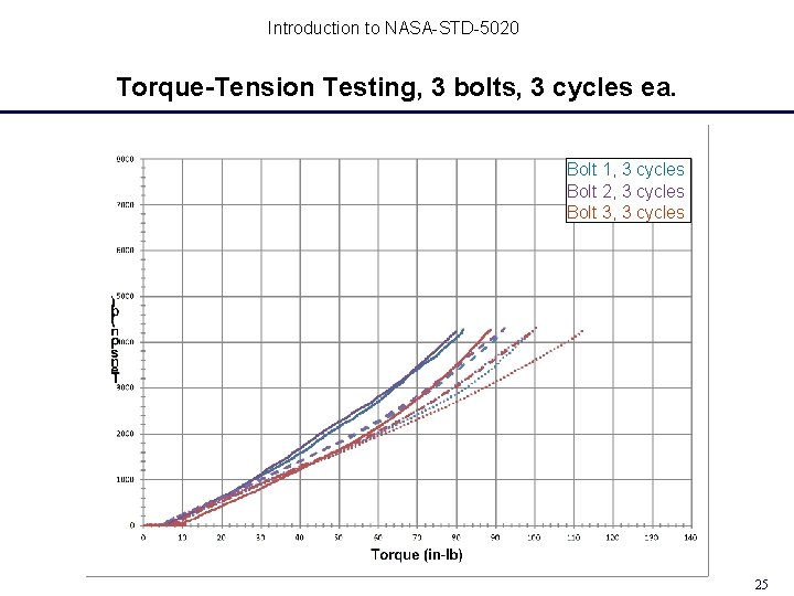
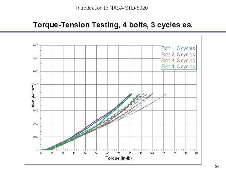
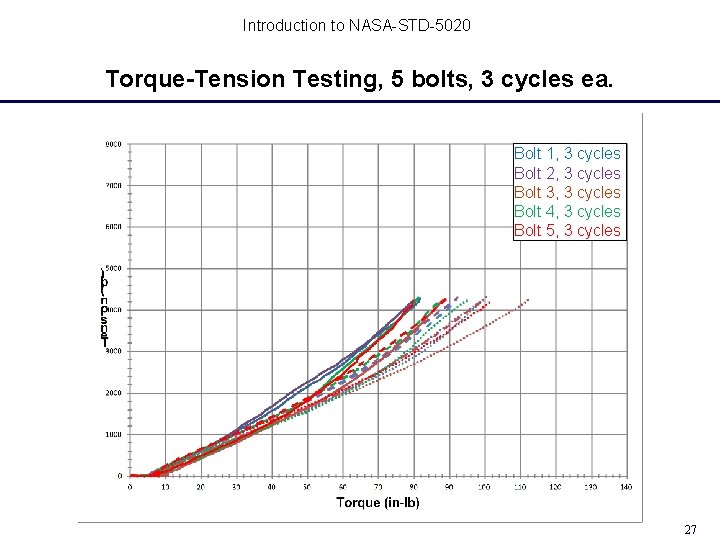
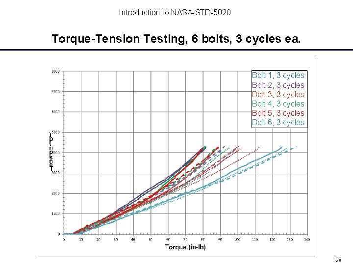
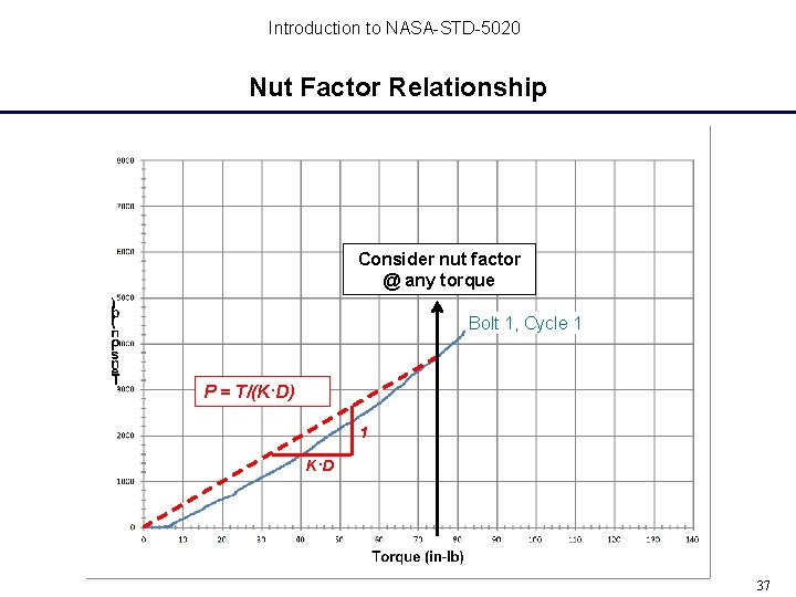
Introduction to NASA-STD-5020 Case Study: Nominal, Maximum, and Minimum Preloads Based on Torque-Tension Data Case study bolted joint: – Not separation critical – Fastening hardware re-use is allowed The fastening system: – Bolt: ¼-28 UNJ, Double Hex Head, A-286, 200 ksi – Nut: ¼-28 UNJ, Double Hex Nut, Self-locking, A-286, 200 ksi – Washer: Countersunk Washer, Alloy 718, High Bearing, Passivated – Lubricant: Dry film lubricant as received on bolt and nut NASA-STD-5020 guidance: – Nominal initial preload shall be substantiated by torque-tension tests of a minimum of six sets of the fastening system hardware – At least three tests (installation and removal) should be performed on each of the six sets – May determine preload variation using test data statistics 20
Introduction to NASA-STD-5020 Torque-Tension Testing Running torque (prevailing torque, locking torque) of self-locking nut Bolt 1, Cycle 1 21
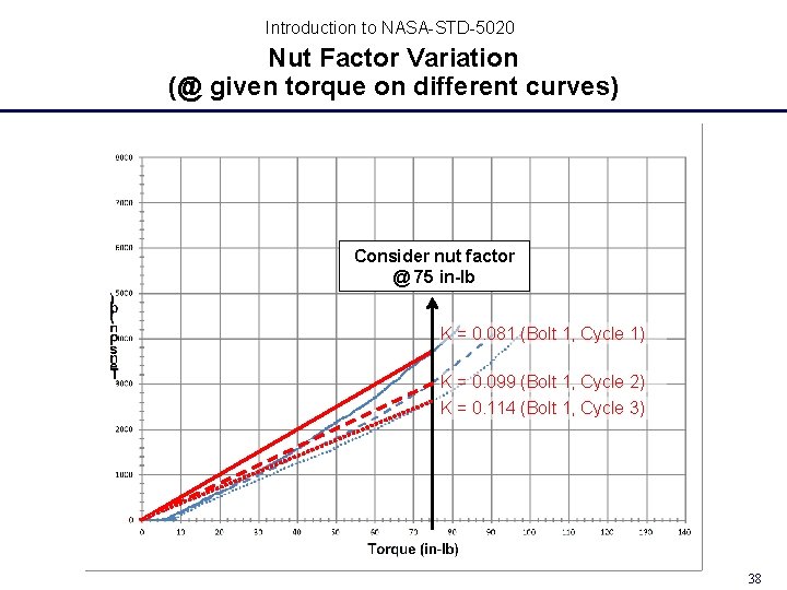
Introduction to NASA-STD-5020 Torque-Tension Testing Bolt 1, Cycle 1 Bolt 1, Cycle 2 22
Introduction to NASA-STD-5020 Torque-Tension Testing Bolt 1, Cycle 1 Bolt 1, Cycle 3 Bolt 1, Cycle 2 23
Introduction to NASA-STD-5020 Torque-Tension Testing, 2 bolts, 3 cycles ea. Bolt 1, 3 cycles Bolt 2, 3 cycles 24
Introduction to NASA-STD-5020 Torque-Tension Testing, 3 bolts, 3 cycles ea. Bolt 1, 3 cycles Bolt 2, 3 cycles Bolt 3, 3 cycles 25
Introduction to NASA-STD-5020 Torque-Tension Testing, 4 bolts, 3 cycles ea. Bolt 1, 3 cycles Bolt 2, 3 cycles Bolt 3, 3 cycles Bolt 4, 3 cycles 26
Introduction to NASA-STD-5020 Torque-Tension Testing, 5 bolts, 3 cycles ea. Bolt 1, 3 cycles Bolt 2, 3 cycles Bolt 3, 3 cycles Bolt 4, 3 cycles Bolt 5, 3 cycles 27
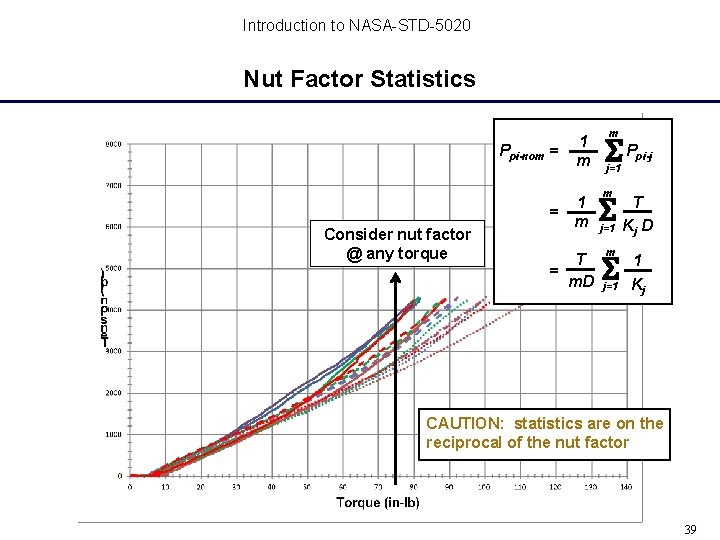
Introduction to NASA-STD-5020 Torque-Tension Testing, 6 bolts, 3 cycles ea. Bolt 1, 3 cycles Bolt 2, 3 cycles Bolt 3, 3 cycles Bolt 4, 3 cycles Bolt 5, 3 cycles Bolt 6, 3 cycles 28
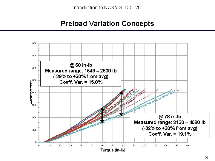
Introduction to NASA-STD-5020 Preload Variation Concepts @ 60 in-lb Measured range: 1543 – 2800 lb (-29% to +30% from avg) Coeff. Var. = 15. 8% @ 78 in-lb Measured range: 2130 – 4080 lb (-32% to +30% from avg) Coeff. Var. = 19. 1% 29
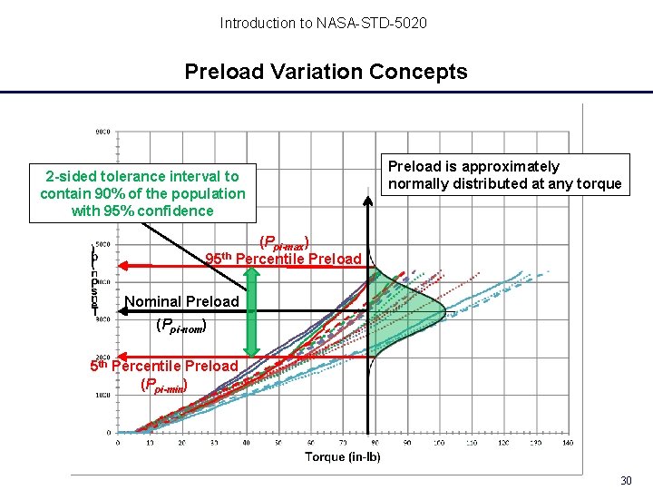
Introduction to NASA-STD-5020 Preload Variation Concepts 2 -sided tolerance interval to contain 90% of the population with 95% confidence Preload is approximately normally distributed at any torque (Ppi-max) 95 th Percentile Preload Nominal Preload (Ppi-nom) 5 th Percentile Preload (Ppi-min) 30
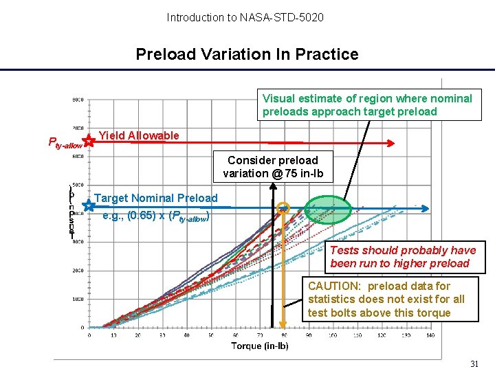
Introduction to NASA-STD-5020 Preload Variation In Practice Visual estimate of region where nominal preloads approach target preload Pty-allow Yield Allowable Consider preload variation @ 75 in-lb Target Nominal Preload e. g. , (0. 65) x (Pty-allow) Tests should probably have been run to higher preload CAUTION: preload data for statistics does not exist for all test bolts above this torque 31
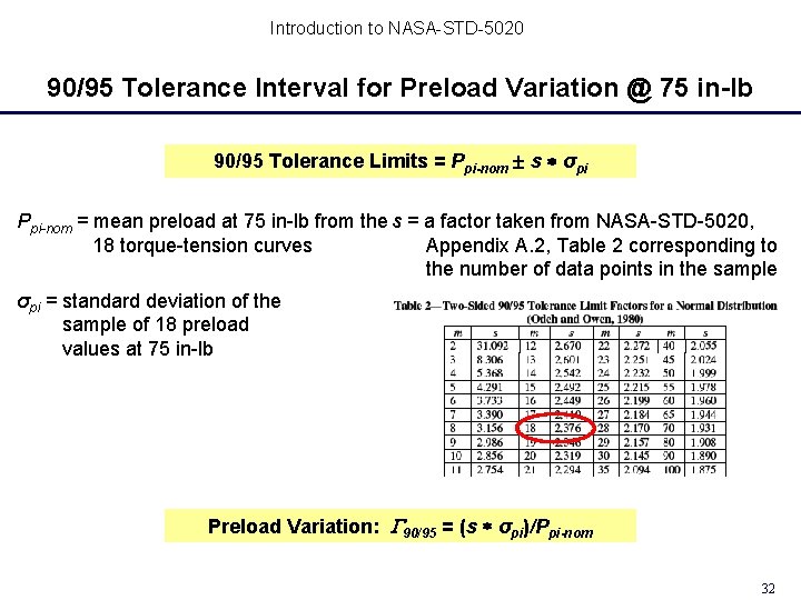
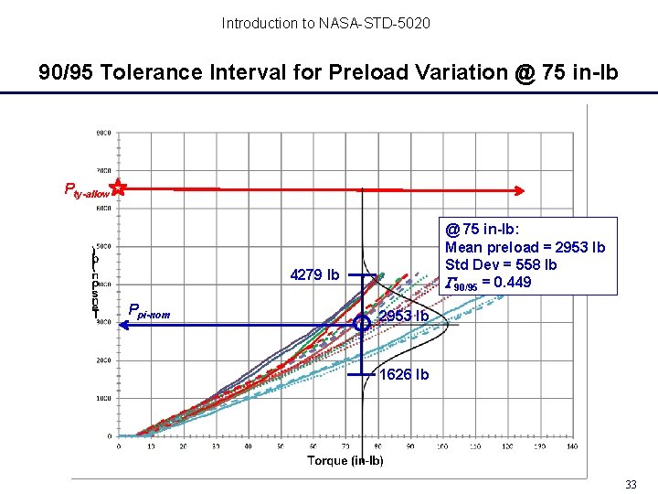
Introduction to NASA-STD-5020 90/95 Tolerance Interval for Preload Variation @ 75 in-lb 90/95 Tolerance Limits = Ppi-nom s σpi Ppi-nom = mean preload at 75 in-lb from the s = a factor taken from NASA-STD-5020, Appendix A. 2, Table 2 corresponding to 18 torque-tension curves the number of data points in the sample σpi = standard deviation of the sample of 18 preload values at 75 in-lb Preload Variation: 90/95 = (s σpi)/Ppi-nom 32
Introduction to NASA-STD-5020 90/95 Tolerance Interval for Preload Variation @ 75 in-lb Pty-allow @ 75 in-lb: Mean preload = 2953 lb Std Dev = 558 lb 90/95 = 0. 449 4279 lb Ppi-nom 2953 lb 1626 lb 33
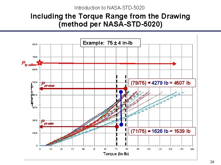
Introduction to NASA-STD-5020 Including the Torque Range from the Drawing (method per NASA-STD-5020) Example: 75 4 in-lb Pty-allow Ppi-max (79/75) 4279 lb = 4507 lb Ppi-min (71/75) 1626 lb = 1539 lb 34
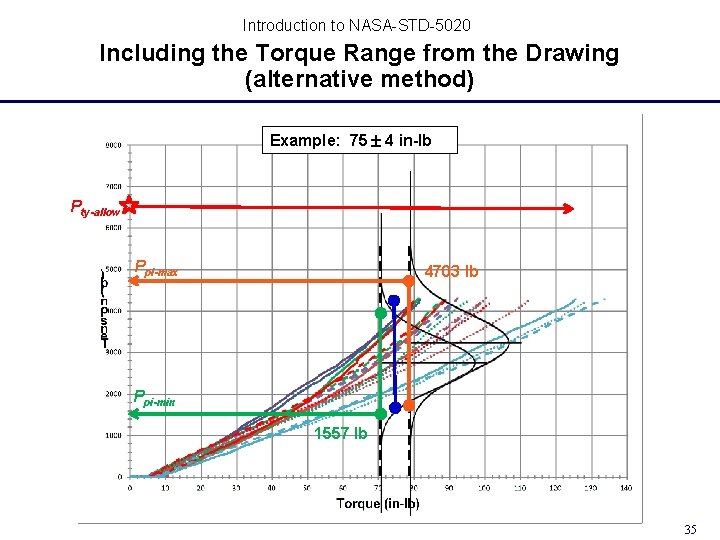
Introduction to NASA-STD-5020 Including the Torque Range from the Drawing (alternative method) Example: 75 4 in-lb Pty-allow Ppi-max 4703 lb Ppi-min 1557 lb 35
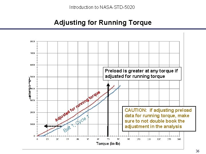
Introduction to NASA-STD-5020 Adjusting for Running Torque Preload is greater at any torque if adjusted for running torque g d ste r fo ju Ad B 1 olt , nin n u r cle y C 1 e qu r to CAUTION: if adjusting preload data for running torque, make sure to not double book the adjustment in the analysis 36
Introduction to NASA-STD-5020 Nut Factor Relationship Consider nut factor @ any torque Bolt 1, Cycle 1 P = T/(K·D) 1 K·D 37
Introduction to NASA-STD-5020 Nut Factor Variation (@ given torque on different curves) Consider nut factor @ 75 in-lb K = 0. 081 (Bolt 1, Cycle 1) K = 0. 099 (Bolt 1, Cycle 2) K = 0. 114 (Bolt 1, Cycle 3) 38
Introduction to NASA-STD-5020 Nut Factor Statistics Ppi-nom = Consider nut factor @ any torque 1 m 1 = m T = m. D m ΣP j=1 m Σ j=1 pi-j T Kj D 1 Kj CAUTION: statistics are on the reciprocal of the nut factor 39
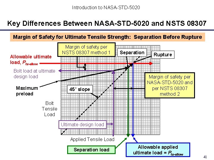
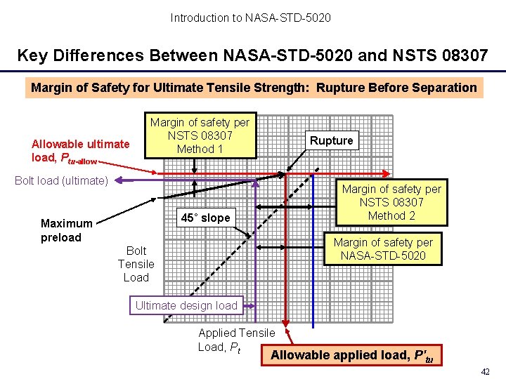
Introduction to NASA-STD-5020 Analysis Criteria Continued Key Differences Between NASA-STD-5020 and NSTS 08307 Ultimate strength analysis, tension NSTS 08307 Requires calculation of a margin of safety (MS) two ways, one based on total bolt load when including preload and one based solely on applied load. The lower MS applies. MS calculated by comparing the predicted fastener load to the allowable fastener load. NASA-STD-5020 Requires determination of whether rupture can occur before separation and calculation of the MS accordingly: • Rupture before separation: Account for preload • Separation before rupture: Ignore preload MS calculated in a way that indicates how much the applied load can increase before the criteria are not satisfied. Purpose: Encourage better understanding of the joint behavior; simplify and make the MS more meaningful. 40
Introduction to NASA-STD-5020 Key Differences Between NASA-STD-5020 and NSTS 08307 Margin of Safety for Ultimate Tensile Strength: Separation Before Rupture Allowable ultimate load, Ptu-allow Margin of safety per NSTS 08307 method 1 Bolt load at ultimate design load Maximum preload 45˚ slope Separation Rupture Margin of safety per NASA-STD-5020 and per NSTS 08307 method 2 Bolt Tensile Load Ultimate design load Applied Tensile Load Separation load Allowable applied ultimate load = Ptu-allow 41
Introduction to NASA-STD-5020 Key Differences Between NASA-STD-5020 and NSTS 08307 Margin of Safety for Ultimate Tensile Strength: Rupture Before Separation Allowable ultimate load, Ptu-allow Margin of safety per NSTS 08307 Method 1 Rupture Bolt load (ultimate) Margin of safety per NSTS 08307 Method 2 45˚ slope Maximum preload Margin of safety per NASA-STD-5020 Bolt Tensile Load Ultimate design load Applied Tensile Load, Pt Allowable applied load, P′tu 42
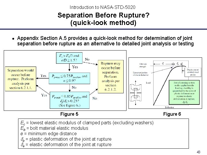
Introduction to NASA-STD-5020 Separation Before Rupture? (quick-look method) Appendix Section A. 5 provides a quick-look method for determination of joint separation before rupture as an alternative to detailed joint analysis or testing Figure 5 Figure 6 Ec = lowest elastic modulus of clamped parts (excluding washers) Eb = bolt material elastic modulus e = minimum edge distance dp = plastic deformation of the joint at rupture de = elastic deformation of the joint at rupture 43
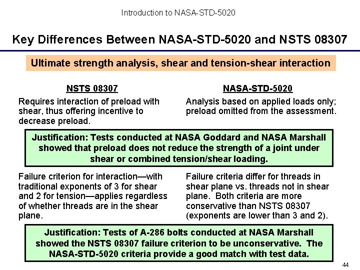
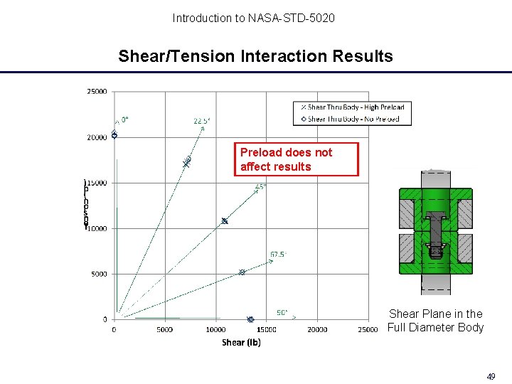
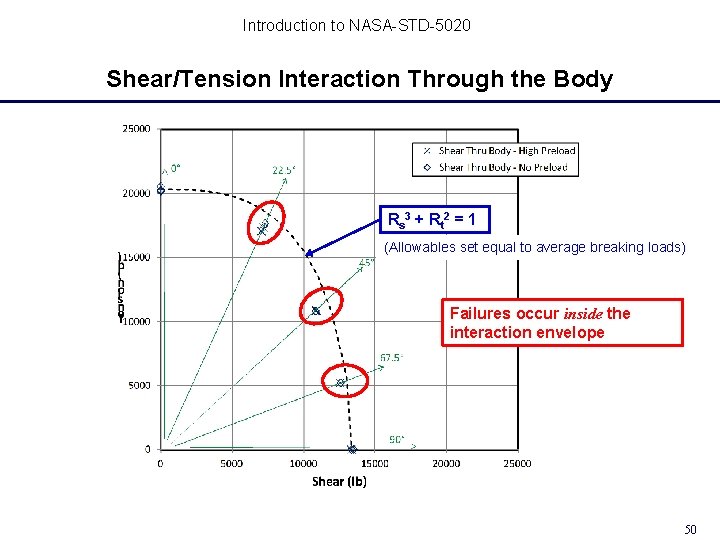
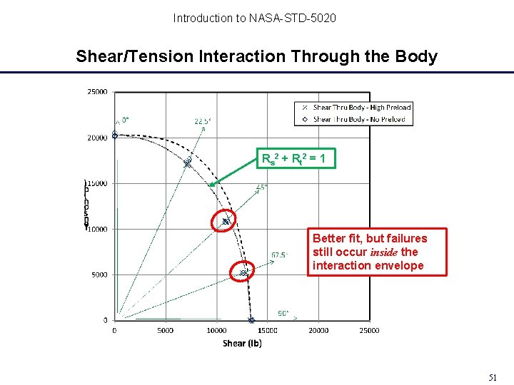
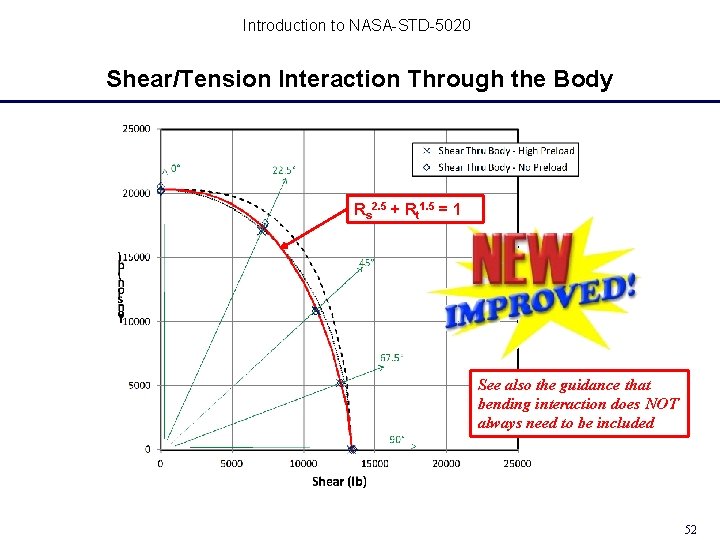
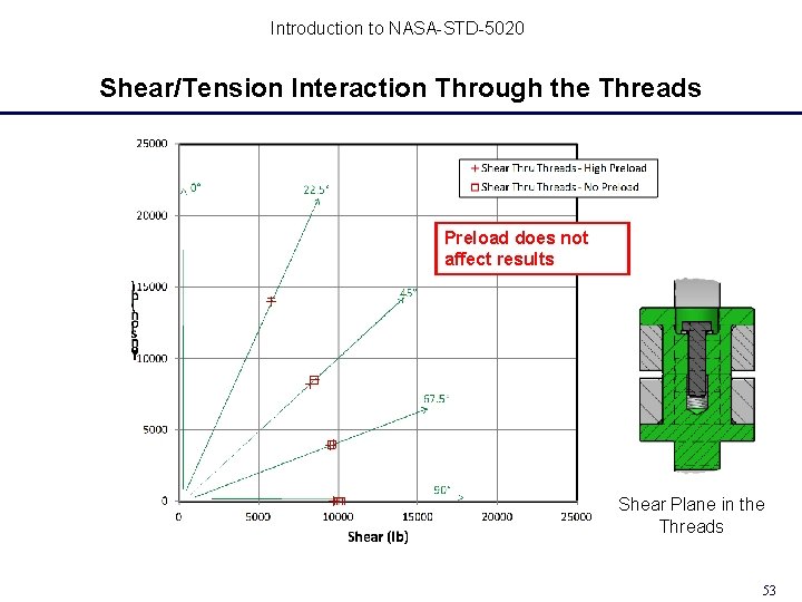
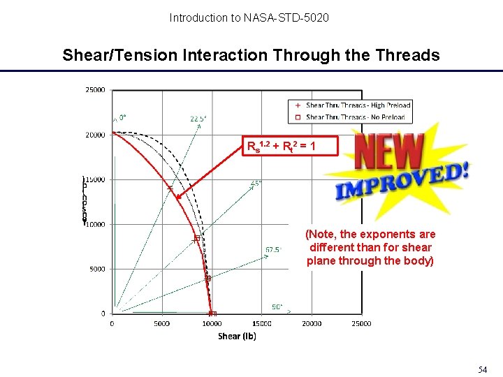
Introduction to NASA-STD-5020 Key Differences Between NASA-STD-5020 and NSTS 08307 Ultimate strength analysis, shear and tension-shear interaction NSTS 08307 Requires interaction of preload with shear, thus offering incentive to decrease preload. NASA-STD-5020 Analysis based on applied loads only; preload omitted from the assessment. Justification: Tests conducted at NASA Goddard and NASA Marshall showed that preload does not reduce the strength of a joint under shear or combined tension/shear loading. Failure criterion for interaction—with traditional exponents of 3 for shear and 2 for tension—applies regardless of whether threads are in the shear plane. Failure criteria differ for threads in shear plane vs. threads not in shear plane. Both criteria are more conservative than NSTS 08307 (exponents are lower than 3 and 2). Justification: Tests of A-286 bolts conducted at NASA Marshall showed the NSTS 08307 failure criterion to be unconservative. The NASA-STD-5020 criteria provide a good match with test data. 44
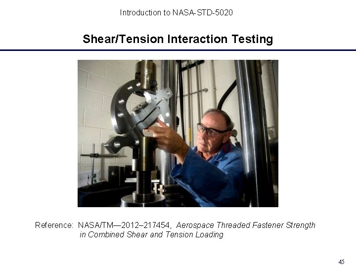
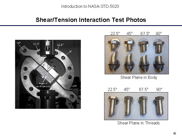
Introduction to NASA-STD-5020 Shear/Tension Interaction Testing Reference: NASA/TM— 2012– 217454, Aerospace Threaded Fastener Strength in Combined Shear and Tension Loading 45
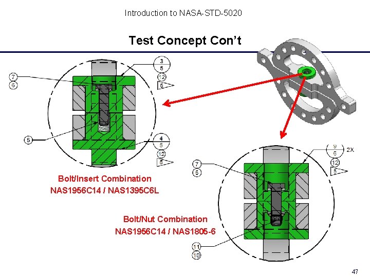
Introduction to NASA-STD-5020 Shear-Tension Interaction Test Concept A re-usable, variable position test fixture installed into a load frame to create combined tension and shear loadings Load Bolt tension-only load orientation 46 bolts tested Variables: Shear-tension load ratio (via fixture orientation) Location of shear plane (thru body or threads) Preload (with and without) Test Bolt Fixture concept: Brian Steeve (MSFC) Load 46
Introduction to NASA-STD-5020 Test Concept Con’t Bolt/Insert Combination NAS 1956 C 14 / NAS 1395 C 6 L Bolt/Nut Combination NAS 1956 C 14 / NAS 1805 -6 47
Introduction to NASA-STD-5020 Shear/Tension Interaction Test Photos 22. 5° 45° 67. 5° 90° Shear Plane in Body 22. 5° 45° 67. 5° 90° Shear Plane in Threads 48
Introduction to NASA-STD-5020 Shear/Tension Interaction Results Preload does not affect results Shear Plane in the Full Diameter Body 49
Introduction to NASA-STD-5020 Shear/Tension Interaction Through the Body Rs 3 + Rt 2 = 1 (Allowables set equal to average breaking loads) Failures occur inside the interaction envelope 50
Introduction to NASA-STD-5020 Shear/Tension Interaction Through the Body Rs 2 + Rt 2 = 1 Better fit, but failures still occur inside the interaction envelope 51
Introduction to NASA-STD-5020 Shear/Tension Interaction Through the Body Rs 2. 5 + Rt 1. 5 = 1 See also the guidance that bending interaction does NOT always need to be included 52
Introduction to NASA-STD-5020 Shear/Tension Interaction Through the Threads Preload does not affect results Shear Plane in the Threads 53
Introduction to NASA-STD-5020 Shear/Tension Interaction Through the Threads Rs 1. 2 + Rt 2 = 1 (Note, the exponents are different than for shear plane through the body) 54
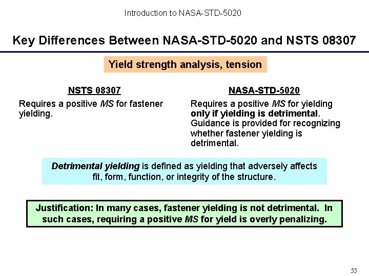
Introduction to NASA-STD-5020 Key Differences Between NASA-STD-5020 and NSTS 08307 Yield strength analysis, tension NSTS 08307 Requires a positive MS for fastener yielding. NASA-STD-5020 Requires a positive MS for yielding only if yielding is detrimental. Guidance is provided for recognizing whether fastener yielding is detrimental. Detrimental yielding is defined as yielding that adversely affects fit, form, function, or integrity of the structure. Justification: In many cases, fastener yielding is not detrimental. In such cases, requiring a positive MS for yield is overly penalizing. 55
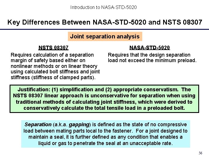
Introduction to NASA-STD-5020 Key Differences Between NASA-STD-5020 and NSTS 08307 Joint separation analysis NSTS 08307 Requires calculation of a separation margin of safety based either on nonlinear methods or on linear theory using calculated bolt stiffness and joint stiffness (stiffness of clamped parts). NASA-STD-5020 Requires that the design separation load not exceed the minimum preload. Justification: (1) simplification and (2) appropriate conservatism. The NSTS 08307 linear approach is unconservative for separation when using traditional methods of calculating joint stiffness, which were derived to conservatively calculate the total tensile load in a preloaded bolt. Separation (a. k. a. gapping) is defined as the state of no compressive load between mating parts local to the fastener. For a joint designed to maintain a seal, it is further defined as any condition that enables a liquid or gas to penetrate the seal at an unacceptable rate. 56
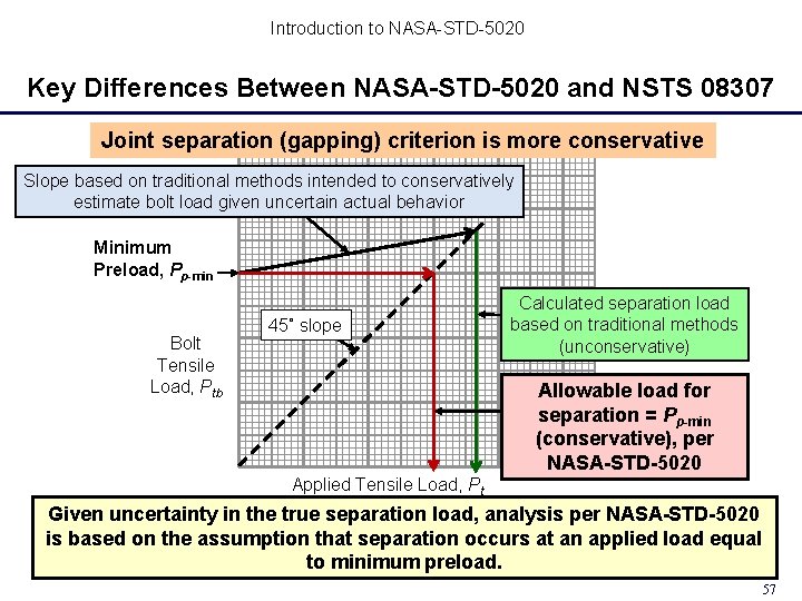
Introduction to NASA-STD-5020 Key Differences Between NASA-STD-5020 and NSTS 08307 Joint separation (gapping) criterion is more conservative Slope based on traditional methods intended to conservatively estimate bolt load given uncertain actual behavior Minimum Preload, Pp-min Bolt Tensile Load, Ptb 45˚ slope Calculated separation load based on traditional methods (unconservative) Allowable load for separation = Pp-min (conservative), per NASA-STD-5020 Applied Tensile Load, Pt Given uncertainty in the true separation load, analysis per NASA-STD-5020 is based on the assumption that separation occurs at an applied load equal to minimum preload. 57
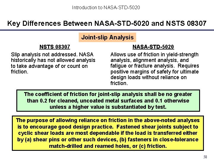
Introduction to NASA-STD-5020 Key Differences Between NASA-STD-5020 and NSTS 08307 Joint-slip Analysis NSTS 08307 Slip analysis not addressed. NASA historically has not allowed analysis to take advantage of or count on friction. NASA-STD-5020 Allows use of friction in yield-strength analysis, alignment analysis, and fatigue or fracture analysis. Requires positive margins of safety for ultimate design loads without reliance on friction. The coefficient of friction for joint-slip analysis shall be no greater than 0. 2 for cleaned, uncoated metal surfaces and 0. 1 otherwise unless a higher value is substantiated by test. The purpose of allowing reliance on friction in the above-noted analyses is to encourage good design practice. Fastened shear joints subject to cyclic shear loads are most dependable if the load is transferred either by (a) shear pins or other such devices, (b) fasteners in close-tolerance match-drilled and reamed holes, or (c) friction. 58
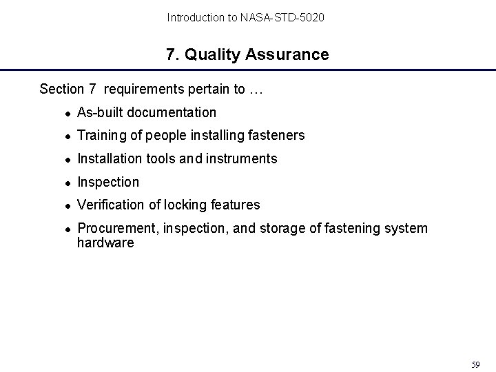
Introduction to NASA-STD-5020 7. Quality Assurance Section 7 requirements pertain to … As-built documentation Training of people installing fasteners Installation tools and instruments Inspection Verification of locking features Procurement, inspection, and storage of fastening system hardware 59
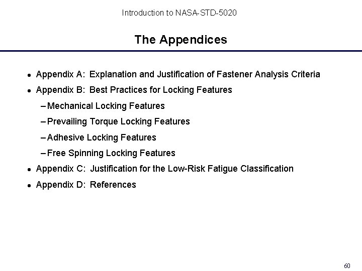
Introduction to NASA-STD-5020 The Appendices Appendix A: Explanation and Justification of Fastener Analysis Criteria Appendix B: Best Practices for Locking Features – Mechanical Locking Features – Prevailing Torque Locking Features – Adhesive Locking Features – Free Spinning Locking Features Appendix C: Justification for the Low-Risk Fatigue Classification Appendix D: References 60
Introduction to NASA-STD-5020 Summary If embraced by spaceflight-hardware developers, NASA-STD-5020 should help programs avoid costly problems and mission failures associated with threaded fasteners. Please contact the NESC Mechanical Systems Team of any errors or omissions in NASA-STD-5020. 61
Metal Fatigue Part 1 May 22 nd, 1 PM ET Mr. Raymond Patin Learning from the Past, Looking to the Future Page: 62