JK Flipflop Counters 1 The JK flipflop takes


- Slides: 6

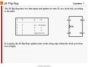
JK Flip-flop Counters 1 The JK flip-flop takes two data inputs and updates its state Q, on a clock tick, according to the table: J K Q ~Q -----------0 0 no change 0 1 0 1 1 opposite J Q CK K ~Q In Logisim, the JK flip-flops updates state on the rising edge (when the clock goes from low to high). Computer Organization I

A mod-16 Counters 2 We can use JK flip-flops to implement a 4 -bit counter: Note that the J and K inputs are all set to the fixed value 1, so the flip-flops "toggle". As the clock signal runs, the circuit will cycle its outputs through the values 0000, 0001, 0010, . . . , 1111 and then repeat the pattern. So, it counts clock ticks, modulo 16. Computer Organization I

mod-16 Counter: first tick Counters 3 Suppose the counter is in the initial state shown below (output is 0000). When the clock cycles from high to low: - the left-most sees its (inverted) clock signal go from low to high, and so it toggles its state to 1 - the next flip-flop sees its clock signal go from high to low, and so it doesn't toggle - and so, neither do the other flip-flops… So, the output is 0001. Computer Organization I

mod-16 Counter: second tick Counters 4 Suppose the counter is now in the state shown below (output is 0001). When the clock cycles from high to low (2 nd cycle): - the left-most sees its (inverted) clock signal go from low to high, and so it toggles its state to 0 - the next flip-flop sees its clock signal go from low to high, and so it toggles its state to 1 - the next flip-flop sees its clock signal go from high to low, so it doesn't toggle So the output is 0010. Computer Organization I

mod-16 Counter: third tick Counters 5 Suppose the counter is now in the state shown below (output is 0010). When the clock cycles from high to low (3 rd cycle): - the left-most sees its (inverted) clock signal go from low to high, and so it toggles its state to 0 - the next flip-flop sees its clock signal go from high to low, and so it doesn't toggle So the output is 0011. Computer Organization I

A mod-8 Parallel Counters 6 We can use JK flip-flops to implement a 3 -bit parallel counter: As the clock signal runs, the circuit will cycle its outputs through the values 000, 001, 010, . . . , 111 and then repeat the pattern. So, it counts clock ticks, modulo 8. Computer Organization I


