Jacob Adams LIGHT AND FAST TERRESTRIAL GAMMA FLASH

Jacob Adams LIGHT AND FAST TERRESTRIAL GAMMA FLASH RECORDER
 is a ~millisecond burst of radiation � Produced from")
A Terrestrial Gamma-ray Flash (TGF) is a ~millisecond burst of radiation � Produced from lightning strikes � Beamed from within thunderstorm, 1015 km up in the atmosphere � Accelerated electrons with energies up to tens of Me. V (this is disputed) � Short duration on the order of 0. 1 to 2 ms � Extraordinarily bright ~1018 gamma rays

TGF’s can be harmful � High energy electrons scattered by TGF’s can escape the atmosphere and hit orbiting spacecraft (Dwyer et al. , 2008; Briggs et al. , 2011) � Radiation is intense enough to create health concern for passengers and crew (Dwyer et al. , 2010)

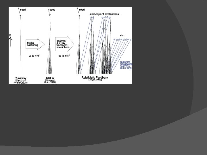
TGF’s are created by high energy electrons Electrons are accelerated via strong electric field inside a thundercloud. These high energy electrons collide with the air and emit gamma rays through bremsstrahlung interactions. (Kippen, 2012) � Still unsure what causes the initial avalanche of electrons � Bremsstrahlung interaction

Previous detection of TGF’s � BATSE 1994 � First detection � Found association with thunderstorms � RHESSI 2005 � Measured many TGF’s, � Energies greater than 20 Me. V � Association with Intra Cloud (IC) lightning � Adele 2009 -present � Flown on a plane at ~14 km � ADELE passed by 1213 lightning flashes within 10 km horizontal distance and saw only one TGF (Smith, 2011)
 aims to answer questions about TGF’s What is")
Light and Fast TGF Recorder (LAFTR) aims to answer questions about TGF’s What is the low intensity end of the luminosity distribution? � What production model is favored by the time substructure? � TGF map from RHESSI satellite data TGF time profiles from BATSE satellite data (Fishman et al. 1994, Science)

LAFTR has advantages over previous detectors � Get closer to the thunderstorm � Gain signal according to 1/r 2 � Some atmospheric absorption is eliminated as compared to satellites Lightweight, micro payload design allows for wide deployment � High time resolution �

Mechanical design requirements � Withstand forces of up to 2 g’s on takeoff and 10 g’s on parachute deployment � Shield electronic components from noise � Total weight less than 6 lb � Keep payload thermally stable

Design � Surround individual components in aluminum enclosures to avoid noise � Bolt aluminum enclosures together and place into thin plastic shell � Plastic shell placed into polythene foam box for insulation and shock absorption � Wrapped in aluminum tape to reflect radiation from the sun

Transparent portion is the plastic case, red case represents the power supply, yellow case is the UCSC board, orange case is the MSU board, and the black case is the detector (PMT). Units given in inches Transparent portion is the foam enclosure, colored box is the plastic case. Units given in inches.

In the meantime � Get PMT detector up and running for testing � Use oscilloscope to generate a function similar to that of an event in order to test the software
. 2. D.")
References 1. D. M. Smith et al. , Science 307, 1085 (2005). 2. D. Smith. (2015). Results and Prospects for Terrestrial Gamma-ray Flashes [Power. Point slides]. 3. M. Kippen. (2012). Terrestrial Gamma-ray Flashes [Power. Point slides]. Retrieved from http: //permalink. lanl. gov/object/tr? what=info: lanl-repo/lareport/LA -UR-12 -26453 4. D. M. Smith, J. R. Dwyer, B. J. Hazelton, B. W. Grefenstette, G. F. M. Martinez-Mc. Kinney, Z. Y. Zhang, A. W. Lowell, N. A. Kelley, M. E. Splitt, S. M. Lazarus, W. Ulrich, M. Schaal, Z. H. Saleh, E. Cramer, H. K. Rassoul, S. A. Cummer, G. Lu, R. J. Blakeslee, Geophys. Res. Lett. 38(8), L 08807 (2011 b)
- Slides: 13