Isothermal Transformation Diagrams TimeTemperatureTransformation TTT Diagrams Plot temperature


- Slides: 16

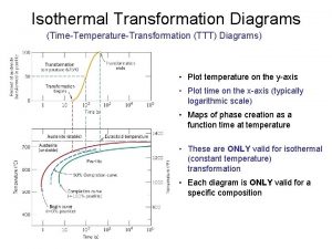
Isothermal Transformation Diagrams (Time-Temperature-Transformation (TTT) Diagrams) • Plot temperature on the y-axis • Plot time on the x-axis (typically logarithmic scale) • Maps of phase creation as a function time at temperature • These are ONLY valid for isothermal (constant temperature) transformation • Each diagram is ONLY valid for a specific composition

Consider Eutectoid Transformation … Þ + Fe 3 C Eutectoid transformation (Fe-C): 0. 76 wt% C 6. 7 wt% C 0. 022 wt% C 1600 d L 1400 1200 +Fe 3 C Eutectoid: Equil. Cooling: Ttransf. = 727ºC 800 DT 600 727°C +Fe 3 C Undercooling by DTtransf. < 727 C 400 0 (Fe) 0. 76 ferrite L+Fe 3 C 1148°C 1000 0. 022 +L (austenite) Fe 3 C (cementite) T(°C) 1 2 3 4 5 6 6. 7 Co , wt%C

Isothermal Transformation Diagrams y, % transformed • Fe-C system, Co = 0. 76 wt% C • Transformation at T = 675°C. 100 T = 675°C 50 0 10 2 1 T(°C) Austenite (stable) 10 4 time (s) TE (727 C) 600 Pearlite isothermal transformation at 675°C 500 400 % 100 te 50%pearli 0% 700 Austenite (unstable) 1 10 10 2 10 3 10 4 10 5 time (s)

Effect of Cooling History in Fe-C System • Eutectoid composition, Co = 0. 76 wt% C • Begin at T > 727°C • Rapidly cool to 625°C and hold isothermally. T(°C) Austenite (stable) 700 600 TE (727 C) Austenite (unstable) % 100 pea 50% 500 Pearlite 400 1 10 10 2 10 3 time (s) 10 4 10 5

Hypoeutectoid TTT Diagram T(°C) d L +L L+Fe 3 C 1148°C 0 1 (Fe) Fe 3 C +Fe 3 C 727°C +Fe 3 C 2 3 4 5 6 6. 7 Co , wt%C • Af represents highest temperature ferrite can form • As is the eutectoid temperature • MS is the martensite start temperature Isothermal transformation diagram for 0. 35% C, 0. 37% Mn Reed-Hill, Abbaschian, Physical Metallurgy Principles, 3 rd Edition, PWS Publishing Company, 1994.

Hypereutectoid TTT Diagram T(°C) d L +L L+Fe 3 C 1148°C 0 1 (Fe) Fe 3 C +Fe 3 C 727°C +Fe 3 C 2 3 4 5 6 6. 7 Co , wt%C • Af represents highest temperature ferrite can form • As is the eutectoid temperature • MS is the martensite start temperature Isothermal transformation diagram for 1. 13%C, 0. 30% Mn Reed-Hill, Abbaschian, Physical Metallurgy Principles, 3 rd Edition, PWS Publishing Company, 1994.

Metastable Phase Transformations • Where on this diagram is martensite shown? • How about bainite? • How about spheroidite? This is the EQUILIBRIUM Phase Diagram for Fe-C system Metastable phases are temporary phase which are intermediate between the initial and equilibrium states

Spheroidite T(°C) d L +L (ferrite) L+Fe 3 C 1148°C Fe 3 C (cementite) 727°C +Fe 3 C 0 1 (Fe) 2 3 4 5 Fe 3 C +Fe 3 C 6 6. 7 Co , wt%C 60 m • Equilibrium phase diagram tells us that the stable phase distribution in the two phase field is: + Fe 3 C – typically as lamellar microstructural constituent pearlite • Is pearlite the lowest energy state – NO! With lamellar structure pearlite has a lot of interfacial energy • If we anneal a pearlite microstructure we will get a transformation to a new phase distribution that minimizes the energy of the system when atomic mobility is activated Spheroidite: -- grains with spherical Fe 3 C

Martensite Transformation • Formed by rapid quenching of an alloy • Occurs in several alloy systems (indium-thallium, titanium, nickel-iron, gold-cadmium, and Steel) • Shear driven atomic realignment – similar to deformation twinning only more complex • Militaristic transformation – diffusionless transformation • Only driven by changes in temperature -- DG • New lattice is formed around a habit plane (plane shared between parent and daughter phases) • Form lens-shaped shear plates during transformation – speed of transformation can approach speed of sound in the material • Congruent phase change

Martensitic Transformation Bain distortion: conversion of one lattice into another by expansion or contraction along crystallographic axes Lattice parameters change as we increase the amount of carbon in solution Reed-Hill, Abbaschian, Physical Metallurgy Principles, 3 rd Edition, PWS Publishing Company, 1994.

Martensite Effects • Change in volume associated with formation of martensite • For a 1% carbon steel we see a volume increase of 4% • The shear transformation and the volume change combine to create a high density of dislocations • Lath martensite has internal dislocation density on the order of 1015 – 1016 /m 2 • Very fine microstruture of cell boundaries and laths

Mechanical Properties Source: H. K. D. H. Bhadeshia, Bainite in Steels, 2 nd Edition, Cambridge Press, 2001.

Bainite • Bainite: -- lathes (strips) with long rods of Fe 3 C --diffusion controlled. • Isothermal Transf. Diagram 800 Austenite (stable) T(°C) A 100% pearlite/bainite boundary 100% bainite 400 B A 10 103 % 100 10 -1 50% 0% 200 a (ferrite) TE P 600 Fe 3 C (cementite) 105 time (s) 5 m

Tempering Martensite • reduces brittleness of martensite, • reduces internal stress caused by quenching. TS(MPa) YS(MPa) 1800 1400 TS YS 1200 1000 60 50 %RA 40 30 %RA 800 200 400 9 m 1600 Adapted from Fig. 10. 33, Callister 7 e. (Fig. 10. 33 copyright by United States Steel Corporation, 1971. ) 600 Tempering T (°C) • produces extremely small Fe 3 C particles surrounded by . • decreases TS, YS but increases %RA

Alloying Additions Effect of adding other elements Change transition temp. Cr, Ni, Mo, Si, Mn retard + Fe 3 C transformation 4340 steel (alloyed steel)

Cooling Curve plot temp vs. time
 Isothermal transformation definition
 Ttt-järjestelmä
 Diagram annealing
 Slidetodoc.com
 If you teach me i will learn
 Esferoidita diagrama ttt
 Diagrama ttt
 Non isothermal reactor design problems
 Isothermal process
 First law of thermodynamics
 Thomson
 Isobaric isothermal ensemble
 Isothermal
 Adiabatic irreversible
 Itc calorimetry principle
 Isothermal reactor design
 Thermodynamic property relations
